CSI-200E
广东电网公司惠州惠阳供电局——自动化QC小组(第八名)
否
网络连接线全部具备屏蔽层,且屏蔽层两端接地良好。
未装设防 现场 遭受雷击的 8 个 110kV 变电站由于设计年份较早,建造时
8 止感应雷
调查 并未考虑二次防雷,而表 4-2 中的 24 起雷击故障均发生在
是
电的泄流
该 8 个变电站。经现场确认,站内自动化系统并无装设任何
8
装置
课题名称
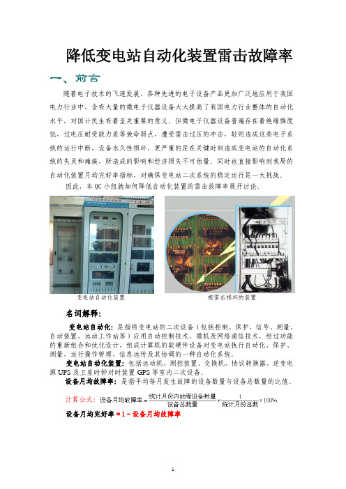
降低变电站自动化装置雷击故障率
小组类型 活动日期 小组成员
攻关型
组长
2008 年 2 月至 2009 年 2月
课题注册时间
5人
小组注册编号
罗步升 2008-02-01 H 2008-111
序号 1 2 3 4 5
6
获奖情况:获 2001 年度全国优秀质量管理小组
姓名 性别 文化程度
职务/职称
省公司有防雷相关规定如下:《广电生〔2007〕5 号广东电
站 防 雷 相 查找有 网公司变电站二次系统防雷接地规范》;2005 年 5 月的《广
2
关规定与 要求
关规定
东电网 110~220kV 变电站自动化系统技术规范》中的 14.1 中的要求如下:变电站自动化系统应设有防雷和防止过电压
的保护措施。
《惠阳供电局自动化系统运行管理规定》中考核要求如下:
没有防雷
相关考核
3
制度
现场 调查
变电站自动化装置的月均完好率应≥99.2%。而从选题理由 及现状调查环节的数据中,我们发现,雷击故障率高是影响 自动化装置月均完好率的主要因素,因而《惠阳供电局自动 化系统运行管理规定》实际也考核到自动化装置的雷击故障
小组 分工
刘琼章 男
研究生
副局长
全面指导
MPI TS200-SE 200 mm手动探头系统说明书

Universal Use• Designed for wide variety of applications such as Device Characterization, High Power and Modeling, RF and mmW Wafer Level Reliability, and Failure Analysis MPI ShielDEnvironment™ for Accurate Measurements • Design for Advanced EMI / RFI / Light-Tight Shielding • FemtoAmp low-leakage capabilities • Integrated vibration isolation• Ready for temperature range -60 °C to 300 °C Ergonomic Design and Options• Unique puck controlled air bearing stage for quick single-handed operation• Available with various chuck options and wide range of accessories such as DC/RF/mmWMicroPositioners, microscopes and ShielDEnvi-roment™ provide excellent support for various application requirementsMPI TS200-SE | 200 mm Manual Probe System withShielDEnvironment TM For accurate and reliable DC/CV, High Power, RF and mmW measurementsFEATURES / BENEFITSSPECIFICATIONSChuck XY Stage (Standard)Travel range 225 x 260 mm (8.9 x 10.2 in)Fine-travel range 25 x 25 mm fine micrometer control Fine-travel resolution < 1.0 µm (0.04 mils) @ 500 µm/rev Planarity< 10 µm Theta travel (standard)360°Theta travel (fine)± 5.0°Theta resolution 7.5 x 10⁻³ gradientMovement Puck controlled air bearing stageChuck Z Stage Travel range 5 mm (0.2 in)Fine-travel resolution < 1.0 µm (0.04 mils) @ 500 µm/rev Load stroke20 mm, pneumatically Manual Microscope Stage (Linear)Movement range*50 x 50 mm (2 x 2 in) Resolution < 5 µm (0.2 mils)Scope lift Manual, tilt-back or vertical (depending on microscope type)MovementIndependently controlled X and Y movement with locking screws *In case of ShielDEnvironment™ X x Y: 25 mm x 25 mmPROBE PLATENPLATEN LIFT WITH Probe Hover Control™MPI Probe Hover Control™ comes with hover heights (50, 100 or 150 µm) for easy and convenient probe to pad alignment.Separation Probe Hover Control™Probe in contactShielDEnvironment™MPI ShielDEnvironment™ is a high performance local environmental chamber providing excellent EMI- and light-tight shielded test environment for ultra-low noise, low capacitance measurements.MPI ShielDEnvironment™ allows up to 4-port RF or up to 8-ports DC/Kelvin or a combination of those configu-rations. MPI ShielDCap™ provides easy reconfiguration of measurement setup as well as EMI/noise shielding - which make great difference in simplifying day to day operations.ShielDEnvironment™ Electrical Specifications*EMI shielding > 30 dB (typical) @ 1 kHz to 1 MHz Light attenuation ≥ 130 dBSpectral noise floor ≤ -180 dBVrms/rtHz (≤ 1 MHz)System AC noise≤ 5 mVp-p (≤ 1 GHz)*Including 4 MicroPositioners.TYPICAL CONFIGURATION WITH MPI KELVIN AND MPI KELVIN-HIGH TEMPERATRUE PROBES INSIDE ShielDEnvironment TMTypical MPI configuration with Kelvin ProbesTS200-IFE WITH IceFreeEnvironment™As an alternative to the ShieDEnvironment TM, MPI IceFreeEnvironment TM provides unique capability to perform measurements with probe cards and MicroPositioners simultaneously, especially at neg ative temperatures down to -60 °C.Internal node probing with active/passive high impedance probes is very convenient.The optimized design with minimal tip drop for highest dynamic range and gamma of mmWave and Load Pull measurements make the system an ideal choice for RF/mmW applications on 200 mm wafers.HIGH POWER PROBE ACCESSORIESHigh Voltage Probe (HVP)Low leakag e probes specially desig ned to withstandhig h voltag e up to 10 kV (coaxial) and 3 kV (triaxial).Choice of various connectors options such as KeysightTriax/UHV, Keithley Triax/UHV, SHV or Banana.High Current Probe (HCP)High performance probes specially designed for on wa-fer measurement of hig h current up to 200 A (pulse).MPI multi-fingers high current probes are single piececonsturction to efficiently handle high current and pro-vide low contact resistance.Ultra High Power Probe (UHP)Desig ned for Ultra hig h voltag e and current on wafermeasurement up to 10 kV/600 A (pulse). MPI replaceablemulti-fingers probes tips and probe arms are design forlow contact resistance for ultra-high current measure-ment and to support ultra-high voltage of up to 10 KV,without having to change probes for high voltage andcurrent application.1 finger4 fingers6 fingers8 fingers12 fingersMax current*20 A 80 A 120 A 160 A 250 A Max voltage10 KV 10 KV 10 KV 10 KV 10 KV Residual resistance (Typical)≤ 5 mΩ≤ 3 mΩ≤ 1 mΩ ≤ 1 mΩ≤ 1 mΩConnector options Banana Banana Banana Banana Banana Replaceable tipYes Yes Yes Yes Yes Probe tip width 250 µm 250 µm 250 µm 250 µm 250 µm Probe pitch--650 µm650 µm650 µm650 µm*1 ms Max PW, 0.4% max PLCUL TRA HIGH POWER PROBES - SELECTION GUIDEHIGH POWER PROBE CARDSHIGH POWER PROBES - SELECTION GUIDE[2]Keysight or Keithley [3]Banana: 100 A max, 1 ms max PW, 1% max PLC [4]BNC: 40 A max, 1 ms max PW, 1% Max PLCNON-THERMAL CHUCKSStandard Wafer ChuckConnectivity Coax BNC (f)Diameter210 mmMaterial Stainless steelChuck surface Planar with centric engraved vacuum groovesVacuum grooves sections(diameter) 3, 27, 45, 69, 93, 117, 141, 164, 194 mmVacuum actuation Multizone control - All connected in meander shape, center hole in 3mm diameterSupported DUT sizes Single DUTs down to 5 x 5 mm size or wafers 50 mm (2 in) thru 200 mm(8 in)*Surface planarity≤± 5 µm**Rigidity< 15 µm / 10 N @edge*Single DUT testing requires higher vacuum conditions dependent upon testing application.**By using SENTIO® topographyRF Wafer Chuck (Triaxial)Connectivity Kelvin Triax (f)Diameter210 mm with 2 integrated AUX areasMaterial Nickel plated aluminum (flat with 0.5 mm holes)Chuck surface Planar with 0.5 mm diameter holes in centric sectionsVacuum holes sections (diameter)3, 27, 45, 69, 93, 117, 141, 164, 194 mmVacuum actuation Manual switch between Center (4 holes), 100, 150, 200 mm (4, 6, 8 in) Supported DUT sizes Single DUTs down to 5 x 5 mm size or wafers 100 mm (4 in) thru 200 mm (8 in)* Surface planarity≤± 5 µm**Rigidity< 15 µm / 10 N @edge*Single DUT testing requires higher vacuum conditions dependent upon testing application.**By using SENTIO® topographyHigh Power ChucksConnectivity 110 kV Coaxial (Banana or SHV)Connectivity 2Kelvin Triax (f), 3 kV or 10 kV CoaxialDiameter210 mm with 2 integrated AUX areasMaterial Gold plated aluminum (flat with 100 µm holes)Chuck surface Planar with 0.5 mm diameter holes in centric sectionsVacuum holes sections (diameter)3, 27, 45, 69, 93, 117, 141, 164, 194 mmVacuum actuation Manual switch between Center (4 holes), 100, 150, 200 mm (4, 6, 8 in) Supported DUT sizes Single DUTs down to 5 x 5 mm size or wafers 100 mm (4 in) thru 200mm (8 in)*Surface planarity≤± 5 µmRigidity< 15 µm / 10 N @edge*Single DUT testing requires higher vacuum conditions dependent upon testing application.Electrical Specification (Coax)Operation voltageIn accordance with EC 61010, certificates for higher voltages available upon request Maximum voltage between chuck top and GND 500 V DC Isolation> 2 GΩElectrical Specification (RF - Triax)Chuck isolation Standard Chuck (10 V)Force to guard ≥ 1 TΩGuard to shield ≥ 1 TΩForce to shield≥ 5 TΩAuxiliary Chuck Quantity 2 AUX chucksPositionIntegrated to front side of main chuck Substrate Size (W x L)Max. 25 x 25 mm (1 x 1 in)Material Ceramic, RF absorbing material for accurate calibration Surface planarity ≤± 5 µmVacuum controlControlled independently, separate from chucksElectrical Specification (High Power - Triax)Chuck isolation > 30 TΩForce to guard > 30 TΩGuard to shield > 500 GΩForce to shield> 100 GΩMPI Non-thermal Triaxial Hig h Power Chuck with g oldplated surface for low contact resistanceMPI 10 kV Triaxial Connector used for Kelvin chuck connectionTHERMAL CHUCKSSpecifications of MPI ERS AirCool® TechnologyAmbient to 150/200 °C 20 °C to 150/200 °C-40 °C to 150/200 °C Connectivity Coax BNC (f)Coax BNC (f)Coax BNC (f)Temperature control methodCooling air /Resistance heaterCooling air /Resistance heaterCooling air /Resistance heaterCoolant Air (user supplied)Air (user supplied)Air (user supplied) Smallest temperatureselection step0.1 °C0.1 °C0.1 °C Chuck temperaturedisplay resolution 0.1 °C0.1 °C0.1 °C External touchscreendisplay operation N/A N/A N/A Temperature stability ±0.5 °C±0.5 °C±0.5 °C Temperature accuracy ±1 °C±1 °C±1 °C Control method DC/PID DC/PID DC/PID Chuck pinhole surfaceplating: 200 °C Nickel Nickel Nickel Vacuum distribution In center for 5x5 mm (4 holes) 100, 150, 200 mm (4, 6, 8 in) Temperature sensor Pt100 1/3DIN Pt100 1/3DIN Pt100 1/3DIN Temperature uniformity< ±1 °C< ±1 °C< ±1 °C Surface flatness andbase parallelism < ±15 µm < ±15 µm < ±15 µm Max. Voltage betweenForce-to-GND500 V DC500 V DC500 V DCHeating rates*35 to 150 °C < 12 min35 to 200 °C < 18 min 20 to 150 °C < 12 min20 to 200 °C < 23 min-40 to 25 °C < 12 min25 to 200 °C < 16 minCooling rates*150 to 35 °C < 15 min200 to 35 °C < 18 min 150 to 20 °C < 18 min200 to 20 °C < 30 min200 to 25 °C < 20 min25 to -40 °C < 36 minLeakage @ 10 V N/A N/A N/A Electrical isolation > 0.5 T Ω at 25 °C> 0.5 T Ω at 25 °C> 0.5 T Ω at 25 °C Capacitance< 750 pF< 750 pF< 750 pF*Typical data for all chucks based on FPS requirements.Specifications of MPI ERS AirCool® PRIME TechnologyAmbient to 200/300 °C20 °C to200/300 °CAmbient to200/300 °C20 °C to200/300 °CChuck type RF RF Ultra low noise Ultra low noise Connectivity Kelvin Triax (f)Kelvin Triax (f)Kelvin Triax (f)Kelvin Triax (f)Temperature control methodCooling air /Resistance heaterCooling air /Resistance heaterCooling air /Resistance heaterCooling air /Resistance heaterCoolant Air (user supplied)Air (user supplied)Air (user supplied)Air (user supplied) Smallest temperatureselection step0.1 °C0.1 °C0.1 °C0.1 °C Chuck temperaturedisplay resolution 0.01 °C0.01 °C0.01 °C0.01 °C External touchscreendisplay operation Yes Yes Yes Yes Temperature stability ±0.08 °C±0.08 °C±0.08 °C±0.08 °C Temperature accuracy ±0.1 °C0.1 °C0.1 °C0.1 °C Control method Low noise DC/PID Low noise DC/PID Low noise DC/PID Low noise DC/PID Chuck pinhole surfaceplating: 200°C / 300°C Nickel / Gold Nickel / Gold Nickel / Gold Nickel / GoldSmartVacuum™ distribution In front for single DUT 5x5 mm (4 holes) and 75 mm (3 in) In center for 150, 200 mm (6, 8 in)Temperature sensor Pt100 1/3DIN,4-line wired Pt100 1/3DIN,4-line wiredPt100 1/3DIN,4-line wiredPt100 1/3DIN,4-line wiredTemperature uniformity< ±0.5 °C at ≤ 200 °C< ±1 °C at > 200 °C < ±0.5 °C at ≤ 200 °C< ±1 °C at > 200 °C< ±0.5 °C at ≤ 200 °C< ±1 °C at > 200 °C< ±0.5 °C at ≤ 200 °C< ±1 °C at > 200 °CSurface flatness andbase parallelism < ±12 µm < ±12 µm < ±12 µm < ±12 µm Max. Voltage betweenForce-to-GND600 V DC600 V DC600 V DC600 V DC Force-to-Guard100 V DC100 V DC 600 V DC 600 V DC Guard-to-GND400 V DC400 V DC400 V DC400 V DCHeating rates*35 to 200 °C < 16 min35 to 300 °C < 20 min 20 to 200 °C < 15 min20 to 300 °C < 22 min35 to 200 °C < 18 min35 to 300 °C < 26 min20 to 200 °C < 16 min20 to 300 °C < 28 minCooling rates*200 to 35 °C < 23 min300 to 35 °C < 31 min 200 to 20 °C < 27 min300 to 20 °C < 32 min200 to 35 °C < 24 min300 to 35 °C < 32 min200 to 20 °C < 35 min300 to 20 °C < 34 minLeakage @ 10 VN/A N/A < 15 fA at 25 °C< 30 fA at 200 °C< 50 fA at 300 °C< 15 fA at 25 °C< 30 fA at 200 °C< 50 fA at 300 °CElectrical isolation > 5 T Ω at 25 °C> 1 T Ω at 200 °C> 0.5 T Ω at 300 °C> 5 T Ω at 25 °C> 1 T Ω at 200 °C> 0.5 T Ω at 300 °CN/A N/ACapacitanceForce-to-Guard< 1600 pF< 1600 pF< 600 pF< 600 pF Guard-to-Shield< 2000 pF< 2000 pF < 2000 pF < 2000 pF *Typical data for all chucks based on FPS requirements.Specifications of MPI ERS AirCool® PRIME with Fusion Chiller Technology> 1 T Ω at 200 °C, > 0.5 T Ω at 300 °C CapacitanceForce-to-Guard< 1600 pF< 1600 pF< 1600 pF Guard-to-Shield< 2000 pF< 2000 pF < 2000 pF *Typical data for all chucks based on FPS requirements.Specifications of MPI ERS AirCool® PRIME with Fusion Chiller Technology-10 °C to 200/300 °C -40 °C to 200/300 °C -60 °C to 200/300 °C Chuck type Ultra low noise Ultra low noise Ultra low noise Connectivity Kelvin Triax (f)Kelvin Triax (f)Kelvin Triax (f)Temperature control method Cooling air /Resistance heaterCooling air /Resistance heaterCooling air /Resistance heaterCoolant Air (user supplied)Air (user supplied)Air (user supplied) Smallest temperatureselection step0.1 °C0.1 °C0.1 °C Chuck temperaturedisplay resolution 0.01 °C0.01 °C0.01 °C External touchscreendisplay operation Yes Yes Yes Temperature stability ±0.08 °C±0.08 °C±0.08 °C Temperature accuracy 0.1 °C0.1 °C0.1 °C Control method Low noise DC/PID Low noise DC/PID Low noise DC/PID Interfaces RS232C RS232C RS232C Chuck pinhole surfaceplating: 200°C / 300°C Nickel / Gold Nickel / Gold Nickel / GoldSmartVacuum™ distribution In front for single DUT 5x5 mm (4 holes) and 75 mm (3 in)In center for 150, 200 mm (6, 8 in)Temperature sensor Pt100 1/3DIN,4-line wired Pt100 1/3DIN,4-line wiredPt100 1/3DIN,4-line wiredTemperature uniformity< ±0.5 °C at ≤ 200 °C< ±1 °C at > 200 °C < ±0.5 °C at ≤ 200 °C< ±1 °C at > 200 °C< ±0.5 °C at ≤ 200 °C< ±1 °C at > 200 °CSurface flatness andbase parallelism < ±12 µm < ±12 µm < ±12 µm Max. Voltage betweenForce-to-GND600 V DC600 V DC600 V DC Force-to-Guard600 V DC600 V DC600 V DC Guard-to-GND400 V DC400 V DC400 V DC Heating rates*25 °C-10 to 25 °C < 3 min-40 to 25 °C < 4 min-60 to 25 °C < 5 min200 °C25 to 200 °C < 15 min300 °C25 to 300 °C < 26 min25 to 300 °C < 26 min25 to 300 °C < 26 min Cooling rates*AC3 Mode300 °C300 to 25 °C < 12 min300 to 25 °C < 14 min200 °C200 to 25 °C < 8 min200 to 25 °C < 10 min25 °C25 to -10 °C < 6 min25 to -40 °C < 12 min25 to -60 °C < 26 minTURBO Mode300 °C300 to 25 °C < 12 min300 to 25 °C < 12 min200 °C200 to 25 °C < 8 min200 to 25 °C < 8 min25 °C25 to -10 °C < 6 min25 to -40 °C < 10 min25 to -60 °C < 17 min300 °C< 50 fA < 50 fA < 50 fA CapacitanceForce-to-Guard< 600 pF< 600 pF< 600 pF Guard-to-Shield< 2000 pF< 2000 pF < 2000 pF*Typical data for all chucks based on FPS requirements.HIGH POWER THERMAL CHUCKSSpecifications of MPI ERS Integrated TechnologyTemperature Range 20 to 200 °C 20 to 300 °CConnectivity Kelvin Triax (f), 3 kVor 10 kV Coaxial Kelvin Triax (f), 3 kV or 10 kV CoaxialTemperature control methodCooling air /Resistance heaterCooling air /Resistance heaterCoolant Air (user supplied)Air (user supplied) Smallest temperatureselection step0.1 °C0.1 °C Chuck temperaturedisplay resolution 0.01 °C0.01 °C External touchscreendisplay operation Yes Yes Temperature stability ±0.08 °C±0.08 °C Temperature accuracy 0.1 °C0.1 °C Control method Low noise DC/PID Low noise DC/PID Interfaces RS232C RS232CChuck surface plating Gold plated withpinhole surface Gold plated with pinhole surfaceTemperature sensor Pt100 1/3DIN,4-line wired Pt100 1/3DIN, 4-line wiredTemperature uniformity< ± 0.5 °C< ±0.5 °C at ≤ 200 °C< ±1.0 °C at > 200 °CSurface flatness andbase parallelism < ±10 µm < ±10 µm at ≤ 200 °C < ±15 µm at > 200 °CHeating rates 20 to 200 °C < 31 min 20 to 300 °C < 39 min Cooling rates*200 to 20 °C < 57 min300 to 20 °C < 55 min Maximum voltage betweenchuck top and GND 10 kV DC10 kV DC* All data are relevant for chucks in ECO mode.Specifications of MPI ERS Integrated TechnologyTemperature Range-10 to 200 °C/300 °C-40 to 200 °C/300 °C -60 to 200 °C/300 °CConnectivity Kelvin Triax (f), 3 kVor 10 kV Coaxial Kelvin Triax (f), 3 kVor 10 kV CoaxialKelvin Triax (f), 3 kVor 10 kV CoaxialTemperature control methodCooling air /Resistance heaterCooling air /Resistance heaterCooling air /Resistance heaterCoolant Air (user supplied)Air (user supplied)Air (user supplied) Smallest temperatureselection step0.1 °C0.1 °C0.1 °C Chuck temperaturedisplay resolution 0.01 °C0.1 °C0.1 °C External touchscreendisplay operation Yes Yes Yes Temperature stability ±0.08 °C±0.08 °C±0.08 °C Temperature accuracy 0.1 °C0.1 °C0.1 °C Control method Low noise DC/PID Low noise DC/PID Low noise DC/PID Interfaces RS232C RS232C RS232CChuck surface plating Gold plated withpinhole surface Gold plated withpinhole surfaceGold plated withpinhole surfaceTemperature sensor Pt100 1/3DIN,4-line wired Pt100 1/3DIN,4-line wiredPt100 1/3DIN,4-line wiredTemperature uniformity< ±0.5 °C at ≤ 200 °C< ±1.0 °C at > 200 °C < ±0.5 °C at ≤ 200 °C< ±1.0 °C at > 200 °C< ±0.5 °C at ≤ 200 °C< ±1.0 °C at > 200 °CSurface flatness and base parallelism < ±10 µm at ≤ 200 °C< ±15 µm at > 200 °C< ±10 µm at ≤ 200 °C< ±15 µm at > 200 °C< ±10 µm at ≤ 200 °C< ±15 µm at > 200 °CMaximum voltage betweenchuck top and GND 10 kV DC10 kV DC10 kV DCCooling rates*AC3 Mode300 °C300 to 25 °C < 17 min300 to 25 °C < 17 min200 °C200 to 25 °C < 14 min200 to 25 °C < 15 min25 °C25 to -10 °C < 12 min25 to -40 °C < 13 min25 to -60 °C < 25 min TURBO Mode300 °C300 to 25 °C < 17 min300 to 25 °C < 16 min200 °C200 to 25 °C < 14 min200 to 25 °C < 13 min25 °C25 to -10 °C < 12 min25 to -40 °C < 13 min25 to -60 °C < 25 min Leakage @ 10 V Kelvin Triax (f)Thermal Controller Dimensions / Power and Air ConsumptionSystem type W x D x H (mm)Weight (kg)Power cons. (VA)max. Air flow* (l/min) 20 to 200 °C / 300 °C300 x 360 x 135 12700200 System Controller / Chiller Dimensions and Power / Air ConsumptionSystem type W x D x H (mm)Weight (kg)Power cons. (VA)max. Air flow*(l/min) 20 to 200 °C / 300 °C300 x 360 x 140 121000200-10 to 200 °C / 300 °C420 x 355 x 450501650250-40 to 200 °C / 300 °C420 x 500 x 1020 1402400400-60 to 200 °C / 300 °C420 x 500 x 1020 1402400400*All data are relevant for chucks in ECO mode.ERS High Power Thermal Chuck ERS AirCool® Fusion*, ControllerIntegrated Chiller -40 °C / -60 °CERS AirCool® Fusion*, ControllerIntegrated Chiller -10 °C*ERS electronic GmbH patented solution*Typical data for all chucks based on FPS requirements.TYPICAL TRANSITION TIME200 mm PRIME RF Chuck 35°C to +300°C200 mm PRIME ULN Chuck 35°C to +300°C200 mm PRIME ULN Chuck 20°C to +300°C200 mm PRIME RF Chuck -10°C to +300°C200 mm PRIME ULN Chuck -40°C to +300°C200 mm PRIME ULN Chuck -60°C to +300°C200 mm PRIME RF Chuck -60°C to +300°C200 mm PRIME High-Power Chuck -10°C to +300°CThese chucks incorporate the ERS patented AC3 cooling technology and its air manage-ment system to purge the MPI ShielDEnvironment™ directly from “already used” air – re-ducing dry air consumption up to 30 to 50% as compared to other systems on the market.Copyright belongs to ERS electronic GmbHTS2000-HP can be configured with instrument connection package. The packages consists of necessary high voltage/high current probes and cabling accessories for optimal connection to the test instruments. Keysight B1505AHigh Power chuck shorting and floating plugs Keithley 2600-PCT-XB REGULATORY COMPLIANCEINSTRUMENT CONNECTION PACKAGE• CE certified. TÜV compliance tested according to EN 61010, ISO 12100, and SEMI S2Thermal Chuck Electrical Supply Electrical SupplyElectrical primary connection 100 to 240 VAC auto switch Frequency50 Hz / 60 HzCompressed Air Supply Operating pressure 6.0 bar (0.6 MPa, 87 psi) at specified flow rateCDA dew point ≤ 0 °C for hot chuck system (ambient to 300 °C)≤ -45 °C for hot and cold chuck system (-60 °C to 300 °C)General Probe System Power 100-240 V AC 50/60 Hz for optical accessories* only Vacuum -0.5 bar (for single DUT) / -0.3 bar (for wafers)Compressed air4 ~ 7 bar*e.g. microscope illumination, CCD cameras, monitors.FACILITY REQUIREMENTSStation Platform with Bridge*Dimensions (W x D x H)670 x 785 x 815 mm (26.4 x 30.9 x 32.1 in)Weight~150 kg (330.7 lb.)PHYSICAL DIMENSIONS*Station accessories, such as different microscopes, cameras, or laser cutters, may change the total height.WARRANTY• Warranty*: 12 months• Extended service contract: contact MPI Corporation for more information*See MPI Corporation‘s Terms and Conditions of Sale for more details.MPI Global PresenceDirect contact:Asiaregion:****************************EMEAregion:******************************Americaregion:********************************MPI global presence: for your local support, please find the right contact here:/ast/support/local-support-worldwide© 2023 Copyright MPI Corporation. All rights reserved.Vibration Isolation TableWeightApprox. 210 kg ( 463 lb.)Approx. 210 kg ( 463 lb.)。
CSI200E工程内部培训资料

目录1 型号含义 (2)2零漂、刻度的调整 (2)2.1 CSI200E/EA的零漂和刻度调整 (2)2.2 CSI200EB零漂和刻度的调整 (2)3 同期 (3)3.1 同期定值 (3)3.2同期原理 (4)4调压部分 (9)5 直流温度测量 (11)6 管理软件说明 (13)7 各插件更换事项 (15)8 常见问题 (16)1 型号含义目前测控有CSI200E、CSI200EA、CSI200EB、CSI200EC四种型号:CSI200ED,在CSI200EB前提下更改的,主要是dio板增加了开入,减少开出CSI200EA和CSI200E主要是装置外观和插件尺寸不同,(CSI200EA和新平台保护外观、结构一致),两者功能相同。
CSI200EB功能和CSI200E功能也相同,只是受资源限制,主要用于220kV及以下电压等级变电站的线路间隔。
CSI200EB硬件结构同CSC200系列。
CSI200EC主要应用在电厂。
2零漂、刻度的调整2.1 CSI200E/EA的零漂和刻度调整零漂和刻度的调整有两种方法。
一种是通道调整,一种是遥测校正。
CSI200E、CSI200EA同时支持这两种方法。
CSI200E在V2.0版本之前只有遥测校正。
V2.0版本指:MASTER 、MMI、AI均是V2.0版本。
V2.0版本后同时支持通道调整和遥测校正。
CSI200EA在AI V3.02版本(含)以后增加了允许零漂、刻度调整的跳线。
交流插件的3个地址跳线的最上面的跳线调至右边为允许调整,在左边为正常运行状态,禁止调整。
出厂时均为禁止调整状态。
现场调试完毕后,一定要把跳线跳回左侧。
通道校正作用:分插件分通道的对交流和直流插件自动调整零点漂移和刻度设置。
遥测校正作用:用广播命令对装置中所有遥测插件自动调整零点漂移和刻度设置。
注意:零漂调整时:要将电流回路开路,电压回路短路。
显示操作成功后。
进入有效值/运行值/交流1板菜单,所调通道的数据显示为0。
四方CSI200E装置管理软件使用说明书

CSI-200E测控装置管理软件使用说明书CSI-200E测控装置管理软件使用说明书编制:赵云校核:肖彬审核:邓俊波版本记录目录1概述 (1)1.1适用范围 (1)1.2硬件配置、操作系统及软件安装 (1)1.3主要功能特点 (1)2绘制间隔主接线图 (3)2.1新建及保存文件 (3)2.2元件绘制 (4)2.3主接线图下传 (7)2.4保存主接线图为位图文件 (8)3可编程逻辑控制器 (8)3.1PLC的节点分类 (8)3.2操作类型分类 (9)3.3使用规则 (10)3.4可编程逻辑的编写 (10)3.5PLC下传、上传及校验 (21)3.6PLC编程技巧 (21)3.7用PLC实现遥控功能 (22)3.8用PLC实现同期功能 (23)3.9用PLC实现调压功能 (26)3.10用PLC实现间隔间五防闭锁 (27)3.11把PLC梯形图保存为位图 (29)4装置配置 (30)4.1装置设置 (30)4.2通道配置 (34)4.3其他配置 (37)4.4下传装置配置定值 (40)561850建模 (41)5.1建模配置 (41)5.2高级配置 (47)5.3导出模型 (48)6其他部分说明 (49)6.1下载程序 (49)6.2文件.CSI说明 (50)6.3串口配置及报文显示 (50)6.4界面英化 (51)1概述1.1适用范围CSI200EManage V4.13用于CSI-200E系列数字式综合测量控制装置(以下简称装置或间隔)PC端辅助管理软件,也可用于简单的串口通讯监视。
1.2硬件配置、操作系统及软件安装在装有Windows 2000/XP(或Windows的更高版本)系统都可以使用该软件。
软件只有一个文件,即软件本身,无需安装,也不需要其他控件或库的支持,直接运行便可。
由于软件配置的所有信息都是通过串口下传到装置的,所以要求计算机至少有一个RS-232-C串口或配置USB-RS232转接器。
一个半断路器接线方式下同期电压点近区优先实现的两种思想
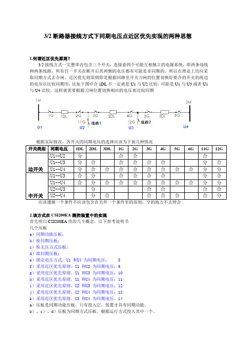
3/2断路器接线方式下同期电压点近区优先实现的两种思想1.何谓近区优先原则?3/2接线方式一完整串内包含三个开关,连接着四个可能互相独立的电源系统,即两条母线和两条线路,所有任一开关在断开后其两侧的电压都有可能是非同期的,所以在理论上均应采取同期方式去合闸。
近区优先则原则即是根据回路里开关刀闸的位置切换好要合的开关的两边的电压以比较同期用,比如下图中合1DL不一定就是U1与U2比较,可能是U1与U3或者U1与U4比较,这样就需要根据刀闸位置切换相应的电压来比较同期开关类别同期电压1DL 2DL 3DL 1G 2G 3G 4G 5G 6G 11G 12G边开关U1--U2 分合合合U1--U3 分合合合合合分合U1--U4 分合合合合合合合合分分中开关U1--U3 合分合合合合分合U1--U4 合分合合合合合合合分分U2--U3 分合合合合U2--U4 分合合合合合分应该遵循一个条件不应该包含在另外一个条件里的原则,空的地方不去理会2.该方式在CSI200EA测控装置中的实现首先明白CSI200EA里的几个概念,以下参考说明书几个压板a)同期功能压板;b)检同期压板;c)检无压方式压板;d)准同期压板;e)固定电压方式。
U1 和U4 为同期电压; 8f)采用近区优先原则。
U1 和U2 为同期电压;9g)采用近区优先原则。
U1 和U3 为同期电压;10h)采用近区优先原则。
U1 和U4 为同期电压;11i)采用近区优先原则。
U2 和U3 为同期电压;12j)采用近区优先原则。
U2 和U4 为同期电压;13k)采用近区优先原则。
U3 和U4 为同期电压。
14a)压板是同期功能压板,只有投入它,装置才具有同期功能。
b)、c)、d)压板为同期方式压板,根据运行方式投入其中一个。
e)到k)压板为同期节点方式压板,当抽取电压只有一路,投入固定方式压板;否则,根据近区优先的原则投入相应压板。
固定电压方式压板在开关经同期合闸后,压板状态不退出。
ECMS发电厂监控管理系统CSPA系统介绍(售前)

DCS系统的开放性 接口方式及性能要求 通信的可靠性(网络通信机制) 分散安装的终端设备的可靠性(电磁干扰)
2018/11/23
CSPA2000发电厂电气自动化系统
FECS系统关键技术指标
可靠性
就地安装的综保装置………………抗干扰能力 网络结构的可靠性…………………冗余配置要求
稳定性
大量的终端设备和信息量…………后台管理能力 多种终端设备及通信协议…………通信管理 DCS系统网络通信能力……………信息控制 DCS系统实时控制要求……………控制、采样速率 ……………故障切换时间
CSPA2000发电厂电气自动化系统
实时性
2018/11/23
四方公司FECS系统(CSPA200)的技术基础
6
10 8 10 2 1 1
7
80(自检、保护信息、 保护状态) 14 30 59 8 23
CSPA2000发电厂电气自动化系统
装置控制逻辑可编程
CSC200系列保护测控装置(分布式I/O) 技术特点:
2018/11/23
CSPA2000发电厂电气自动化系统
装置特点
专业嵌入式硬件结构设计,全封闭金属外壳,独特的抗干扰设计和先 进的表面贴安装工艺使系统具有很高的可靠性。
采用多CPU并行处理模式,以高性能Freescale通讯微处理器做为主CPU, 以高效率的Renesas微控制器、Neuron通讯处理芯片作为辅助处理器,同 步处理多总线接口的通信数据,配有大容量的程序存储器、数据存储器, 处理速度快、运算能力强。 采用32位MCU,低功耗,免风扇。以高性能的新型RISC(精简指令集)微 处理器为处理核心,处理速度快、运算能力强。
CSC-2000(V2)运行手册(北京四方)
CSC-2000(V2)变电站自动化监控系统运行手册符合《南方电网变电站计算机监控系统技术规范》第一章概述一.1设备标准化配置CSC-2000(V2)系统的站控层设备通常分为两类,一类是以数据通信处理功能为主,主要指远动主站,一类是以提供人机交互为主,包括监控主站、继电保护工程师站、五防工作站(可选)、A VQC主站(可选)等。
在CSC-2000系统中这些站控层的设备基本都是独立设计,其数据库也是相互独立的,但不同功能的主站有些可以同机运行;而CSC-2000(V2)系统在站控层的两类主站(数据通信处理主站和人机交互主站)之间仍采用平等独立的方式,而将系统的各种人机交互类主站(监控主站、继电保护工程师主站、维护工程师站、VQC主站、五防工作站等)统一到一个平台,共享数据,但在物理上也可以配置为单独的硬件设备,这样的配置原则既满足了数据通信处理类主站对数据处理速度的要求,又使所有人机交互主站保持数据的一致性及人机交互接口的统一风格。
因此在CSC-2000系统中我们推荐各个功能主站物理单独配置主机,而CSC-2000(V2)系统中由于各个功能主站采用的是同一的数据平台,不同的主站完全可以配置在同一台主机中。
➢监控主站监控主站主要是为变电站内运行人员提供人机交互的界面,它负责收集、处理、显示和记录间隔层设备采集的信息,并根据操作人员的命令向间隔层设备下发控制命令,从而完成对变电站内所有设备的监视和控制,有时监控主站也叫作人机接口HMI,所实现的功能主要包括:●与装置通信,获得实时及历史信息;●多种形式的实时信息显示:单线图、图形、图表等;●操作控制功能:通过屏幕/鼠标/键盘,可操作控制开关、刀闸、压板等可控对象;●灵活多样的报警处理:通过弹出窗口、图形闪烁、声音等形式及时向操作员发出事故和预告警报,提醒及时处理;●各种重要数据的保存、查询和分析;●用户的权限管理:系统管理员、维护人员、操作人员等被赋予不同权限,只有被授权人员才能进行被授权的操作,其操作行为将被记录在事件记录内;●各种记录和报表的生成与打印。
计算机监控及保护系统

大唐山西新能源公司岢岚大阳坡风电工程设备(材料)验收领用单编号: 日期:年月日设备(材料)名称计算机监控及保护系统型号规格见附件设备(材料)厂家北京四方继保自动化股份有限公司合同编号SC10002695交货日期 2018年9月25日验收日期2018年9月25日价格主要技术参数见附件验收情况:验收领用记录供货厂家:确认签字:年月日施工单位:施工单位(章)验收人:年月日项目部经理:年月日监理单位:监理单位(章)验收人:年月日项目部:项目部章设备验收人:年月日项目部经理:年月日备注设备(材料)验收领用单一式四份附件:北京四方继保自动化股份有限公司2018年9月25日到货验收清单清单列表序号物料编码名称及型号数量实发备注1 5700000054 GCSI200EA-L221型-220kv线路测控柜-现场(08)1 12 5700000054 GXH103A-G-121型-220kv线路保护柜-现场(01)1 13 5700000057 GBF336C2-312型-220kv变压器-辅助柜-现场(04)1 14 5700000057 GBH326T2-G-1121型-220kv主变保护柜-现场(03)1 15 5700000057 GCSI200EA-T221型-主变测控柜-现场(09)1 16 5700000070 GCSC800WS-01型-风功率优化控制柜-现场(11)1 17 5700000082 GMH150A-G-2215S型-220kv母线保护柜-现场(02)1 18 5700000084 GMH150AL-G-1113型-35kv母线保护柜-现场(10)1 19 5700000090 GCSM-621型-远动通讯柜-现场(05) 1 110 5700000139 GCSI200EA-MO22型-公用测控柜-现场(07)1 111 5700000140 GCSM-423型-通讯接口柜-现场(06) 1 112 转椅-XH112017111603000813 1000014403 转椅-灰色 2 214 转椅-XH112017111603000815 1000014403 转椅-灰色 2 216 转椅-XH112017111603000317 1000014403 转椅-灰色 2 218 附件箱-XH112017111603000119 1000000957 管型预绝缘端头-E0506 500 50020 1000014240 转换器-USB转串口-Z-TEK 3 321 1000036562 双线管形预绝缘端头-TE7510 500 50022 1000047331 音箱-漫步者R201TIII 1 123 1000054081DELL工作站T5810-CC1431M08D10N343R1GDS1Y12J23 324 1000057868 A3黑白网络激光打印机B820dn-OKI1 125 1000057984 超五类屏蔽以太网络头-RJ45 500 50026 1000057990 超五类屏蔽以太网络头护套500 50027 1000058036操作系统光盘Win7professional1 128 1000058925 双芯光纤跳线-FC-FC-S3-L2 10 10 29 1000058930 双芯光纤跳线-ST-ST-S3-L2 20 20 30 1000067886 A4黑白网络激光打印机- LJ3303DN-T1P2A4-联想 1 1 31 1000070437 联想工作站P300-C1433M08D10N243R1GD1S1Y12J2 1 1 32 1000071859 液晶显示器-VA2261-3-22寸VGA .DVI-优派4 4 33 3000002575 成品-电源插件-CSDY-031-DC22OV 1 1 34 3000004984 成品-开关电源-CSDY-030/V2-DC22OV 3 3 35 3000006917成品-CYBERCONTROL 软件平台加密狗9万点数以上红色1 1 36 交流插件 16 16 37 四方产品资料 1 1 38 转椅-XH112017111603000439 1000014403转椅-灰色2 2 40 控制台-XH112017111603000441 1000059356控制台-12C1M1Z1Y1 1 1 42 转椅-XH112017111603000743 1000014403转椅-灰色2 2 44 附件箱-XH112017111603000245 1000057912 以太网络-HSYVP-5e-4x2x0.5 3050 3050 46 1000059144屏蔽双绞线-RVVP-2x0.5-300/300v-黑色5000 5000 47 350k 打印机4 4 48 转椅-XH112017111603000549 1000014403 转椅-灰色2 2 50 5700000054GXH103A-G-121型220kv 线路保护柜-现场(01)1 1 51 附件箱-XH112017111603000152 350k 打印机 1 1 51 1-67174PT 多点接地监控装置1 1 52 四方产品资料1 1 53 1000058712 继电保护试验电源屏MG-PGY 附(备)件1 154 2260*800*600 时钟屏柜 1 1 颜色:GY09,前门轴在左侧,双铜牌,前后屏眉55 YZ-9820 主时钟单元 2 2 屏柜-木箱包装内56 YZ-9520 时标扩展单元 1 1 57天线防雷器 4 4 58 SC-SC 单模3米光纤跳线 4 4 58 30米 双模天线 4 4 附件纸箱159 GPS/北斗双模蘑菇头4 4 60天线支架4461 说明书 1 162 试验检验报告 1 163 接线图 1 164 合格证 1 165 屏装清单 1 166220KV线路光纤差动保护柜内含:PCS-931A-G+FC光头模5米尾纤*3+光缆终端盒+PCS-932A-G+LQ-300K+光配架、尾纤1 167220KV母差保护柜内含:PCS-915A-G+LQ-300K1 168主变压器保护B柜内含:PCS-978T2--G+LQ-300K1 169 6芯单模光缆200 20070 FC3米尾纤10 1071 1-2 屏体 2 2 木箱,80*60*22672 3-4 打印机 2 2纸箱,46*37*22,LQ-520K73 5 附件 1 1 纸箱,36*31*22,见说明说明:编号71、72、73为微机电力故障录波器。