VS5ICM_M13_PatchManagement
NBU 7.5 Automatic Image Replicate配置
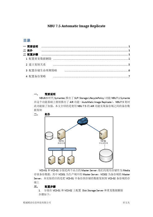
NBU 7.5 Automatic Image Replicate目录一简要说明 (1)二拓扑 (1)二配置步骤 (1)1 配置重复数据删除 (1)2 建立复制关系 (5)3 配置存储生命周期策略 (6)4 配置备份策略 (7)一、简要说明NBU6.5时代Symantec推出了SLP(Storage LifecyclePolicy)功能NBU7.1 Symante 在这个功能基础上继续推出了AIR功能(AutoMatic Image Replicate),NBU7.5则对此功能做了加强,本文介绍的是使用NBU 7.5的AIR功能实现备份域之间的备份数据复制二、VCS-01和VCS-02分别是两个站点的Master Server,他们均使用存储作为Media 存放备份数据,其中VCS01为生产域中的Master Server,VCS02为备份域的MasterServer,本实验的目的是把VCS-01中备份到存储的数据复制到VCS-02备份域的存储上三、配置步骤1.分别在VCS-01和VCS-02上配置Disk Storage Server和重复数据删除步骤如下:下面用户名和密码部分填写VCS-01的administrators组的成员下面填写配置去重的Storage和DataBase的路径,可以分开存放,也可以放在一起建立Disk Pool其中目的端VCS-02上此处可以选择”Limit I/O streams”为2 ,防止overload按照向导一直进行下去,直到建立Storage Unite 2.在源端建立域之间的关系填写目的端的主机名和Administrator的用户名密码3.配置生命周期策略如下步骤在原机上建立首先建立一个Backup类型的操作然后再在Backup这个操作之上建立Replicate类型的操作最终结果如下:如下是在目标机上操作只建立一个Inport动作即可完成后结果如下:注:原机和目标机的Storage Lifecycle Name必须是相同的4.在原机建立备份Policy(如果是单向复制,不需要在目标机上建立任何复制相关的策略)Policy的建立如下图,使用的Storage要选择定义好的生命周期的名字,其余和普通策略相同原机有如下的backup作业和Replicate作业发起目标机有如下的Inport作业发起注:AIR不能设定Schedule,规划复制的发起时间,但可以手工暂时禁用SLP,AIR 启用之后默认在备份策略完成半个小时后发起Replicate操作,完成之后对端开始Inport 操作。
CMX868
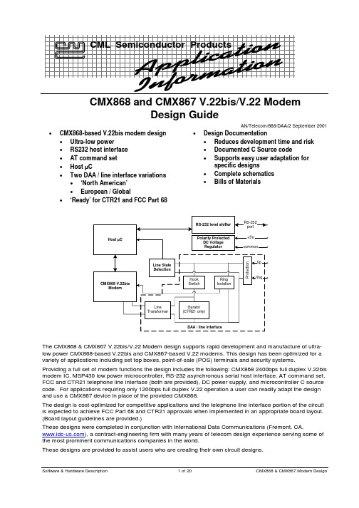
CMX868 and CMX867 V.22bis/V.22 ModemDesign GuideAN/Telecom/868/DAA/2 September 2001Software & Hardware Description 1 of 20 CMX868 & CMX867 Modem Design•CMX868-based V.22bis modem design • Ultra-low power• RS232 host interface • AT command set • Host µC• Two DAA / line interface variations• ‘North American’ • European / Global• ‘Ready’ for CTR21 and FCC Part 68•Design Documentation• Reduces development time and risk • Documented C Source code• Supports easy user adaptation forspecific designs• Complete schematics • Bills of MaterialsThe CMX868 & CMX867 V.22bis/V.22 Modem design supports rapid development and manufacture of ultra-low power CMX868-based V.22bis and CMX867-based V.22 modems. This design has been optimized for a variety of applications including set top boxes, point-of-sale (POS) terminals and security systems.Providing a full set of modem functions the design includes the following: CMX868 2400bps full duplex V.22bis modem IC, MSP430 low power microcontroller, RS-232 asynchronous serial host interface, AT command set, FCC and CTR21 telephone line interface (both are provided), DC power supply, and microcontroller C source code. For applications requiring only 1200bps full duplex V.22 operation a user can readily adapt the design and use a CMX867 device in place of the provided CMX868.The design is cost-optimized for competitive applications and the telephone line interface portion of the circuit is expected to achieve FCC Part 68 and CTR21 approvals when implemented in an appropriate board layout. (Board layout guidelines are provided.)These designs were completed in conjunction with International Data Communications (Fremont, CA, ), a contract-engineering firm with many years of telecom design experience serving some of the most prominent communications companies in the world.These designs are provided to assist users who are creating their own circuit designs.Table Of ContentsSection Page1.Introduction (3)1.1Support for CMX868 and CMX867 Devices (3)1.2Support for FCC Part 68 and CTR21 (3)1.3CMX868 (3)1.4CMX867 (4)2.Design Hardware (4)2.1Introduction (4)2.2Telephone Line State Detection (4)2.2.1On/Off Hook Detect Operation (5)2.2.2Intrusion / E911 Detect Operation (5)2.3Host Processor and CMX868 (5)2.4Line Interface Circuit (DAA) (5)2.4.1‘CTR21 Circuit’ (5)2.4.2‘FCC Circuit’ (6)3.Schematics (7)4.BOMs – Bills Of Materials (9)5.Firmware (11)5.1Compiler Switches (11)5.2Firmware Modes (11)5.3Interrupts (13)5.4Timers (13)5.5Source Code Functions (13)5.6Basic AT Commands (15)5.7CMX868 Specific AT Commands (17)5.8S Registers (17)CML does not assume any responsibility for the use of any circuitry described. No IPR or circuit patent licences are implied. CML reserves the right at any time without notice to change the said circuitry and product specifications.Software & Hardware Description 2 of 20 CMX868 & CMX867 Modem Design .Software & Hardware Description 3 of 20 CMX868 & CMX867 Modem Design.1. IntroductionThis V.22bis modem design is based on the CMX868 V.22bis modem IC. It includes an RS232 serial port host interface and an AT command set for convenient operation in a variety of embedded and standalone applications. 1.1Support for CMX868 and CMX867 DevicesThe CMX867 and CMX868 are multi-standard modem ICs, identical with the exception that the CMX867 does not support 2400bps V.22bis signaling. This allows 1200bps V.22 designs to be created using the CMX867 and later upgraded via simple modification to support faster V.22bis signaling using the CMX868, if desired. This design focuses on the CMX868 and includes V.22bis specific firmware for user convenience. If desired, a user may create a V.22 modem design from this design by replacing the CMX868 with a CMX867 and removing V.22bis specific firmware. 1.2Support for FCC Part 68 and CTR21FCC Part 68 and CTR21 are regulatory standards that modem designs must often satisfy. While CTR21 designs generally can satisfy FCC Part 68 requirements they can include components that are not necessary for FCC-only applications. This design includes schematics and bills of materials for both ‘CTR21’ and ‘FCC’ type designs.Please refer to these regulations for detailed descriptions of their requirements.1.3 CMX868Features Applications• V.22bis 2400/2400bps QAM• V.22, Bell 212A 1200/1200 or 600/600bps DPSK • V.23 1200/75, 1200/1200, 75, 1200bps FSK • Bell 202 1200/150, 1200/1200, 150, 1200bps FSK • V.21 or Bell 103 300/300bps FSK • DTMF/Tones Transmit and Receive • Extremely Low Power:3.5mA/3V, 6.5mA/5V typical •‘Powersave’ Standby Mode• Cable TV Set Top Box (STB) • Telephone Telemetry Systems • Remote Utility Meter Reading • Security Systems• Industrial Control Systems • Electronic Cash Terminals • Pay-Phones•Modem Links with Caller IDLINEThe CMX868 is a multi-standard modem for use in telephone based information and telemetry systems. Control of the device is via a simple high-speed serial bus, compatible with most types of µC serial interface. The data transmitted and received by the modem is also transferred over the same serial bus. On-chipprogrammable Tx and Rx USARTs meeting the requirements of V.14 are provided for use with asynchronous data and allow unformatted synchronous data to be received or transmitted as 8-bit words.The CMX868 can transmit and detect standard DTMF and modem calling and answer signals or user-specific programmed single or dual tone signals. A general purpose Call Progress signal detector is also included. Flexible line driver and receive hybrid circuits are integrated on chip, requiring only passive external components to build a 2 or 4-wire line interface.Software & Hardware Description 4 of 20CMX868 & CMX867 Modem Design.The device also features a hook switch relay drive output and a Ring Detector circuit which continues tofunction when the device is in Powersave mode, providing an interrupt which can be used to wake up the host µController when line voltage reversal or ringing is detected.The CMX868 operates from a single 2.7 to 5.5V supply over a temperature range of -40°C to +85°C and is available in 24-pin TSSOP, SOIC and DIP packages. 1.4 CMX867The CMX867 is identical to the CMX868 described in section 1.3, above, with the exception that the CMX867 does not support V.22bis signaling. This makes the CMX867 upward compatible with the CMX868.2. Design Hardware2.1 IntroductionThe modem hardware is implemented using an CML CMX868 multi-standard modem chip and aTexas Instruments MSP430F149 low power microcontroller. Using V.22bis signaling the modem can communicate at a maximum data rate of 2400 bits per second, full duplex, over a telephone line.Figure 1, below, shows a block diagram of the circuit. (Note the gyrator circuit is required only for the ‘CTR21’ version.)Figure 1, Function Block DiagramTelephone Line State Detection, Host Processor and CMX868 and CTR21 gyrator circuit sections are described below in more detail. 2.2Telephone Line State DetectionTelephone line state detection indicates whether a phone line is on or off hook. It also resolves when a parallel telephone extension is taken off hook after the modem has started using the line.U4 and its external components provide a difference amplifier with a gain of 1/22 with an output DC offset of 1.65V to condition the tip/ring differential voltage to develop the line-in-use signal. This signal is applied to the MSP430F149 µC ADC input that measures it to resolve the telephone line state.A full-wave rectifier precedes the differential amplifier and makes all differential tip/ring input voltages positive. This system resolves differential input voltages over a range of ~5VDC to ~18.5VDC with common mode voltages of up to ~40V. U4 must be a single supply, low input bias current, opamp.Note that 22Mohm resistors R10 and R13 provide galvanic isolation between tip/ring and circuit common by virtue of their very high impedance. Accordingly, layout spacing requirements for ‘network side’ printed circuit board traces and components must be applied to R10 and R13 and their physical terminals. However, theirSoftware & Hardware Description 5 of 20CMX868 & CMX867 Modem Design.‘circuit side’ (not ‘network side’) traces need not maintain ‘network side’ spacing because they are sufficiently isolated from tip/ring. 2.2.1On/Off Hook Detect OperationWhen the phone is on-hook, the tip/ring voltage magnitude is typically 48VDC. When a parallel phone goes off-hook this voltage normally drops below 18VDC depending on the connected loop resistance. The modem will not use the line if it is already being used as indicated by a tip/ring voltage below 18VDC.Before the modem goes off hook a reading of the line-in-use signal is performed using the MSP 430F149 ADC. If the measured value is greater than 18VDC at tip/ring (greater than 2.47VDC at the input to the ADC) this indicates the phone line is on hook (available) and the modem takes the line off hook.If the measured value is less than 18VDC (less than 2.47VDC at the input to the ADC) this indicates the line is already in use in which case the modem will not take the line off hook. 2.2.2Intrusion / E911 Detect OperationWhen the modem is using the phone line some applications prefer it go back on hook when an additionalextension is taken off hook. The purpose of this behavior is to release the phone line to allow a person to take control of the line and place a phone call e.g. to place an emergency 911 call (U.S.).Taking a parallel extension off hook when the line is being used by the modem causes the tip/ring voltage to quickly drop ~5% of its prior value. This rapid relative drop is used to resolve when a parallel extension ‘intrusion’ occurs.The modem’s off hook tip/ring voltage reference is established by reading the line-in-use voltage with the MSP430F149ADC, three seconds after the modem goes off hook. Thereafter, line-in-use is measured once each second. If the voltage drops more than ~5% this indicates a parallel extension has gone off hook so the modem drops its connection to defer to the parallel extension user.Note that ADC measurements are corrected by subtracting 1.65V in firmware prior to checking for 5% changes. (This corrects for the +1.65VDC added to input signals by the differential amplifier.) 2.3Host Processor and CMX868An MSP430F149 microcontroller is used. This device has a built features integrated Flash (64K), RAM (2K bytes), six 14-bit ADC inputs, and generous digital I/O. Alternative microcontrollers with similar features are available and suitable for use with the CMX868.A distinguishing feature of the MSP430F149 is its low power mode that draws 3µA of supply current when operating from a 32kHz crystal. This characteristic complements the CMX868’s very low power requirements. If desired, the MSP430F149 can act as both the CMX868 host and user application host, typical of embedded applications. This design includes a serial port interface driver and AT command processing to implement a ‘desktop modem’ application.Communication between the MSP430F149 and the CMX868 (U5) is via a C-BUS (also known as SPI) serial chip bus to reduce signals and simplify host programming.Header J3 is the JTAG programming port to load the firmware into the MSP430F149 processor for convenient program development. 2.4Line Interface Circuit (DAA)The line side circuit is a direct access arrangement to properly connect the modem to the telephone line. Components ISO1 and ISO2 provide an isolated ring detect interface and an isolated hook switch.Two DAA circuits are provided. One is for ‘FCC’ operation and the other is for ‘CTR21’ operation. While the ‘CTR21 circuit’ is also suited for ‘FCC’ operation, its parts count is higher and so should be used when CTR21 requirements must be satisfied. 2.4.1 ‘CTR21 Circuit’This section refers to schematic: LOW POWER MODEM WITH RS232, MICROPROCESSOR & DAA (DRY TRANSFORMER), Rev 1.84.The CTR21 gyrator circuit (not required in the ‘FCC circuit’) formed by Q1, R20, R22, R23, R24, C32, and D12 is a DC current sink with a current vs. tip/ring voltage DC response per CTR21 requirements. R20, R22 and R24 form a bias network for Q1 that adjusts the bias according to tip/ring voltage, when that voltage is low enough that D12 does not conduct. When the tip/ring voltage becomes high enough zener diode D12 conducts and clamps to 5.6VDC. This limits the Q1 bias and so limits its collector current so total circuit current is limited to below 60mA per CTR 21.Software & Hardware Description 6 of 20 CMX868 & CMX867 Modem Design.C32, 1.0 µF, provides a low pass characteristic in the current vs. tip/ring voltage gyrator response so the gyrator’s impedance at modem signaling frequencies is sufficiently high and conforms to CTR 21requirements. This prevents the gyrator from loading and damping modem signaling voltages/currents. This gyrator circuit has been successfully applied in multiple designs that are CTR 21 certified. Please refer to ETSI document TBR 21 January 1998 for additional information on CTR 21 requirements. 2.4.2 ‘FCC Circuit’This section refers to schematic: LOW POWER MODEM WITH RS232, MICROPROCESSOR & DAA (WET TRANSFORMER), Rev 1.84.The ‘FCC circuit’ is formed from the ‘CTR21 Circuit’ by taking the following three actions:1. Remove the CTR21 gyrator components (C32, D12, R20, R22, R23, R24, and Q1).2. Replace capacitor C27 with a short.3. Replace the SET0902 ‘dry’ line transformer with a Midcom 671-8001 wet line transformer. (Similarwet line transformers with UL 60950 ratings or similar characteristics may be considered if required for specific applications. Midcom 82111 and Datatronics LM72019 transformers may be of interest.)S o f t w a r e & H a r d w a r e D e s c r i p t i o n 7 o f 20 C M X 868 & C M X 867 M o d e m D e s i g n.3. S c h e m a t i c sF i g u r e 2, 'F C C ' S c h e m a t i cS o f t w a r e & H a r d w a r e D e s c r i p t i o n 8 o f 20 C M X 868 & C M X 867 M o d e m D e s i g n.F i g u r e 3, 'C T R 21' S c h e m a t i cS o f t w a r e & H a r d w a r e D e s c r i p t i o n9 o f 20 C M X 868 & C M X 867 M o d e m D e s i g n.4.B O M s – B i l l s O f M a t e r i a l sB i l l s o f m a t e r i a l s a r e p r o v i d e d f o r b o t h t h e ‘FC C ’ a n d ‘C T R 21’ s c h e m a t i c s . S e c t i o n 2.4.2, p g . 6, p r o v i d e s a d e t a i l e d d e s c r i p t i o n o f t h e i r d i f f e r e n c e s .T a b l e 1, ‘F C C ’ B i l l o f M a t e r i a l sS c h e m a t i c P a r t N u m b e r L o c a t i o n C o m p o n e n t N a m e D e s c r i p t i o n M a n u f a c t u r e r M f g P a r t N u m b e r Q t y B R 2 R J -11 c o n n e c t i o n D i o d e B r i d g e S m a l l s i g n a l d i o d e , 1A , 1000V , D O -41 p k g M i c r o C o m m e r c i a l 1N 4007 4 C 12, C 16, C 18, C 20, C 29, C 30 l i n e -i n -u s e c k t & v a r i o u s C a p a c i t o r 0.1u F , 16V , s u r f a c e -m o u n t V e n k e l C 0603X 7R 160-104K N E 6 C 17, C 21 N e a r R J -11 j a c k C a p a c i t o r C e r a m i c , 1000p F , 3000V , X 7R , 10%, S M D 1206 p k g P a n a s o n i c -E C G E C K -D 3F 102K B P 2 C 19 x 868 P /S d e c o u p l i n g C a p a c i t o r 10u F , 16V , a l u m i n u m e l e c t r o l y t i c , 20% P a n a s o n i c -E C G E C E -A 1C K A 100 1 C 22, C 25 x 868 x t a l c k t C a p a c i t o r 22p F , 50V V e n k e l C 0603C O G 500-220J N E 2 C 23 x 868 R T c k t C a p a c i t o r 0.33u F , 16V V e n k e l C 0603Y 5V 160-334Z N E 1 C 24 R i n g d e t e c t o r i n p u t C a p a c i t o r 0.1u F , 250V V e n k e l C 1206X 7R 251-104K N E 1 C 26 x 868 R X A F /B C a p a c i t o r 100p F , 50V V e n k e l C 0603C O G 500-101J N E 1 C 28 x 868 T X A f e e d b a c k C a p a c i t o r 0.015u F , 16V V e n k e l C 0603X 7R 160-153K N E 1 D 6 I n p u t t o l i n e -i n -u s e c k t Z e n e r d i o d e 3.3V , 0.5W , 5% M i c r o s e m i 1N 5226B -T 1 D 9 R i n g d e t e c t o r i n p u t Z e n e r d i o d e 22V , 500m W , 5% M i c r o s e m i 1N 5251B 1 D 11 R i n g d e t e c t o r i n p u t D i o d e 400V , 1A , r e c t i f i e r M i c r o C o m m e r c i a l C o . 1N 4004 1 F 2 R J -11 c o n n e c t i o n F u s e 125V , 0.375A , f a s t b l o w , s u r f a c e m o u n t L i t t e l f u s e I n c . 429.375W R 1 I S O 1 R i n g d e t e c t o r O p t o c o u p l e r 2.5k V i s o l a t i o n v o l t a g e , s i n g l e c h a n n e l N E C P S 2801-1 1 I S O 2 H o o k s w i t c h S o l i d s t a t e r e l a y 1 F o r m A S S R , 3750V i s o l a t i o n S o l i d S t a t e O p t r o n i c s A D 6C 111-H 1 J 4 t e l e p h o n e l i n e c o n n e c t i o n T e l e p h o n e C o n n e c t o r S i d e e n t r y , 6-4 c o n t a c t s , u n s h i e l d e d , n o p a n e l s t o p s o r f l a n g e A M P 555979-1 0 R 8, R 9 j u s t a b o v e l i n e -i n -u s e c k t R e s i s t o r 2M , 1/16W , 5% V e n k e l C R 0603-16W -205J T 2R 10, R 13 i n p u t t o l i n e -i n -u s e c k t R e s i s t o r 22M , 1/16W , 5% V e n k e l C R 0603-16W -226J T 2 R 11 h o o k s w i t c h c k t R e s i s t o r 1k , 1/16W , 5% V e n k e l C R 0603-16W -102J T 1 R 12 o u t p u t o f l i n e -i n -u s e a m p l i f i e r R e s i s t o r 1M , 1/16W , 5% V e n k e l C R 0603-16W -105J T 1 R 14 x 868 R T c k t R e s i s t o r 470k , 1/16W , 5% V e n k e l C R 0603-16W -474J T 1 R 15 R i n g d e t e c t o r (I S O 1) i n p u t R e s i s t o r 10k , 1/16W , 5% V e n k e l C R 0603-16W -103J T 1 R 16, R 18, R 19 V a r i o u s R e s i s t o r 100k , 1/16W , 5% V e n k e l C R 0603-16W -104J T 3 R 17 x 868 R D p i n p u l l d o w n R e s i s t o r 20k , 1/16W , 5% V e n k e l C R 0603-16W -203J T 1 R 21 x 868 T X A f e e d b a c k R e s i s t o r 470, 1/16W , 5% V e n k e l C R 0603-16W -471J T 1 R V 1 R J -11 c o n n e c t i o n P r o t e c t i o n D i o d e S i d a c t o r , 275V , s u r g e s u p p r e s s o r T e c c o r E l e c t r o n i c s I n c . P 3100S A _R P 1 R V 2 t r a n s f o r m e r c k t P r o t e c t i o n D i o d e T r a n s i e n t v o l t a g e s u p p r e s s o r , 68V , 600W , u n i -d i r e c t i o n a l C r y d o m C o . P 6K E 68A 1 T 1 i n t e r f a c e b e t w e e n l i n e & x 868 C o u p l i n g T r a n s f o r m e r W e t , t h r o u g h h o l e , i m p e d a n c e r a t i o 600Ω:470Ω (p r i m a r y :s e c o n d a r y ) M i d c o m 671-8001 1 U 4 L i n e i n u s e c i r c u i t S i n g l e S u p p l y O p A M P S i n g l e c h a n n e l , r a i l -t o -r a i l , l o w v o l t a g e , l o w p o w e r o p a m p N a t i o n a l S e m i c o n d u c t o r L M V 301 1 Y 2 C M X 868 c r y s t a l C r y s t a l L o w p r o f i l e , M e t a l C a n , T h r o u g h H o l e , 11.0592M h z , 50p p m t o l e r a n c e , 50p p m s t a b i l i t y , 18p f L o a d c a p C i t i z e n H C 49U S 11.0592M B B J T R 1S o f t w a r e & H a r d w a r e D e s c r i p t i o n10 o f 20 C M X 868 & C M X 867 M o d e m D e s i g n.T a b l e 2, ‘C T R 21’ B i l l o f M a t e r i a l sS c h e m a t i c P a r t N u m b e r L o c a t i o n C o m p o n e n t N a m e D e s c r i p t i o n M a n u f a c t u r e r M f g P a r t N u m b e r Q t y B R 2 R J -11 c o n n e c t i o n D i o d e B r i d g e S m a l l s i g n a l d i o d e , 1A , 1000V , D O -41 p k g M i c r o C o m m e r c i a l 1N 4007 4 C 12, C 16, C 18, C 20, C 29, C 30, C 32 v a r i o u s C a p a c i t o r 0.1u F , 16V , s u r f a c e -m o u n t V e n k e l C 0603X 7R 160-104K N E 7 C 17, C 21 N e a r R J -11 j a c k C a p a c i t o r C e r a m i c , 1000p F , 3000V , X 7R , 10%, S M D 1206 p k g P a n a s o n i c -E C G E C K -D 3F 102K B P 2 C 19 x 868 P /S d e c o u p l i n g C a p a c i t o r 10u F , 16V , a l u m i n u m e l e c t r o l y t i c , 20% P a n a s o n i c -E C G E C E -A 1C K A 100 1 C 22, C 25 x 868 x t a l c k t C a p a c i t o r 22p F , 50V V e n k e l C 0603C O G 500-220J N E 2 C 23 x 868 R T c k t C a p a c i t o r 0.33u F , 16V V e n k e l C 0603Y 5V 160-334Z N E 1 C 24 R i n g d e t e c t o r i n p u t C a p a c i t o r 0.1u F , 250V V e n k e l C 1206X 7R 251-104K N E 1 C 26 x 868 R X A F /B C a p a c i t o r 100p F , 50V V e n k e l C 0603C O G 500-101J N E 1 C 27 x f o r m e r i n p u t C a p a c i t o r 10u F , 50V , a l u m i n u m e l e c t r o l y t i c , 20% P a n a s o n i c -E E U E E U -F C 1H 100L 1 C 28 x 868 T X A f e e d b a c k C a p a c i t o r 0.015u F , 16V V e n k e l C 0603X 7R 160-153K N E 1 D 6 g y r a t o r c i r c u i t Z e n e r d i o d e 3.3V , 0.5W , 5% M i c r o s e m i 1N 5226B -T 1 D 9 R i n g d e t e c t o r i n p u t Z e n e r d i o d e 22V , 500m W , 5% M i c r o s e m i 1N 5251B 1 D 11 R i n g d e t e c t o r i n p u t D i o d e 400V ,1A , r e c t i f i e r M i c r o C o m m e r c i a l C o . 1N 4004 1 D 12 I n p u t t o l i n e -i n -u s e c k t Z e n e r d i o d e 5.6V , 0.5W , 5% M i c r o s e m i 1N 5232B -T 1 F 2 R J -11 c o n n e c t i o n F u s e 125V , 0.375A , f a s t b l o w , s u r f a c e m o u n t L i t t e l f u s e I n c . 429.375W R 1 I S O 1 R i n g d e t e c t o r O p t o c o u p l e r 2.5k V i s o l a t i o n v o l t a g e , s i n g l e c h a n n e l N E C P S 2801-1 1 I S O 2 H o o k s w i t c h S o l i d s t a t e r e l a y 1 F o r m A S S R , 3750V i s o l a t i o n S o l i d S t a t e O p t r o n i c s A D 6C 111-H 1 J 4 t e l e p h o n e l i n e c o n n e c t i o n T e l e p h o n e C o n n e c t o r S i d e e n t r y , 6-4 c o n t a c t s , u n s h i e l d e d , n o p a n e l s t o p s o r f l a n g e A M P 555979-1 0 Q 1 g y r a t o r c k t D a r l i n g t o n t r a n s i s t o r N P N D a r l i n g t o n , 200V , 600m A , 2W , S O T -223 p k g C e n t r a l S e m i c o n d u c t o r C Z T 2000 1 R 8, R 9 j u s t a b o v e l i n e -i n -u s e c k t R e s i s t o r 2M , 1/16W , 5% V e n k e l C R 0603-16W -205J T 2R 10, R 13 i n p u t t o l i n e -i n -u s e c k t R e s i s t o r 22M , 1/16W , 5% V e n k e l C R 0603-16W -226J T 2 R 11 h o o k s w i t c h c k t R e s i s t o r 1k , 1/16W , 5% V e n k e l C R 0603-16W -102J T 1 R 12 o u t p u t o f l i n e -i n -u s e a m p l i f i e r R e s i s t o r 5.1M , 1/16W , 5% V e n k e l C R 0603-16W -515J T 1 R 14 x 868 R T c k t R e s i s t o r 470k , 1/16W , 5% V e n k e l C R 0603-16W -474J T 1 R 15 R i n g d e t e c t o r (I S O 1) i n p u t R e s i s t o r 10k , 1/16W , 5% V e n k e l C R 0603-16W -103J T 1 R 16, R 18, R 19 V a r i o u s R e s i s t o r 100k , 1/16W , 5% V e n k e l C R 0603-16W -104J T 3 R 17 x 868 R D p i n p u l l d o w n R e s i s t o r 20k , 1/16W , 5% V e n k e l C R 0603-16W -203J T 1 R 20 g y r a t o r c k t R e s i s t o r 4.7k , 1/16W , 5% V e n k e l C R 0603-16W -472J T 1 R 21 x 868 T X A f e e d b a c k R e s i s t o r 470, 1/16W , 5% V e n k e l C R 0603-16W -471J T 1 R 22, R 24 g y r a t o r c k t R e s i s t o r 10k , 1/16W , 5% V e n k e l C R 0603-16W -103J T 2 R 23 g y r a t o r - D a r l i n g t o n e m i t t e r R e s i s t o r 30, 1W , 5% V e n k e l C R 2512-1W -300J T 1 R V 1 R J -11 c o n n e c t i o n P r o t e c t i o n D i o d e S i d a c t o r , 275V , s u r g e s u p p r e s o r T e c c o r E l e c t r o n i c s I n c . P 3100S A _R P 1 T 1 i n t e r f a c e b e t w e e n g y r a t o r & x 868 C o u p l i n g T r a n s f o r m e r D r y , S M T , V .34b i s r a t e d , i m p e d a n c e r a t i o 600Ω:301Ω (p r i m a r y :s e c o n d a r y ) T a i p e i M u l t i p o w e r E l e c t r o n i c s C o . S E T 0902 1 U 4 L i n e i n u s e c i r c u i t S i n g l e S u p p l y O p A M P S i n g l e c h a n n e l , r a i l -t o -r a i l , l o w v o l t a g e , l o w p o w e r o p a m p N a t i o n a l S e m i c o n d u c t o r L M V 301 1 Y 2 C M X 868 c r y s t a l C r y s t a l L o w p r o f i l e , M e t a l C a n , T h r o u g h H o l e , 11.0592M h z , 50p p m t o l e r a n c e , 50p p m s t a b i l i t y , 18p f L o a d c a p C i t i z e n H C 49U S 11.0592M B B J T R 15. FirmwareThe firmware is authored in the C programming language using IAR 430 Embedded Workbench Kit V1.24A under Windows 95/98/NT for the Texas Instruments MSP 430 microcontroller family (PC Host), available from IAR Systems Software Inc. ( ).The use of the C language makes the firmware readable and permits it to be readily ported to other microcontrollers, if desired.The firmware provided allocates 1kbytes of RAM to stack space (approximately 25% of which is used), 404 bytes of RAM variable space and 14.1 kbytes of ROM (flash) code space.Firmware source code will be made available at provided for downloading from our web site. 5.1 Compiler SwitchesThe firmware supports a variety of hardware configurations and firmware features. Compiler switches are used to conditionally compile needed code. Setting the compiler switches in the header file LwPwr430.h according to Table 3, below, enables compilation of the code required for this design.Table 3, Compiler SwitchesFeatures Compiler Switches FirmwareSwitchSettingEcho all chars after a <cr> back to same modem. 80 char buffer.MXCommEcho Off Sends/Receives chars to/from phone line to/from an RS232 port.Rs232Comm YesMonitors for Line SurrenderA/D active , After off-hook 3 seconds measure voltage- RefVoltage. Then every 1 second if( ( (RefVoltage * 0.95) < measured voltage )) then drop the callA_DActiveSurrender YesMonitors for Line ShareA/D active , before going off-hook measure A/D voltage. If (StartVoltage > 1.5V) then go off-hookA_DActiveShare Yes[This code is applicable only if Key Pad is present]‘#’ starts phone number, next ‘#’ indicates dial phone number.‘*’ indicates start phone number over KeyPadAttached OffMSP430 & CMX868Low Power mode when not in use SleepOk Off Switch for selectable Rs232 rate 1200/2400 P4.7BaudSwitch Yes5.2 Firmware ModesThe modem firmware operates in the modes depicted in Figure 4, below.• Power OnMSP430 powers up and initializes the CMX868 registers and then enters the Wait for Event mode. If Sw1-1 is ON the modem is set to 1200 baud rate. If Sw-1-1 is OFF the modem is set to 2400 baud rate.• Wait for Event ModeMSP430 waits for either a Ring Detect from the CMX868 or AT Command input from the RS-232 port. Whichever event occurs first causes the associated function to be executed.• Modem Baud Rate ModeIn response to either a ring detect from the CMX868 or dialing an outbound call (to connect with another modem) this mode attempts to negotiate a connection at 2400bps or 1200bps with the remote modem. (If the modem is set to 1200 baud the negotiated baud rate will be similarly 1200.) If the baud rate is successfully negotiated, theMSP430 goes to Transfer Mode. If the baud rate is not successfully negotiated, the MSP430 goes back to Wait for Event Mode.• Transfer ModeData is sent to and from the phone line and the terminal connected at the RS-232 port. A transition to the Wait for Event Mode occurs when either the phone call is disconnected or a parallel extension is taken off hook. A transition to AT Command mode occurs when the +++ escape sequence is entered at the RS-232 port and, in this case, a return to Transfer mode will occur if an ATO command is entered at the RS-232 port.• AT Command ModeAccept basic AT commands and act on them. After done with AT Command return to Wait for Event Mode. If AT Command is a dial command first check phone line to determine if it is already in use. If the phone line is not in use dial call and go to Modem Baud Rate Mode.Figure 4, Firmware ModesAt any given time the modem is either (1) connected or (2) not connected to a remote modem. DATAXFER is a variable that indicates this condition (1 = connected to a remote modem). Similarly, at any given time the modem ’s RS232 port is transferring either (1) AT commands and responses or (2) Tx and Rx data pumped over the phone line. ATCMDMODE is a variable that indicates this condition (1 = AT commands). Table 4, below, describes the firmware modes and related variables.Table 4, Firmware Modes and Related VariablesVariable ValueATCMDMODE DATAXFER Current Mode Prior ModeDescription0 0 Modem Baud RateanyA call has been initiated or received and the modem is negotiating a connection with a remote modem.0 1 Transfer any Modem is connected to a remote modem and data is being transferred.1 0 Wait for Event NOT TransferMode Mode that awaits either an incoming call or local entry of an AT command.1 0 AT Command Wait for EventModeMode to process an AT command that was entered when in Wait for Event mode.11AT CommandTransfer ModeMode to process an AT command that was entered when in Transfer mode.。
_IC5141_Calibre_MMSIM安装
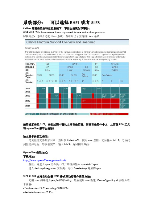
系统部分:可以选择RHEL或者SLESCaliber需要安装在特定的系统下,不然会出现如下警告:WARNING: This linux release is not supported for use with caliber products.解决方法:选择合适的Linux系统,图中列出了支持的Linux系统按照提示安装SLES,安装过程中确认主语言是英语,副语言是简体中文,从而使EDA工具和openoffice都不会出错!独立显卡的驱动安装:拷贝驱动文件到家目录,然后按Ctrl+Alt+F1,使用root登陆,之后输入init 3,之后找到驱动并运行,等安装完毕,输入init 5,返回图形界面。
Openoffice安装方式:下载地址:/download/解压,并进入rpm文件夹,打开终端并输入rpm –ivh *.rpm进入desktop-integration文件夹,运行freedesktop对应的rpmSLES 11 SP2支持自动加载NTFS格式移动存储介质的方法:先用root终端进入/etc/hal/fdi/policy,然后使用vim新建10-ntfs-3g-policy.fdi并输入以下内容:<?xml version="1.0" encoding="UTF-8"?><deviceinfo version="0.2"><device><match key="volume.fstype" string="ntfs"><merge key="volume.fstype" type="string">ntfs-3g</merge><merge key="volume.policy.mount_filesystem" type="string">ntfs-3g</merge><append key="volume.mount.valid_options" type="strlist">locale=</append></match></device></deviceinfo>然后再建立preferences.fdi并输入以下内容:<?xml version="1.0" encoding="UTF-8"?> <!-- -*- SGML -*- --><!--Some examples how to use hal fdi files for system preferencesYou can either uncomment the examples here or put them in a seperate .fdifile.--><deviceinfo version="0.2"><!--The following shows how to hint gnome-volume-manager and other programsthat honor the storage.automount_enabled_hint to not mount non-removable media.--><device><match key="storage.hotpluggable" bool="false"><match key="storage.removable" bool="false"><merge key="storage.automount_enabled_hint" type="bool">false</merge></match></match></device></deviceinfo>最后运行如下代码:/etc/init.d/haldaemon restart去下载最新的ntfs-3g源文件包ntfs-3g_ntfsprogs-****.tgz 解压,进入到解压文件夹并开启终端,在终端中依次输入:./configuremakemake install (此命令必须以root执行)等执行完毕,NTFS格式的移动硬盘就能像U盘一样自动挂载!IC5141部分:需要:base包和USR6 update包IC5141_bse包:ed2k://|file|Cadence.Base.IC5141.Lnx86.3CDs[.ck].rar|1201102747|A4DE108A291CC6BDD86D8E46D3E5 A677|h=PWYDUTUBIMHDVZ2EDLNMRNAKGAVIWJFA|/USR6_update包:/viewthread.php?tid=219912&highlight=USR6安装软件:解压和放置IC5141_base包和USR6_update包到/home/kury/cadence_install,文件夹分别命名为base和update。
Keil与Proteus安装联调操作(完美版)

1.安装Proteus Version 7.1 SET71UP。
2.包括安装破解文件MAXIM_LICENCE.lxk。
3.安装补丁文件patch,注意要在安装目录下补丁。
或者将文件夹BIN下:ARES/ISIS/LICENCE.DLL/PROSPICE.DLL文件夹ELECTRA下:ELECTRA文件夹MODELS下:AVR.DLL/KEYPAD.DLL/LCDALPHA.DLL/LCDPIXEL.DL L/LEDMPX.DLL/MCS8051.DLL//PIC12C5.DLL/PIC12C6.DLL/PIC12F6.DLL/pic16f6.DLL/PIC18.DLL/READOU T.DLL/VTERM.DLL的文件复制到安装目录相应的文件覆盖。
4.安装汉化菜单:Proteus 7.01 SP2 ARES的汉化菜单放到……Program Files\Labcenter Elect ronics\Proteus 7 Professional\BIN目录下。
Proteus 7.01 SP2 ISIS的汉化菜单放到……Program Files\Labcenter Electro nics\Proteus 7 Professional\BIN目录下。
5.完成Proteus安装。
6.安装keil C518.08 uVision3 setup。
7.进入Keil uVision3界面。
点File > license management打开Keil_lic-v3.2 注册机产生LICO 将其复制填入NEW LICENSE ID中,同时复制COMPUTER I D或者通过KEGGEN产生填入NEW LICENSE ID中。
8.Keil 与Proteus连接,连接开始必须在roteus安装目录下VDM51.dll文件复制到Keil安装目录的\C51\BIN 目录中,但新版本中没有,所以必须下载安装补丁vdmagdi.exe,则在Keil安装目录的\C51\BIN 目录中有文件:VDM51.dll同时还需下载一破解文件PROSPICE.dll替换\Proteus 6 Professional\BIN目录下的相同文件(新版本的Proteus可能不需要)。
中兴交换机配置

一、系统的启动过程如下。
1、上电后,首先进行硬件启动,当硬件检测无误后,管理终端上出现下列信息:Welcome to use ZTE eCarrier!!Copyright(c) 2004-2006, ZTE Co。
, Ltd.System Booting..。
.。
CPU: S3C45010 ARM7TDMIBSP version: 1.2/0Creation date: Feb 11 2004, 09:37:01Press any key to stop auto-boot。
..72、出现上述信息后,等待大约7 秒,用户可以在这段时间内按任意键进入boot 状态,修改启动参数.当系统在规定时间未检测到用户输入时,系统便开始自动加载版本,并提示下列信息:auto—booting。
..boot device : secEndunit number : 0processor number : 0host name : tigerfile name : vxWorksinet on ethernet (e) : 10.40.92。
106host inet (h) : 10。
40.92.105flags (f) : 0x80Attaching to TFFS.。
done。
Loading version:/kernel.。
.1459932 + 75292 + 6358852Starting at 0x1656e0...Attaching interface lo0。
.。
done(省略)Welcome !ZTE Corporation。
All rights reserved.login:adminpassword:*********3、系统启动成功后,出现提示符login:,要求输入登录用户名和密码,缺省用户名是admin,密码是zhongxing。
二、配置开始工作1.打开超级终端,输入连接的名称,如ZXR10,并选择一个图标。
HiIVE Tools User Guide_cn

日期 2016-01-11
版本 00B01
修改描述 初始版本
文档版本 00B01 (2016-01-11)
海思专有和保密信息 版权所有 © 深圳市海思半导体有限公司
ii
HiIVE 工具使用指南
目录
目录
1 ANN、SVM——模型转化工具 ................................................................................................... 1
2.5 Caffe 依赖库 3——Boost C++安装与配置.................................................................................................. 19 2.5.1 Boost 安装包下载 ................................................................................................................................ 19 2.5.2 Boost 依赖库安装 ................................................................................................................................ 19
博世 D7212 使用说明书
Control PanelD7212Release Notes for Version 7.00March 20071.0 IntroductionAlthough the D7212 (expanded version) Control Panel is no longer manufactured (replaced by the D7212G), Firmware Update Kits (P/N: D7299-0700) are available for this product. Refer to theD9412G/D7412G Program Entry Guide (P/N: 47775D or later) when programming a D7212 Control Panel.2.0 RequirementsTable 1: Handlers Supported for Version 6.90and LaterHandler Version Changes 9000MAIN 1.15∗No changes since version 6.30RADXUSR1 1.06∗Updated to support GV2 Series Control PanelsRADXPNTS 1.08∗Updated to support GV2 Series Control PanelsRADXSKED 1.04∗Updated to support GV2 Series Control PanelsRADXAUX1 1.07∗Updated to not support GV2 Series Control Panels∗Newer versions are available but are not required for the D7212 Control Panel.For handlers with new prompts, refer to theD9412G/D7412G Program Entry Guide (P/N: 47775D or later).To acquire an update for your D5200 Programmer, call the Bosch Security Systems Handler Update System toll-free at (800) 657-4584. Make a separate call for each handler.3.0 Version 7.00 Release NotesCorrection in Version 7.00Changes allow RPS workstations located on a private network behind a router or firewall to communicate with control panels outside of that network. No special router or firewall settings are required. The control panels support Port Address Translation (PAT) for networks that require it.4.0 Previous Version 6.90 ReleaseNotes4.1 Corrections in Version 6.90Enhanced Communication TroubleWhen a Route Group is configured with an IP destination in the primary path and a telephone number in the backup path, a break in the Network Link Integrity annunciates locally.When an Enhanced Communication Troublecondition occurs, it generates a system-wide trouble message (COMM TRBL SDI ##). The new troubleD7212The trouble condition is also sent through a backup path to the central station as Communication Trouble SDI ##, using the same virtual address numbers as the trouble messages. The communication trouble event also creates new Modem IIIa 2 messages that thecentral station might need to add to their automation software. Refer to Events 157 to 160 in the D6600 Computer Interface Manual (P/N: 4998122703) for the details of central station data changes. Unsupported Point TypePreviously, if the value of 11 was used with RADXPNTS version 1.06 or later when configuring the Point Index parameters, the control panel might not operate as expected. This condition is corrected so that the control panel responds to a P# Type value of 11 as a disabled point.5.0 Previous Version6.80 ReleaseNotes5.1Corrections in Version 6.805.1.1Local Event ReportingSeveral changes in this release prevent the controlpanel from sending local alarm events intermittently to the central stations. All local alarm events now remain local. 5.1.2Ethernet Link IntegrityFor UL 1610 Line Security (formerly Grade AA) Intrusion System installations and for UL 864 Commercial Fire installations, use the parametersshown in Table 2 when configuring the Heartbeat Poll. For additional details, refer to Programming PathNumbers and IP Addresses for Enhanced Communications in the D9412G/D7412G Program Entry GuideTable 2: Parameters for Heartbeat PollConfiguration in Version 6.801Number of IP Paths Poll Rate (sec) ACK Wait Time (sec)Number of Retries1 30 62 to 19 1 30 8 2 to 12 1 30 10 2 to 8 1 30 12 2 to 5 1 30 14 2 to3 1 60 6 2 to 14 1 60 8 2 to 8 1 60 10 2 to5 1 60 12 2 1 752 102 32 1 906 2 to 9 1 90 8 2 to 4 1 90 10 2 1 120 6 2 to 4 1 145 522 752 82 323 752 62 324 75252321 The parameters in this table are for Version 6.80 only . 2Recommended settings for the corresponding number of IP paths.5.2 Enhancements in Version6.80Summary Fire Relay SustainWhen the Silent Alarm Relay for Area 2 isprogrammed with 24, the Summary Fire Alarm Relay remains active until all Fire Alarms are cleared from the keypad display. The default operation is consistent with the Summary Fire Relay operation in Version 6.60 and older. This feature provides a method of maintaining fire strobes after the alarm bells are silenced.5.3 Known Issue in Version6.80When a Route Group is configured with an IP destination in the primary path and a telephone number in the backup path, a break in the Network Link Integrity does not annunciate locally.D72126.0 Previous Version 6.70 ReleaseNotesEnhancement in Version 6.70Arming Scope RestrictionsWhen the Silent Alarm Relay for Area 3 isprogrammed with 59, some prompts in the FunctionTable 3: Arming Scope RestrictionsMenu Function Function NumberDisabled Prompt Disarm Menu 1 DISARM ALL?Master Arm Delay 2 MASTER ARM ALL? Master Arm Instant3ARM INSTANT ALL?7.0Previous Version 6.60 Release Notes7.1Corrections in Version 6.60The changes made to the version 6.60 firmware affect only control panels with the ground fault detection circuit: the G-model control panels. Because the D7212 Control Panel does not have the ground fault detection circuit, this firmware upgrade does not change the control panel’s function.7.2Known Issues in Version 6.60•When a faulted local point is force armed, the central station should receive a Forced Close report for that point. The control panel does not send Forced Close reports for faulted local points. •If a local and a non-local point are faulted and force armed, the control panel does not send Forced Armed, Forced Point, or Forced Close Reports for the non-local point. A point is a local point if configured as follows: • Local While Armed : Yes •Local While Disarmed : Yes8.0 Previous Version 6.50 ReleaseNotesCorrections in Version 6.50Intermittent RF Low Battery eventsIn versions 6.30 and 6.40, Points 1 through 8 generate intermittent RF Low Battery events when devices connected to the on-board points change very quickly from normal to off-normal conditions. Firmware version 6.50 corrects this issue.When an RF Low Battery condition occurs on atransmitter, RF Low Battery appears on the D1255 or D1260 Keypad’s display. To determine whichtransmitter has the low battery condition, select one of the following: •View Log? function from the Service Menu (99 + ENT) on the keyboard, or•Diagnostics function, using the D8125INV. Refer to the D8125INV Operation and Installation Guide (P/N: 49690) for details.If the event is transmitted to the central station, the point number is included in the transmission.D72129.0 Previous Version 6.40 ReleaseNotes9.1Enhancements in Version 6.40Enabling the D1260 in a D7212 Control Panel 1. To enable D1260 Keypads, set the commandcenter menu item to Yes for the command center addresses where the D1260s reside.• In the Command Center Assignments section, the prompt is CC#EnhanceCmdCtr . •In the COMMAND CENTER (9000MAIN) section in RPS, the prompt is EnhancedCommand Center .Figure 1: Enhanced Command Center Prompt inRPS2. When power is applied, each D1260 checks thefirmware revision number that resides in the control panel. For each D1260 to work, theDisplay Revision (Command 59) must be enabled and not passcode protected. Refer to Figure 2 on page 4.•In the D5200, this function is located at: 9000MAIN USER INTERFACE Cmd Center FunctionsDisplay Rev •In RPS (Figure 2), this function is located at: USER INTERFACE Command Center FunctionsFigure 2: Enable Display Revision Prompt in RPS3. Before exiting RPS, reset the control panel aftercompleting an RPS programming session:A.Click the Reset Panel checkbox B. Click OK .Refer to Figure 3.Figure 3: End Session Dialog BoxFigure 4: Keypad DisplayD72129.2Corrections in Version 6.40Duplicate Events Do Not Report under Comm Fail ConditionsVersion 6.40 corrects the following problem:When a Comm Fail condition occurs in Route Group 1, Route Group 2, or both, D7212 does not send duplicate events to Route Groups 3 and 4 whenduplicate events are programmed for Route Groups 2, 3, 4, or all groups.Support for D1260 Not in Version 6.30 as Stated in LiteratureThe D9412G/D7412G Program Entry Guide(P/N: 47775D) and the D7212 Release Notes for v6.30 (P/N: 34699N) state incorrectly that Alpha V Command Center (keypad) support is available in version 6.30.Only version 6.40 or higher can support the D1260 Alpha V Command Center (keypad) Watchdog Reset EventsVersion 6.40 corrects Watchdog Reset eventsgenerated when a SKED is used to arm a disabled area or a Closing Window and Auto Close prompt is set to Yes (in Area Wide Open/Close ). BFSK FormatBefore version 6.40, the control panel did not send Burglary Restoral reports when using the BFSK communication format. Version 6.40 corrects this issue.Fail to Execute EventsBefore version 6.40, Fail To Execute events incorrectly identified the serial device interface (SDI) device associated with the event. Version 6.40 corrects this issue.Programming Point Indexes for Points 240 – 247 In version 6.30 for the D7412G and D7212 Control Panels, if you use a D5200 to assign point Points 240 through 247, the control panel ignores these points and mistakenly shows missing conditions. Version 6.40 corrects this issue.9.3Known Issues in Version 6.40Disconnecting Battery during Walk Test Causes D1260 to Stop RespondingWhen the control panel’s battery is disconnected and then reconnected during a Walk Test, the D1260 stops responding and displays Retrieving panel info . The control panel must be restarted to clear the keypad.Areas Armed to “All on instant” Do Not Show Area Text in D1260 View Area StatusWhen arming areas to All on Instant, area text does not appear when using the View Area Status menu function on the D1260. BFSK FormatSupervisory and Fire Supervisory events cannot be29.4 Programming TipsNetCom CommunicationsIn applications where both the primary and backup paths are programmed to send an IP address, the Path # Poll Rate value for the backup IP address should be set to 0. In the D9412G/D7412G Program Entry Guide (P/N: 47775), refer to: •Routing and Enhanced Routing for information about primary and backup paths.•Enhanced Communications in the RADXAUX1Handler section for information about Path # Poll Rate .D7212NotesD7212 NotesD7212© 2007 Bosch Security Systems, Inc.130 Perinton Parkway, Fairport, NY 14450-9199 USACustomer Service: (800) 289-0096; Technical Support: (888) 886-6189 F01U034872-02Release Notes for Version 7.003/07D7212Page 8 of 8。
7750SR配置方法

7750SR路由器配置规范V2.1上海贝尔阿尔卡特股份有限公司互联网事业部二零零六年十一月目录1.概述 (4)2.系统基本配置 (6)2.1.层次化命令结构 (6)2.2.在CLI中获得帮助 (7)2.3.硬件板卡配置 (8)2.4.设备名称配置 (9)2.5.系统时间配置 (9)2.6.NTP配置 (9)2.7.主备卡切换配置 (10)2.8.AAA配置(登录用户) (11)3.端口配置 (13)3.1.Loopback端口配置 (13)3.2.GE端口配置 (13)3.3.POS端口配置 (14)3.4.端口镜像配置 (15)4.安全配置 (18)4.1.ACL配置 (18)4.2.防攻击配置 (18)5.网管配置 (24)5.1.网管地址配置 (24)5.2.TELNET配置 (24)5.3.FTP配置 (25)5.4.SNMP (25)5.5.SYSLOG (26)5.6.配置备份 (27)5.7.SSH配置 (27)Flow备份 (28)6.路由配置 (29)6.1.黑洞路由配置 (29)6.2.静态路由配置 (29)6.3.OSPF配置 (29)6.4.ISIS配置 (33)6.5.BGP配置 (35)7.业务配置 (40)7.1.专线业务配置(IES配置) (40)7.2.MPLS VPN业务配置 (41)7.2.1P路由器配置 (41)7.2.2PE路由器配置(VPRN) (44)7.2.3PE路由器配置(VPLS) (46)8.7750SR常用维护命令 (49)1.概述阿尔卡特7750SR路由器是业内第一个专为高级互联网和虚拟专用网络(VPN)业务而设计和优化的IP/MPLS业务路由器。
阿尔卡特7750SR有三种尺寸可供选择:单槽、7槽和12槽,可提供具有卓越性能和高密度的各种接口。
作为目前业内最具扩展性的路由器平台,阿尔卡特7750SR具有为高效传送基于服务等级协议(SLA)的业务而设计的软件和硬件架构,因此阿尔卡特7750SR不仅仅是强大的互联网路由器,更是一个灵活、强大的业务供应平台。
- 1、下载文档前请自行甄别文档内容的完整性,平台不提供额外的编辑、内容补充、找答案等附加服务。
- 2、"仅部分预览"的文档,不可在线预览部分如存在完整性等问题,可反馈申请退款(可完整预览的文档不适用该条件!)。
- 3、如文档侵犯您的权益,请联系客服反馈,我们会尽快为您处理(人工客服工作时间:9:00-18:30)。
补丁程序召回通知
Update Manager 会定期与 VMware 联系,下载关于补丁程序召回、新修 复程序和警报的通知。 默认情况下,“Notification Check Schedule”(通知检查调度) 呈选中状态。 在收到补丁程序召回通知时,Update Manager 将会: 在通知选项卡中生成通知 不再对任何主机应用已召回的补丁程序:
• • •
创建和附加基准。 扫描清单对象。 修复清单对象。
VMware vSphere:安装、配置、管理 – 修订版 A
13-21
版权所有 © 2011 VMware Inc。保留所有权利
要点
Update Manager 可修补和更新 ESXi 5.0 主机与早期版本的 ESX/ESXi、 虚拟机、模板和虚拟设备。 Update Manager 可通过实时更新系统以及降低环境中系统的多样性来 减少安全漏洞。 Update Manager 不再修补客户操作系统或客户操作系统中运行的应用 程序。
VMware vSphere:安装、配置、管理 – 修订版 A
13-12
版权所有 © 2011 VMware Inc。保留所有权利
扫描更新
扫描可以针对基准或基准组评估清单对象。
可手动或通过调度任务自动执行扫描。
VMware vSphere:安装、配置、管理 – 修订版 A
13-13
版权所有 © 2011 VMware Inc。保留所有权利
13-9
版权所有 © 2011 VMware Inc。保留所有权利
基准和基准组
基准由一个或多个补丁程序、扩展模块或升级程序组成。
基准有五种类型: 主机补丁程序 主机扩展模块 主机升级程序 虚拟机硬件或 VMware Tools 升级 虚拟设备升级程序
Update Manager 包含 多个默认基准。 基准组由多个基准组成: 可包含按类型制定的升级基准以及 一个或多个补丁程序和扩展基准
VMware vSphere:安装、配置、管理 – 修订版 A
13-22
版权所有 © 2011 VMware Inc。保留所有权利
• • •
创建和附加基准。 扫描清单对象。 修复清单对象。
VMware vSphere:安装、配置、管理 – 修订版 A
13-4
版权所有 © 2011 VMware Inc。保留所有权利
Update Manager
借助 Update Manager,您可以对 VMware® ESXi™ 主机、虚拟机硬件、 VMware Tools 和虚拟设备的补丁程序和版本进行集中式自动管理。
集群的修复选项
修复集群中的主机时, 必须暂时禁用某些特定的集群功能: vSphere Distributed Power Management、 vSphere HA、FT。
您可以生成一个报 告,用于在修复前 找出问题。
VMware vSphere:安装、配置、管理 – 修订版 A
13-17
版权所有 © 2011 VMware Inc。保留所有权利
VMware vSphere:安装、配置、管理 – 修订版 A
13-2
版权所有 © 2011 VMware Inc。保留所有权利
重要说明
随着时间推移,您的 VMware vSphere® 环境可能会发生变化,可能是硬 件或软件配置发生更改,或者是对软件进行了更新或修补。从可管理性和 扩展性角度考虑,您应该采用有序、可控的系统化方式将这些更改实施到 vSphere 环境中。
Update Manager 可降低安全风险: 保证系统实时更新,从而减少漏洞的数量。 避免出现许多利用早期漏洞的安全漏洞。 减少环境中的系统多样性:
• •
减轻管理难度 降低安全风险
VMware vSphere:安装、配置、管理 – 修订版 A
13-5
版权所有 © 2011 VMware Inc。保留所有权利
一个主机补丁程 序被添加到此基 准中。
VMware vSphere:安装、配置、管理 – 修订版 A
13-11
版权所有 © 2011 VMware Inc。保留所有权利
附加基准
要查看合规性信息并修复清单对象,需要先将基准或基准组附加到对象。 为了提高效率,可以将基准附加到容器对象,而不是附加到单个对象。
查看合规性
在本示例中,通过 扫描发现了两个不 合规的主机。
扫描之后,可先转储补丁程序和 更新程序,以后再修复。
VMware vSphere:安装、配置、管理 – 修订版 A
13-14
版权所有 © 2011 VMware Inc。保留所有权利
修复对象
您可以修复虚拟机、模板、虚拟设备和主机。 您可以立即执行修复,也可以调度在稍后执行。
补丁程序管理
第 13 单元
版权所有 © 2011 VMware Inc。保留所有权利
您的位置
课程简介 虚拟化简介 虚拟机 VMware vCenter Server 配置和管理虚拟网络 配置和管理虚拟存储 管理虚拟机
数据保护 访问权限和身份验证控制 资源管理和监视 高可用性 可扩展性 补丁程序管理 安装 vSphere 组件
Update Manager 的功能
支持跨平台将 VMware ESX® 升级到 ESXi
自动下载补丁程序: 最初仅下载信息 调度为按可配置的时间间隔定期下载 请访问下列下载源:
• •
要下载 ESXi 补丁程序,请访问:https:// 要下载第三方补丁程序,请访问:第三方补丁程序的下载源 URL
创建基准和基准组
扫描: 扫描清单系统,检查基准遵从性。
修复: 可自动修补非当前清单系统。 可减少 VMware Tools 更新之后的重启次数
VMware vSphere:安装、配置、管理 – 修订版 A 13-6
版权所有 © 2011 VMware Inc。保留所有权利
Update Manager 的组件
VMware vSphere:安装、配置、管理 – 修订版 A
13-8
版权所有 © 2011 VMware Inc。保留所有权利
配置 Update Manager 设置
默认情况下,启用所有补丁 程序源。如果需要,还可以 添加其他补丁程序源。
修改 Update Manager 配 置属性。
VMware vSphere:安装、配置、管理 – 修订版 A
UM + DRS!源自维护模式13-19
版权所有 © 2011 VMware Inc。保留所有权利
VMware vSphere:安装、配置、管理 – 修订版 A
练习 20
在本练习中,您将安装、配置和使用 Update Manager。 1. 安装 Update Manager。 2. 在 vSphere Client 中安装 Update Manager 插件。 3. 修改集群设置。 4. 配置 Update Manager。 5. 创建补丁程序基准。 6. 附加基准并扫描更新。 7. 将补丁程序转储到 ESXi 主机。 8. 修复 ESXi 主机。
安装过程中需要提供的信息: vCenter Server 主机名、用户名和密码 可选择的数据库:使用默认或现有的数据库 Update Manager 端口设置:
•
主机名、端口、代理设置(如有必要)
要将补丁程序下载到其中的目标文件夹及位置
要安装 Update Manager 客户端,请: 在 vSphere Client 中安装 Update Manager 扩展插件。
VMware vSphere:安装、配置、管理 – 修订版 A
13-15
版权所有 © 2011 VMware Inc。保留所有权利
维护模式和修复
关闭或挂起虚拟机 适用于 PXE 引导的 ESXi 5.0 的选项
VMware vSphere:安装、配置、管理 – 修订版 A
13-16
版权所有 © 2011 VMware Inc。保留所有权利
数据库 服务器
VMware vCenter Server™ 系统
主机
vCenter Server 数据库
可选的下载 服务器
补丁程序 数据库 补丁程序 数据库
Update Manager 服务器
装有 Update Manager 插件的 VMware vSphere Client™
Internet VMware 补丁程序源 第三方补丁 程序源
VMware vSphere:安装、配置、管理 – 修订版 A
13-7
版权所有 © 2011 VMware Inc。保留所有权利
安装 Update Manager
Update Manager 必须安装在 64 位计算机上。 要进行安装,请启动 VMware vCenter 安装程序,然后单击“VMware vSphere Update Manager”。
VMware vSphere:安装、配置、管理 – 修订版 A
13-20
版权所有 © 2011 VMware Inc。保留所有权利
回顾学员的学习目标
您应当能够执行以下任务: 介绍 Update Manager。 列出 Update Manager 的安装步骤。 使用 Update Manager:
•
补丁程序在数据库中被标记为已召回。
从补丁程序存储库中删除该补丁程序二进制文件 不从 ESXi 主机上卸载召回的补丁程序:
•
相反,Update Manager 会等待并应用更新的补丁程序,使主机符合规范。
VMware vSphere:安装、配置、管理 – 修订版 A
13-18
版权所有 © 2011 VMware Inc。保留所有权利