MBD101中文资料
开关量输入采集器使用说明书讲解
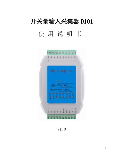
1开关量输入采集器D101 使用说明书V1.0尊敬的用户:衷心感谢您选用深圳市聚贤达科技有限公司的产品。
本手册主要介绍开关量输入采集器D101的工作原理、技术指标、主要功能、安装调试及使用与维护等内容。
为了使您更好地使用我们的产品,请您仔细阅读本手册,在应用中如果您有任何问题和要求,或需要相关技术支持,可以与我们的销售单位联系,我们将及时给予回应。
2目录1.前言 (5)2.内容 (5)3.要求 (5)4.警示 (5)5.概述 (6)6.技术参数 (6)7.产品外观 (7)7.1装置运行指示灯 (8)7.2各通道指示灯 (8)7.3产品接线端子定义 (8)8.产品原理和功能 (10)9.安装操作 (11)9.1外形尺寸 (11)9.2机柜安装 (12)310.常见问题及解决 (14)11.售后服务 (14)12.技术培训 (14)13.其他声明 (14)14.设备清单 (15)41.前言请在使用本产品前仔细阅读各章节。
2.内容本手册主要介绍开关量输入采集器D101的工作原理、技术指标、主要功能、安装调试及使用与维护等内容,由资深的专业技术人员编写,是设备使用维护的必备资料。
3.要求在任何情况下,都不应该由不具备专业资历或未经培训的人员来操作。
使用者必须是具有电气设备安装和操作经验的专业技术人员。
由不具备资历的人员对设备进行设置和操作,或不按照本书中有关规定进行包装、储运、安装和连接电源,都将可能导致设备损坏。
4.警示运输或存储不当会对设备造成损害;5供电电压错误会对设备造成损坏或引起火灾;如发现无法解决的问题,请及时与我公司联系或将设备送回我公司处理,请勿自行拆装维修。
5.概述开关量输入采集器D101是用于计算机机房、重要设备间、配线间、网络机柜、服务器机柜、配电柜、粮库、重要仓库以及其他室内场合的开关量数据采集装置。
采集开关量,装置能通过RS-485接口将信号传送给中央监控设备。
6.技术参数供电电源:DC10V~30V;通道: 16;LED显示:与16通道一一对应;开关量输入电平:干接点:逻辑电平0:接地;67 逻辑电平1: 断开;干接点有效距离: 最大500m ; D/I 用于计数器通道: 16;输入频率: 100Hz ;16位 : 0~65535;电源 :功耗: 0.9W ;尺寸规格:124mm×80mm×33mm;7.产品外观指示灯和按键功能说明7.1装置运行指示灯正常:正常工作时指示灯按1Hz的频率闪亮;故障:常亮、常灭、快闪为故障。
MPDRX103S;中文规格书,Datasheet资料
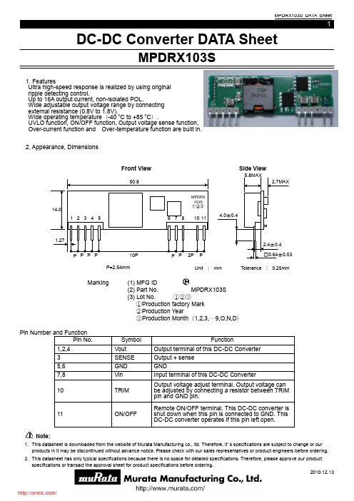
Note:1. This datasheet is downloaded from the website of Murata Manufacturing co., ltd. Therefore, it ’ s specifications are subject to change or our products in it may be discontinued without advance notice. Please check with our sales representatives or product engineers before ordering.DC-DC Converter DATA SheetMPDRX103S1. FeaturesUltra high-speed response is realized by using original ripple detecting control.Up to 16A output current, non-isolated POL.Wide adjustable output voltage range by connecting external resistance (0.8V to 1.8V). Wide operating temperature (-40 o C to +85 oC ).UVLO function, ON/OFF function, Output voltage sense function, Over-current function and Over-temperature function are built in. 2. Appearance, DimensionsFront ViewSide ViewP=2.54mm(1) MFG ID (2) Part No. MPDRX103S (3) Lot No. ①②③ ①Production factory Mark ②Production Year③Production Month (1,2,3,…9,O,N,D )MarkingNote:1. This datasheet is downloaded from the website of Murata Manufacturing co., ltd. Therefore, it ’ s specifications are subject to change or our products in it may be discontinued without advance notice. Please check with our sales representatives or product engineers before ordering. 3. Block Diagram4. Environmental Conditions4 .1 Operating Temperature Range -40 to +85 °C (Temperature gradient ≦10°C /H ) 4 .2 Storage Temperature Range -40 to +85 °C (Temperature gradient ≦25°C /H ) 4 .3 Operating Humidity Range 20% ~ 85%(No water condenses in any cases.)4 .4 Storage Humidity Range 10% ~ 90% (Unpacked condition. No water condenses in any cases.) 4 .5 Maximum Wet Bulb39°C5. Absolute Maximum Rating 5 .1 Input Voltage Range10.8V – 13.2V 5 .2 ON/OFF Pin InputVoltage Range-0.3V to Vin+0.3V7,81,2,410115,63Note:1. This datasheet is downloaded from the website of Murata Manufacturing co., ltd. Therefore, it ’ s specifications are subject to change or our products in it may be discontinued without advance notice. Please check with our sales representatives or product engineers before ordering. 6. Characteristicso※CautionThe above electrical characteristics are guaranteed with the condition that the impedance of the input voltage source is sufficiently low as shown in section 9. Connecting an input inductance or using an input power supply with output inductance may cause an unstable operation of this device. Please check the proper operation of this device with the peripheral circuits on your system.Note:1. This datasheet is downloaded from the website of Murata Manufacturing co., ltd. Therefore, it ’ s specifications are subject to change or our products in it may be discontinued without advance notice. Please check with our sales representatives or product engineers before ordering.6. 2 Thermal DeratingThe above derating limits apply to this product soldered directly to 101.6*180mm*1.6mm PCB (double-sided, with 70um copper). Any adjacent parts of high temperature may cause overheating. For reliable operation, please ensure that the FET temperature of this product is maintained below 120°C and the inductor temperature is below 106°C.Note:1. This datasheet is downloaded from the website of Murata Manufacturing co., ltd. Therefore, it ’ s specifications are subject to change or ourproducts in it may be discontinued without advance notice. Please check with our sales representatives or product engineers before ordering.7. Operation in information7.1 Adjusting the Output VoltageThe output voltage can be adjusted ranging from 0.8V to 1.8V by connecting resistors between TRIM-pin (10Pin) to GND-pin (5Pin).The following equation gives the required external-resistance value to adjust the output voltage to the required Vout.Internal circuit7.2 ON/OFF ControlON/OFF functionBy using ON/OFF function, the operation of this product can be disabled without disconnection of input voltage. Sequence of a power supply system and power-saving control can be easily achieved usingthis function.ON/OFF control usageWhen ON/OFF-pins(11pin) are left open …… Output Voltage =ON When ON/OFF-pins(11pin) are connected to GND …… Output Voltage=OFFVout 0.8-5440Rtrim= -5100[ohm]RtrimNote: 1. This datasheet is downloaded from the website of Murata Manufacturing co., ltd. Therefore, it ’ s specifications are subject to change or our products in it may be discontinued without advance notice. Please check with our sales representatives or product engineers before ordering. 7.3 Output Voltage SensingBy connecting SENSE-pin to the load, output voltage drop in wiring shall be compensated.Please do NOT connect SENSE-pin to the output of LC filter that is set to the Vout line. When using this way, this product will not operate properly.7.4 Input External capacitorIt is recommended to connect a ceramic capacitor or a low-impedance electrolytic capacitor of 22μF or more at Vin terminal. Smaller input capacitor may leads to an unstable operation of this product caused by input voltagefluctuation. Please check the proper operation of it on your product when smaller input capacitor is used.7.5 Output External capacitorCeramic capacitors are recommended as output external capacitor.Using ceramic capacitors, small output variation and small ripple voltage are realized.Output capacitor should be within 47μF to 1000μF. Output capacitor shall be placed near th e output terminal. When using plural capacitors, please make sure to place a capacitor of at least 47μF near the output terminal, and place other capacitors near the load.When using LC output filter, please make sure to place a capacitor of at least 47μF near the output terminal.8. Reliability 8.1 HumidityAccording to JIS-C-0022.40 土2°C, 90 to 95%RH, 100 hours. Leave for 4 hours at room temperature.No damage in appearance and no deviation from electrical characteristics (section 6.1.).8.2 Temperature CyclesRepeat cycle 5 times. Leave 2 hours at room temp.No damage in appearance and no deviation from electrical characteristics (section 6.1.).8.3 Vibration10 to 55Hz, 1.5mm amplitude (1minute cycle), 1 hour for each of X, Y , Z directions.No damage in appearance and no deviation from electrical characteristics (section 6.1.).8.4 Mechanical Shock20G, 1 time for each X, Y , Z directions.No damage in appearance and no deviation from electrical characteristics (section 6.1.).LoadLoadNote: 1. This datasheet is downloaded from the website of Murata Manufacturing co., ltd. Therefore, it ’ s specifications are subject to change or our products in it may be discontinued without advance notice. Please check with our sales representatives or product engineers before ordering.9. Test CircuitIn the following test circuit, the initial values under item 6.1. should be met.9.1. General Measure CircuitCin : 100uF /16V (16ZL120MMRKTA6.3X11,Rubycon)(Low-impedance Electrolytic Capacitor )Cout : 100uF /6.3V (GRM32EB30J107ME16L, Murata)(Ceramic Capacitor )9.2. Ripple Voltage Measurement CircuitCoaxial cable :1.5D-2V, L=1.5mVinNote: 1. This datasheet is downloaded from the website of Murata Manufacturing co., ltd. Therefore, it ’ s specifications are subject to change or our products in it may be discontinued without advance notice. Please check with our sales representatives or product engineers before ordering. 10. Packaging Specification①Like the figure below, put the product on the conductive mat in a row. (5lines ×4columns)「 ②Pile and pack the 3 above –mentioned units at maximum.Fig1-1. Top View Product4 columnsFig1-2. S ide View1. This datasheet is downloaded from the website of Murata Manufacturing co., ltd. Therefore, it’ s specifications are subject to change or ourproducts in it may be discontinued without advance notice. Please check with our sales representatives or product engineers before ordering.Note:1. This datasheet is downloaded from the website of Murata Manufacturing co., ltd. Therefore, it ’ s specifications are subject to change or our products in it may be discontinued without advance notice. Please check with our sales representatives or product engineers before ordering.11. Production factoryKomatsu Murata Mfg.Co.,Ltd. Kanazu Murata Mfg.Co.,Ltd. Wakura Murata Mfg. Co., Ltd.分销商库存信息: MURATAMPDRX103S。
开关-温度传感器和开关选型 -中文
插入式显示表
MBD 1000 VVS no EAN no 5702423187898 订货号 060G2850
MAKING MODERN LIVING POSSIBLE
何处应用
针对温度控制和测量领域不同的应用,丹佛斯提供了丰富的温度开关和传感器产品。 选型手册上的产品为当今市场提供了最精确和可靠的选择,而它们仅是我们产品家族中 最常用的一部分。 这一系列产品覆盖了从轻工业到重工业的各种应用,其中包括:船舶、农业、供热 和卫生、空调、蒸汽动力厂以及液压等。 KP系列温度开关为干燥环境(防护等级IP33)的工业应用提供了一种紧凑和经济的 控制方案。 RT和KPS系列温度开关以高防护等级而知名,因此可以应用于潮湿的环境中。同时, KPS开关可以承受高强度振动和冲击的影响,因此它成为一些特殊环境如发动机监测领 域独一无二的选择。
0 - 40
3 - 10
30/33*
Room sensor
5702423148769
060L117166
* when mounted on wall
开关-RT系列
类型 RT 14 (capillary tube) RT 101 (capillary tube) 带毛细管的KP 61, 78, 79, 81 室内传感器KP 75 RT 101 (capillary tube) RT 101 (capillary tube) - max. reset RT 107 (capillary tube) - max. reset RT 107 (capillary tube) RT 120 (capillary tube) RT 123 (capillary tube) 设定温度 ˚C -5 - 30 25 - 90 25 - 90 25 - 90 70 - 150 70 - 150 120 - 215 150-250 可调回差 ˚C (最低-最高) 2 - 10 2.4 - 20 2.4 - 20 2.4 - 20 1.8 - 25 1.8 - 25 1.8 - 30 1.8 - 30 防护等级(IP) 66 66 66 54 54 66 66 66 毛细管长度 2m 2m 5m 2m 2m 2m 2m 2m EAN no 5702428004206 5702423119448 5702423119486 5702423119455 5702423119622 5702423119615 5702423120659 5702423120802 订货号 017-509966 017-500366 017-502266 017-500466 017-513666 017-513566 017-520866 017-522066
【微计算机信息】_可编程计算机控制器_期刊发文热词逐年推荐_20140724

科研热词 可编程控制器 plc 可编程序控制器 控制系统 造纸机械 自动控制 纺织机械 石油化工 电力传动 步进电机 印刷机械 包装机械 《plc技术应用200例》 触摸屏 现场总线 控制器 控制 可编程逻辑器件 cpld 组态软件 组态王 现场可编程门阵列 接口 可编程自动化 变频器 动态数据交换 profibus-dp can总线 高频发射机 高速计数器 高速脉冲 高温高压 驱动器 间隙调整 镗孔挖槽 金刚石 通讯 通用可编程接口 通用串行总线 远程监控 远程控制 运动控制系统 运动控制模块 运动控制 输入输出模块 软件设计 转换模块 读卡机 语法分析 试验环道 词法分析 设备控制
推荐指数 21 10 9 5 4 4 4 4 4 4 4 4 4 3 3 3 3 3 3 2 2 2 2 2 2 2 2 2 1 1 1 1 1 1 1 1 1 1 1 1 1 1 1 1 1 1 1 1 1 1 1 1
2009年 序号 1 2 3 4 5 6 7 8 9 10 11 12 13 14 15 16 17 18 19 20 21 22 23 24 25 26 27 28 29 30 31 32 33 34 35 36 37 38 39 40 41 42 43 44 45 46 47 48 49 50 51 52
2008年 序号 1 2 3 4 5 6 7 8 9 10 11 12 13 14 15 16 17 18 19 20 21 22 23 24 25 26 27 28 29 30 31 32 33 34 35 36 37 38 39 40 41 42 43 44 45 46 47 48 49 50 51 52
时序 无级调速 数据通信 数据传输 故障诊断 扩展模块 总线 彩灯控制器 开放性 开放式结构 开关磁阻电机 带式输送机 巡线机器人 定位控制 多泵制 处理系统 塞焊 图像传感器 回转窑 喷涂机器人 可编程运动控制器 可编程计算机控制器 可编程自动化控制器 可编程控制器模块 可编程多轴控制器 可编程器件 反模糊化 双向通讯 参数化编程 压缩机 医疗机器人 区域控制 动态调光 分布式系统 光电传感器 倍加福编码器 信号发生装置 位置控制 伺服电机控制 伺服电机 代码生成 人机界面 主从通讯 串行通讯 串行通信 串口扩展 中断功能 下位机 上位机 wtopcsvr.dll工具包 wincc visual c++ vhdl usb2.o
巴斯夫原油破乳剂Basorol L 101安全技术说明书

安全技术说明书页: 1/9 巴斯夫安全技术说明书按照GB/T 16483编制日期 / 本次修订: 18.12.2021版本: 4.2日期/上次修订: 07.10.2019上次版本: 4.1日期 / 首次编制: 19.11.2007产品: 原油破乳剂 Basorol L 101Product: Basorol® L 101(30434591/SDS_GEN_CN/ZH)印刷日期 01.08.20231. 化学品及企业标识原油破乳剂 Basorol L 101Basorol® L 101推荐用途和限制用途: 油田用特性化学品公司:巴斯夫(中国)有限公司中国上海浦东江心沙路300号邮政编码 200137电话: +86 21 20391000传真号: +86 21 20394800E-mail地址: **********************紧急联络信息:巴斯夫紧急热线中心(中国)+86 21 5861-1199巴斯夫紧急热线中心(国际):电话: +49 180 2273-112Company:BASF (China) Co., Ltd.300 Jiang Xin Sha RoadPu Dong Shanghai 200137, CHINA Telephone: +86 21 20391000Telefax number: +86 21 20394800E-mail address: ********************** Emergency information:Emergency Call Center (China):+86 21 5861-1199International emergency number: Telephone: +49 180 2273-1122. 危险性概述纯物质和混合物的分类:根据 GHS 标准,该产品不需要进行分类。
巴斯夫安全技术说明书日期 / 本次修订: 18.12.2021版本: 4.2产品: 原油破乳剂 Basorol L 101Product: Basorol® L 101(30434591/SDS_GEN_CN/ZH)印刷日期 01.08.2023标签要素和警示性说明:根据GHS标准,该产品不需要添加危险警示标签其它危害但是不至于归入分类:注意有关存储和操作的规定或注解,无已知特殊危害。
防腐阀门

-
-
-
1/8
163.87
7.2
1/8
196.65
8.9
1/8
229.4
10.6
1/4
1425.7 19.5
1/4
2284.1 34.9
1/4
3048
39.9
1/4
3244.7 51.9
3/8
6964.5 93.2
3/8
7439.7 105.3
3/8
14912 184.5
1/2
49161 407.4
-
目录
衬氟对夹式蝶阀-D371F4 衬氟对夹式蝶阀 衬氟截止阀-J41F46 衬氟截止阀 衬氟截止阀 衬氟手动蝶阀 衬氟放料球阀-FQ41F46 衬氟放料球阀 衬氟放料球阀-FQ41F 衬氟放料球阀 衬氟放料球阀 衬氟旋塞阀 衬氟止回阀-H41F46 衬氟止回阀 衬氟止回阀 衬氟法兰截止阀-J41F46 衬氟法兰截止阀 衬氟法兰球阀-Q41F46 衬氟法兰球阀 衬氟球阀 衬氟直流截止阀 衬氟直角截止阀-J44F46 衬氟直角截止阀 衬氟直角截止阀 衬氟立式止回阀-H42F46 衬氟立式止回阀 衬氟蓝式过滤器 衬氟蝶阀
三、材料:
阀体:铸铁、球墨铸铁、碳钢、不锈钢 阀盖:铸铁、球墨铸铁、碳钢、不锈钢 衬里:无衬里、橡胶 隔膜:橡胶 阀瓣:铸铁 气缸:铝合金、碳钢 气动薄膜:橡胶 阀杆:碳钢、不锈钢 手轮:铸铁
四、测试:
衬里层:电火花检测 试验与检验按 BS6755 标准 公称压力:PN(MPa) 阀体:PN×1.5 密封:PN×1.1
3/8
16715
212
注:1. 气动隔膜阀门尚可附装反馈信号、限位器或定位器,以适应自控、程控或调节流量的需要。 2. 气动阀门的反馈信号采用无触点传感技术。 3. 采用薄膜式气缸替代活塞式气缸,排除了活塞易损漏而导致无法启闭阀门的弊端。 4. 当气源发生故障时,可操作手轮使阀门开启。
ES1001-9PDDB1中文资料(Power-One)中文数据手册「EasyDatasheet - 矽搜」
Page
电磁兼容性(EMC).................................... 15 抗扰度环境条件.................................. 17 机械数据................................................ .................... 18 安全和安装说明........................................ 19 选项说明............................................... ............. 23 配件................................................. ........................... 32 EC-一致性声明............................................. ... 33
C S 2 5 40 -9 E R
系列................................................. ...............................小号
输出数量............................................... ......... 1,2
Eff. 输入电压
Eff. 选项
V算I一个- VI最大
[%] 20至100伏直流
[%]
77
FS1001-7R
83
FS1301-7R
77
-9
83 E , -9E
84
FS1501-7R
84
V
MB101资料
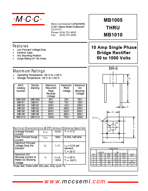
Electrical Characteristics @ 25°C Unless Otherwise Specified
Average Forward Current Peak Forward Surge Current Maximum Forward Voltage Drop Per Element IF(AV) IFSM 10.0A 150A TJ = 50°C 8.3ms, half sine
Volts Instantaneous Reverse Leakage Current - MicroAmperes versus Percent Of Rated Peak Reverse Voltage - Volts
Figure 4 Peak Forward Surge Current 200
元器件交易网
MCC
Features
• • • • Low Forward Voltage Drop Ceramic Case Any Mounting Position Surge Rating Of 150 Amps
omponents 21201 Itasca Street Chatsworth !"# $
10
150 100
86 Amps 4来自Amps50 25 0 1 4 6 8 10 20 40 60 80 100
2 Single Phase, Half Wave 60Hz Resistive or Inductive Load 0 0 25 50 75 100 150 175
2
Cycles Peak Forward Surge Current - Amperesversus Number Of Cycles At 60Hz - Cycles
- 1、下载文档前请自行甄别文档内容的完整性,平台不提供额外的编辑、内容补充、找答案等附加服务。
- 2、"仅部分预览"的文档,不可在线预览部分如存在完整性等问题,可反馈申请退款(可完整预览的文档不适用该条件!)。
- 3、如文档侵犯您的权益,请联系客服反馈,我们会尽快为您处理(人工客服工作时间:9:00-18:30)。
NOTE: MMBD101LT1 is also available in bulk packaging. Use MMBD101L as the device title to order this device in bulk.
Preferred devices are Motorola recommended choices for future use and best overall value.
Figure 1. Reverse Leakage
Figure 2. Forward Voltage
1.0
11 10 NF, NOISE FIGURE (dB) LOCAL OSCILLATOR FREQUENCY = 1.0 GHz (TEST CIRCUIT IN FIGURE 5)
C, CAPACITANCE (pF)
UHF NOISE SOURCE H.P. 349A
DIODE IN TUNED MOUNT
NOISE FIGURE METER H.P. 342A
IF AMPLIFIER NF = 1.5 dB f = 30 MHz
Figure 5. Noise Figure Test Circuit
2
Motorola Small–Signal Transistors, FETs and Diodes Device Data
SOLDERING PRECAUTIONS
The melting temperature of solder is higher than the rated temperature of the device. When the entire device is heated to a high temperature, failure to complete soldering within a short time could result in device failure. Therefore, the following items should always be observed in order to minimize the thermal stress to which the devices are subjected. • Always preheat the device. • The delta temperature between the preheat and soldering should be 100°C or less.* • When preheating and soldering, the temperature of the leads and the case must not exceed the maximum temperature ratings as shown on the data sheet. When using infrared heating with the reflow soldering method, the difference shall be a maximum of 10°C. • The soldering temperature and time shall not exceed 260°C for more than 10 seconds. • When shifting from preheating to soldering, the maximum temperature gradient shall be 5°C or less. • After soldering has been completed, the device should be allowed to cool naturally for at least three minutes. Gradual cooling should be used as the use of forced cooling will increase the temperature gradient and result in latent failure due to mechanical stress. • Mechanical stress or shock should not be applied during cooling. * Soldering a device without preheating can cause excessive thermal shock and stress which can result in damage to the device.
元器件交易网
MOTOROLA
SEMICONDUCTOR TECHNICAL DATA
Order this document by MBD101/D
Schottky Barrier Diodes
• Low Noise Figure — 6.0 dB Typ @ 1.0 GHz
0.037 0.95
0.037 0.95
0.079 2.0 0.035 0.9 0.031 0.8
inches mm
SOT–23 SOT–23 POWER DISSIPATION
The power dissipation of the SOT–23 is a function of the drain pad size. This can vary from the minimum pad size for soldering to a pad size given for maximum power dissipation. Power dissipation for a surface mount device is determined by TJ(max), the maximum rated junction temperature of the die, RθJA, the thermal resistance from the device junction to ambient, and the operating temperature, TA . Using the values provided on the data sheet for the SOT–23 package, PD can be calculated as follows: PD = TJ(max) – TA RθJA
MBD101 Rating Reverse Voltage Forward Power Dissipation @ TA = 25°C Derate above 25°C Junction Temperature Storage Temperature Range Symbol VR PF 280 2.2 TJ Tstg +150 – 55 to +150 225 1.8 mW mW/°C °C °C MMBD101LT1 Value 7.0 Unit Volts CASE 318 – 08, STYLE 8 SOT– 23 (TO – 236AB)
Thermal Clad is a registered trademark of the Berquist Company.
Motorola Small–Signal Transistors, FETs and Diodes Device Data © Motorola, Inc. 1997
1
元器件交易网 MBD101 MMBD101LT1
Figure 4. Noise Figure
LOCAL OSCILLATOR
NOTES ON TESTING AND SPECIFICATIONS Note 1 — CC and CT are measured using a capacitance bridge (Boonton Electronics Model 75A or equivalent). Note 2 — Noise figure measured with diode under test in tuned diode mount using UHF noise source and local oscillator (LO) frequency of 1.0 GHz. The LO power is adjusted for 1.0 mW. IF amplifier NF = 1.5 dB, f = 30 MHz, see Figure 5. Note 3 — LS is measured on a package having a short instead of a die, using an impedance bridge (Boonton Radio Model 250A RX Meter).
Surface mount board layout is a critical portion of the total design. The footprint for the semiconductor packages must be the correct size to insure proper solder connection interface between the board and the package. With the correct pad geometry, the packages will self align when subjected to a solder reflow process.
元器件交易网
MBD101 MMBD101LT1
INFORMATION FOR USING THE SOT–23 SURFACE MOUNT PACKAGE
MINIMUM RECOMMENDED FOOTPRINT FOR SURFACE MOUNTED APPLICATIONS
TYPICAL CHARACTERISTICS