欧姆龙继电器G7S_E
欧姆龙G2R系列继电器
4
3
2
1
8
7
6
5
IN 1 2 3 4
68以下 RY1 RY2 RY3 RY4
OUT
8.7
12 11 10 9 16 15 14 13
31以下
35以下 继电器的拆卸工具
想要开关微小负载时就用它!
G7T
备有采用交叉式双接点的输入用继电器,它拥有非常高的接触可靠性,可以用于PLC的输入。
输入用 ● 接点构造 1a
500VA, 90W
6
ܡ䌍 ⬉䆱
䆶⬉䆱
400-820-4535
᳔ᮄֵᙃ
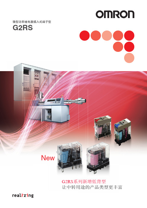
G2R-□-S
■ 性能
项目
极数
1极
2极
接触电阻*1
100mΩ
100mΩ
动作时间*2
15ms以下
复位时间*2
AC:10ms以下 DC:5ms以下(20ms以下 *3)
AC:15ms以下 DC:10ms以下(20ms以下 *3)
注1. 标准认证产品以UL/CSA、 VDE认证产品为标准。另外,与P2RF-E、 P2RF-S组合符合 “EC适合宣言”。产品带有 “CE标记”。 2. 适用的插座型号请参见下述的 “●连接插座”。 3. 表示形状的 (S)、(L)标示在线圈电压规格的后面。 (例:G2R-1-S DC24V (S), G2R-1-S DC24V (L))
250万次(10mA) 2万次(1A() 电阻负载)
输出用 ● 接点构造 1a、1b、1c
●专用插座
19以下 5-M3.5×8 带方垫圈螺钉 7+0.2
-0
71.5以下
4 12.5±0.2
35.5
9 19.5 60.5以下
高精度数字压力开关ISE70G ISE75G ISE76G ISE77G产品说明书

Instruction ManualHigh Precision Digital Pressure Switch ISE70G / ISE75G / ISE76G / ISE77GThe intended use of the pressure switch is to measure the pressure of fluid and to provide an output signal.These safety instructions are intended to prevent hazardous situations and/or equipment damage. These instructions indicate the level of potential hazard with the labels of “Caution,” “Warning” or “Danger.”They are all important notes for safety and must be followed in addition to International Standards (ISO/IEC) *1), and other safety regulations. *1)ISO 4414: Pneumatic fluid power - General rules relating to systems. ISO 4413: Hydraulic fluid power - General rules relating to systems.IEC 60204-1: Safety of machinery - Electrical equipment of machines. (Part 1: General requirements)ISO 10218-1: Manipulating industrial robots -Safety. etc.∙ Refer to product catalogue, Operation Manual and Handling Precautions for SMC Products for additional information. ∙ Keep this manual in a safe place for future reference.CautionCaution indicates a hazard with a low level of risk which, ifnot avoided, could result in minor or moderate injury.WarningWarning indicates a hazard with a medium level of riskwhich, if not avoided, could result in death or serious injury.DangerDanger indicates a hazard with a high level of risk which, ifnot avoided, will result in death or serious injury.Warning∙ Always ensure compliance with relevant safety laws and standards.∙ All work must be carried out in a safe manner by a qualified person in compliance with applicable national regulations.∙ This product is class A equipment intended for use in an industrial environment. There may be potential difficulties in ensuring electromagnetic compatibility in other environments due to conducted or radiated disturbances.∙ Do not disassemble, modify (including changing the printed circuit board) or repair. An injury or failure can result.∙ Do not operate the product outside of the specifications. Do not use for flammable or harmful fluids.Fire, malfunction or damage to the product can result.∙ Do not operate in an atmosphere containing flammable or explosive gases.Fire or an explosion can result.This product is not designed to be explosion proof. ∙ If using the product in an interlocking circuit:Provide a double interlocking system, for example a mechanical system.∙ Check the product for correct operation.Otherwise malfunction can result, causing an accident.∙ Do not touch terminals and connectors while the power is on. Otherwise electric shock, malfunction or product damage can result. ∙ Refer to the operation manual on the SMC website (URL: https:// ) for more safety instructions.2 Specifications2.1 General specifications2.2 IO-Link specifications IO-Link type Device IO-Link versionV1.1Communication speed COM2 (38.4 kbps) Min. cycle time2.3 msProcess data lengthInput Data: 2 byte, Output Data: 0 byte On request data comms. Available Data storage function Available Event function Available Vendor ID 131 (0x0083)Device IDISE70G-*-L2-* : 309 (0x0135) ISE75G-*-L2-* : 320 (0x0140) ISE76G-*-L2-* : 321 (0x0141) ISE77G-*-L2-* : 322 (0x0142)Special products (-X) might have specifications different from those shown in this section. Contact SMC for specific drawings.3.13.2 Display4 Installation4.1 InstallationWarning∙ Do not install the product unless the safety instructions have been read and understood. 4.2 EnvironmentWarning∙ Do not install in a location subject to vibration or impact in excess of the product’s specifications.∙ Do not mount in a location exposed to radiant heat that would result in temperatures in excess of the product specification.4.3 Mounting with BracketMount the bracket to the product using mounting screws supplied (M4x6 L (2 pcs)) then set the product in the required position.Tighten the bracket mounting screws to a torque of 0.76 ±0.1 N•m. Bracket A (Part No. ZS-50-A) Bracket B (Part No. ZS-50-B)4.44.5 PipingCaution∙ Before connecting piping make sure to clean up chips, cutting oil, dust etc.∙ After hand tightening, tighten the fitting using a spanner on the flat surfaces of the fitting (24 mm A/F).∙ When tightening, do not hold the upper part of the product (display) with the spanner.∙ For Rc1/4 and NPT1/4 threads the tightening torque must be 8 to 12 N•m. For G1/4 thread the tightening torque must be 4 to 5 N•m.4.6 Display Rotation∙ During installation, the upper part (display) of the product can be rotated by 336°. Take care as rotating the display with excessive force will damage the end stopper.4.7 Wiring∙ Connections should be made with the power supply turned off.∙ Use a separate route for the product wiring and any power or high voltage wiring. Otherwise, malfunction may result due to noise.∙ If a commercially available switching power supply is used, be sure to ground the frame ground (FG) terminal. If a switching power supply is connected, noise will be superimposed and will not meet the product specifications.Insert a noise filter such as a line noise filter/ferrite between the switching power supplies or change the switching power supply to the series power supply.ORIGINAL INSTRUCTIONSSpanneUpper part of productProduct No. ISE70G ISE75GISE76GISE77GApplicable fluid Fluids and Gases (non corrosive)P r e s s u r eRated pressure range 0 to 1.00 MPa 0 to 2.00 MPa 0 to 5.00 MPa 0 to 10.0 MPa Display / set pressurerange-0.105 to 1.050MPa-0.105 to 2.100 MPa -0.25 to 5.25 MPa -0.50 to10.50 MPa Minimum setting unit 0.001 MPa 0.01 MPa Proof pressure 3.0 MPa 5.0 MPa 12.5 MPa 30 MPaE l e c t r i c a lPower supply as switch output device 12 to 24 VDC ±10% with 10% Voltage ripple or less (p-p) Power supply as IO-Link device 18 to 30 VDC, including 10%voltage ripple (p-p)Current consumption 35 mA or less Protection Polarity protectionA c c u r a c yDisplay accuracy ±2% F.S.±1 digit (at ambient 25±3 o C)Repeatability±0.5% F.S.Temp. characteristics(25 o C standard) ±3% F.S.±5% F.S.S w i t c h o u t p u tOutput type NPN or PNP open collector output. Output mode Hysteresis mode, window comparator mode, error or switch output OFF.Switch operation Normal or reversed output.Max. Load current 80 mA Max. Applied voltage 30 V (NPN output)Internal voltage drop (Residual voltage) 1.5 V or less (Load current 80 mA) Delay time2.0 ms or less (for anti-chatter function:variable at 0 to 60 s / 0.01 step)Hysteresis or Window comparator mode Variable from 0 Short circuit protection ProvidedD i s p l a yUnits MPa, kPa, kgf/cm 2, bar, psiDisplay type LCDNumber of displays 3-screen display (Main display,sub display x 2)Display colour Main display: Red/Green, Sub display: OrangeNumber of display digitsMain display: 4 digits (7-segments) Sub display: 4 digits (Upper 1 digit 11-segments, 7-segments for other) Operation lightLED is ON when switch output is ON(OUT1, OUT2: Orange) Digital filterVariable from 0 to 30 s / 0.01 stepOrifice(Part no. ZS-48-A)Tighten the orifice to a torque of 1.5 ±0.1 N•m.Power supply / Output connector (M12 plug)Fitting(24 mm across flats)Part DescriptionOperation Light Displays the switch operating condition Main display Displays pressure measurement values and error codes (2 colour display). Sub display (left) Displays items (Orange)Sub display (right) Displays set values, peak and bottom values. (Orange)UP button Increases mode and ON/OFF set values. DOWN button Decreases mode and ON/OFF set values. SET button Changes the mode and confirms the settings. IO-Link status indicator light Displays OUT1 output communication status (SIO mode, start-up mode, operation mode) and the presence of communication data.Product code is displayed for 3 seconds∙ How to use connectorAlign the cable connector key groove with the product connector key to insert and rotate the knurled part of the connector.Connect the wires of the lead wire to the M12 connector as shown below. M12 Connector (code A)1) When used as a switch output device No. Name Colour Function 1 DC(+) Brown 12 to 24 VDC 2 OUT2 White Switch output 2 3 DC(-) Blue 0 V 4 OUT1 Black Switch output 12) When used as an IO-Link device No. Name Colour Function 1 L+ Brown 18 to 30 VDC 2 DO White Switch output 2 3 L- Blue 0 V4C/QBlackCommunication data (IO-Link) / Switch output 1 (SIO)Power is suppliedDefault settingsWhen the pressure exceeds the set value, the switch will be turned ON. When the pressure falls below the set value by the amount of hysteresis or more, the switch will be turned OFF.The default setting is to turn ON the pressure switch when the pressure reaches the centre of the atmospheric pressure and upper limit of the rated pressure range. If this condition is acceptable, then keep these settings.∙ 3 step setting mode (hysteresis mode)In 3 step setting mode, the set value (P_1 or n_1) and hysteresis (H_1) can be changed. Set the items on the sub display (set value or hysteresis) using the UP and DOWN button. When changing the set value, follow the operation below. The hysteresis setting can be changed in the same way.(1) Press the SET button once whenthe item to be changed is shown on the sub display. The set value on the sub display will start flashing.(2) Press the UP or DOWN button tochange the set value.When the UP and DOWN buttons are pressed and held simultaneously for 1 second or longer, the set value is displayed as [- - -], and the set value will be the same as the current pressure value automatically (snap shot function).Afterwards, it is possible to adjust the value by pressing the UP or DOWN button.(3) Press the SET button to complete the setting.The Pressure switch turns on within a set pressure range (from P1L to P1H) during window comparator mode. Set P1L, the lower limit of the switch operation, and P1H, the upper limit of the switch operation and WH1 (hysteresis) following the instructions given above.(When reversed output is selected, the sub display (left) will indicate [n1L] and [n1H].)∙ Set OUT2 in the same way.∙ Setting of the normal/reverse output switching and hysteresis/window comparator mode switching are performed using the function selection mode [F 1] OUT1 setting and [F 2] OUT2 setting.8 Simple Setting mode(1) Press and hold the SET button between 1 and 3 seconds inmeasurement mode. [SEt] is displayed on the main display. When the button is released while in the [SEt] display, the current pressure value is displayed on the main display, [P_1] or [n_1] is displayed on the sub display (left), and the set value is displayed on the sub display (right) (Flashing).(2) Change the set value using the UP and DOWN button,and press the SET button to set the value. Then, the setting moves to hysteresis setting. (The snap shot function can be used).(3) Change the set value with the UP or DOWN button,to the delay time of the switch output. (The snap shot function can be used).(4) The delay time of the switch output can be selected by pressing theUP or DOWN button at the ON and OFF point of the switch output. Delay time setting can prevent the output from chattering.The delay time can be set in the range 0.00 to 60.00 sec. in 0.01 sec. increments.(5) Press the SET button for less than 2 seconds to complete the OUT1setting. [P_2] or [n_2] is displayed on the sub screen (left). Continue with setting OUT2.Press and hold the SET button for 2 seconds or longer to complete the setting. The product will return to measurement mode. ∙ In window comparator mode, set P1L, the lower limit of the switch operation, and P1H, the upper limit of the switch operation, WH1 (hysteresis) and dtH / dtL (delay time) following the instructions given above. (when reversed output is selected, the sub display (left) will indicate [n1L] and [n1H]). ∙ Set OUT2 in the same way.9 Function Selection modeIn measurement mode, press the SET button between 3 and 5 seconds to display [F 0]. Select to display the function to be changed [F□□].Press and hold the SET button for 2 seconds or longer in function selection mode to return to measurement mode.*: Some products do not have all of the functions. If a function is not available or selected due to configuration of other functions, [- - -] is displayed on the sub display.10 Other Settings∙ Peak / Bottom value displayThe max. (min.) pressure from when power is supplied is detected and monitored. The value can be displayed on the sub display by pressing the UP or DOWN button in measurement mode. ∙ Snap Shot functionThe current pressure value can be stored to the switch output ON/OFF set point. When the set value and hysteresis are set, press the UP and DOWN button for 1 s or longer simultaneously. Then the set value of the sub display (right) shows [---], and the values corresponding to the current pressure values are automatically displayed. ∙ Zero-clear functionIn measurement mode, when the UP and DOWN buttons are pressed for 1 s or longer simultaneously, the main display shows [---] and then will reset to zero. The display will return to measurement mode automatically. ∙ Refer to the operation manual on the SMC website (URL: https// ) for further details of how to set these and other functions.11 Maintenance11.1 General MaintenanceCaution∙ Not following proper maintenance procedures could cause the product to malfunction and lead to equipment damage.∙ If handled improperly, compressed air can be dangerous.∙ Maintenance of pneumatic systems should be performed only by qualified personnel.∙ Before performing maintenance, turn off the power supply and be sure to cut off the supply pressure. Confirm that the air is released to atmosphere.∙ After installation and maintenance, apply operating pressure and power to the equipment and perform appropriate functional and leakage tests to make sure the equipment is installed correctly.How to reset the product after power cut or forcible de-energizing The setting of the product will be retained as it was before a power cut or de-energizing. The output condition is also basically recovered to that before a power cut or de-energizing, but may change depending on the operating environment.Therefore, check the safety of the whole installation before operating the product. If the installation is using accurate control, wait until the product has warmed up (approximately 10 to 15 minutes).12 Troubleshooting12.1 Error Indication If the error cannot be reset after the above measures are taken, or errorsother than the above are displayed, please contact SMC.13 Limitations of Use13.1 Limited warranty and Disclaimer/Compliance Requirements Refer to Handling Precautions for SMC Products.14 Product DisposalThis product shall not be disposed of as municipal waste. Check your local regulations and guidelines to dispose this product correctly, in order to reduce the impact on human health and the environment.15 ContactsRefer to or www.smc.eu for your local distributor/importer.URL : https:// (Global) https://www.smc.eu (Europe) SMC Corporation, 4-14-1, Sotokanda, Chiyoda-ku, Tokyo 101-0021, JapanSpecifications are subject to change without prior notice from the manufacturer. © 2021 SMC Corporation All Rights Reserved. Template DKP50047-F-085MPress the SET button once Press the SET button for 1 to 3 s Press the SET button for 3 to 5 s [3 step setting mode]Set value orhysteresis[Simple setting mode]Set value, hysteresis and delay time[Function selection mode]Change the function settings[Other settings]∙Zero clear ∙Snap lock ∙Key Lock。
欧姆龙汽车继电器G8ND系列的基本参数
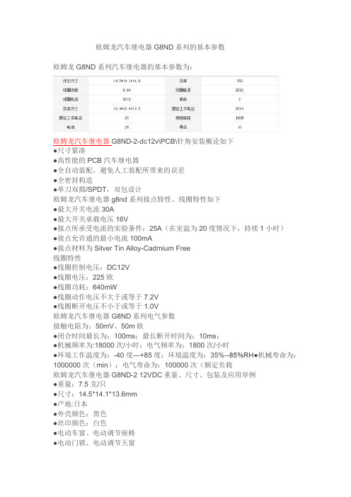
欧姆龙汽车继电器G8ND系列的基本参数欧姆龙G8ND系列汽车继电器的基本参数为:欧姆龙汽车继电器G8ND-2-dc12v\PCB\针角安装概论如下●尺寸紧凑●高性能的PCB汽车继电器●全自动装配,避免人工装配所带来的误差●全密封构造●单刀双掷/SPDT,双包设计欧姆龙汽车继电器g8nd系列接点特性、线圈特性如下●最大开关电流30A●最大开关承载电压16V●接点所承受电流的实验条件:25A(在室温为20度情况下,持续1小时)●接点允许通的最小电流100mA●接点材料为Silver Tin Alloy-Cadmium Free线圈特性●线圈控制电压:DC12V●线圈电压:225欧●线圈功耗:640mW●线圈动作电压不大于或等于7.2V●线圈断开电压不小于或等于1.0V欧姆龙汽车继电器G8ND系列电气参数接触电阻为:50mV、50m欧●闭合时间最长为:100ms;最长断开时间为:10ms;●机械频率为:18000次/小时;电气频率为:1800次/小时●环境工作温度为:-40度---+85度;环境温度为:35%--85%RH●机械寿命为:1000000次(min);电气寿命为:100000次(额定负载欧姆龙汽车继电器G8ND-2 12VDC重量、尺寸、包装及应用举例●重量:7.5克/只●尺寸:14.5*14.1*13.6mm●产地:日本●外壳颜色:黑色●丝印颜色:白色●电动车窗、电动调节座椅●电动门锁、电动调节天窗●车载冰箱●车载电气系统智能接线盒和模块的应用包装:1200只/箱管装(批量使用时,定货时需按1200的整数倍定)欧姆龙汽车电子向客户提供多种优质的汽车电子产品。
车窗自动升降系统、自动门锁、继电器等高性能产品,为提供安全、舒适的汽车生活做出贡献。
我们致力于技术的开发,生产新型的汽车电子组件,为实现更安全、更便利、更环保的人性化汽车社会而努力。
omron E2E通用接近开关 说明书
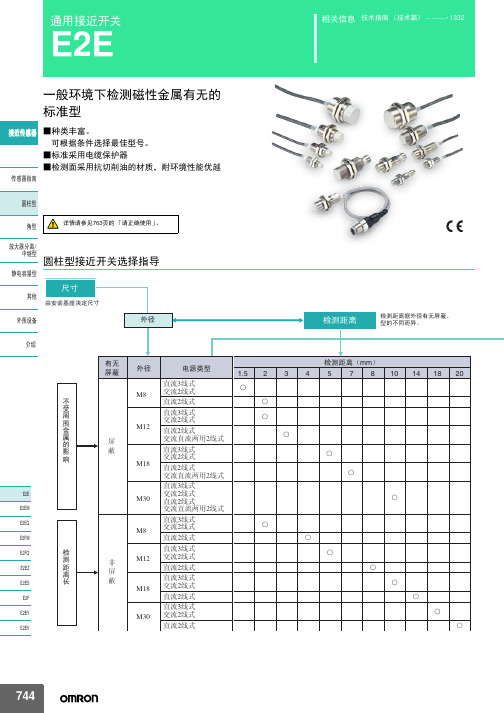
10mm 8mm
E2E-X10D1S-M1
D
——
—
E2E-X8MD1S-M1
D
——
—
M18
14mm
E2E-X14MD1S-M1
D
——
—
M30
20mm
E2E-X20MD1S-M1
D
——
—
M8
2mm
M12
ሣ㬑
M12 3mm
E2E-X2D1-M1G
A E2E-X2D2-M1G
D
E2E-X3D1-M1G *1
㾦ൟ
ᬒ఼ߚ行 Ё㒻ൟ
M30
10mm
无
M8
4mm
䴲ሣ㬑
M12
8mm
M18
14mm
E2E-X10D1-N E2E-X4MD1 E2E-X8MD1 E2E-X14MD1
*1*2*3 *2*3 *1*2*3 *1*2*3
E2E-X10D2-N E2E-X4MD2 E2E-X8MD2 E2E-X14MD2
ሣ㬑
1.5mm
E2E-X1R5E1-M3
M8 䴲ሣ㬑
M8 2mm
E2E-X2ME1-M3
输出形态PNP NO E2E-CR8B1 E2E-X1B1 E2E-C1B1 E2E-X1R5F1 E2E-X2F1 E2E-X5F1 E2E-X10F1 E2E-X2MF1 E2E-X5MF1 E2E-X10MF1 E2E-X18MF1
Ⳉ⌕2㒓ᓣ
ƻ ƻ
Ⳉ⌕3㒓ᓣ M18 Ѹ⌕2㒓ᓣ
Ⳉ⌕2㒓ᓣ
ƻ ƻ
Ⳉ⌕3㒓ᓣ M30 Ѹ⌕2㒓ᓣ
Ⳉ⌕2㒓ᓣ
ƻ ƻ
744
E2E
⬉⑤䕧ߎ Փ⫼⦃๗
欧姆龙MY继电器共用底座

一般 继电 器、 固态 继电 器
MY1、 MY2
MY (Q、 MY3 K、 H) MY4、 MYQ4
MY4Z-CBG MY2K、 MY4H
LY1、 LY2
LY
LY3
LY4
G7K
G7K-412S
G2A (K)
G2A、 G2A-434 G2AK
MK (K)
MK2P
MK3P MK2KP
插脚数
适用插座
表面
背面
E2C-GE4A E2C-GF4A
61F-GP-N8 61F-APN2
61F-UHS
61F 液位
设备
61F-HSL
61F-03B、 -04B 61F-GP-N 61F-GPN-V50 61F-GPN-BT/BC
61F-IP 61F-G1P、 -G2P
K7L
K7L-AT50/AT50D K7L-U/-UD
ܡ䌍 ⬉䆱
䆶⬉䆱 400-820-4535
᳔ᮄֵᙃ
2
种类
z 方形插座
形状 插脚数
P2RF-05 约27g
5脚
P2RF (表面连接)第8页
P2RF-05-E* 约38g
P2RF-05-S 约36g
共用插座/DIN导轨相关产品
P2R (背面连接)第10~11页
插脚数
适用插座
表面
背面
8 8PFA
11 PL
PFA 14
8 8PFA1
PYF
8 PTF PF083A PTF
5 P2RF-05□ 8 P2RF-08□ 5 P2RF-05□
5 P7TF-05
PL
PY
PT PL PT P2R-05□ P2R-08□ P2R-05□
欧姆龙继电器型号 文档 (2)
公司是欧姆龙一级代理商,价格优势明显,质量有保证,有大量库存,供货期短。
欢迎新老客户来电查询联系人:1 3 5 2 0 1 1 5 8 9 1 传0 1 0- 8 0 1 1 5 5 5 5转7 5 9 7 1 13F88L-RS173G3IV-PLKEB45P53G3JV-MANUAL3G3JZ-AB0223G3MV-A4075(YES)3G3MZ-A2004-ZV23G3MZ-A2007-ZV23G3MZ-A2015-ZV23G3MZ-A2055-ZV23G3RV-B418K-ZV13G3RV-B422K-ZV13G3RV-B4900-ZV13G3RX-A4220-Z43767-0010 MC374005-3066 UM5-3066C200H-ATT01C200H-BC101-V2C200H-CP114C200H-DA001C200H-DA002C200H-ID218C200H-ID501C200H-NC111C200H-OD501C200H-TS001C200HW-COM01C200HW-COM05-EV1C200HW-DRM21-V1C200HW-NC213C500-CE405CJ1W-OD263CP1W-20EDT1(Q)CP1W-40EDT1CPM1A-20EDT1CPM1A-40CDT-A-V1 CPM2A-20CDR-DCPM2A-20CDT-DCPM2A-30CDR-DCQM1-ID211CQM1-ME04RCQM1H-PLB21CRT1-AD04CS1D-CPU44SCS1H-CPU66HCS1H-CPU67HCS1W-BAT01CS1W-BI033CS1W-CN224CS1W-OC201CS1W-PDC55CS1W-SCU31-V1D4N-212GDRT1-232C2DRT2-AD04E2E-X10D1S DC12-24 2ME3X-DAC21-S 2ME5AZ-C3E5AZ-Q3E5AZ-R3E5CN-Q2HBT AC100-240 (Q)E5CN-R2HBT AC100-240 (Q)E5CN-R2T AC100-240 (Q)E5CZ-Q2 AC100-240E5CZ-R2MT AC100-240E5EZ-C3E6C2-CWZ6C 1024P/R 2M BY OMSG3JA-C425B AC100-240 FOR CHINA G3JA-C430B AC100-240 FOR CHINA G3JA-C437B AC100-240 FOR CHINA G3JA-D420B AC100-240 FOR CHINA G3JA-D425B AC100-240 FOR CHINA G3JA-D432B AC100-240 FOR CHINA G3JA-D451B AC100-240 FOR CHINA G3PB-535B-2N-VD DC12-24H5CN-XCN AC100-240H5F-BMKS2P DC12MKS3P-5 DC48MPT-CN550NS10-TV01B-V2R7A-CNB01S-ZR7A-CNB01SB-ZR7A-CNZ01C-ZR7D-AP04HR7D-AP08HR7D-BP01H-ZR7D-BP02H-ZR7D-BP02HH-ZR7D-BP04H-ZR7D-ZP01HR7D-ZP02HR7M-A40030-S1R7M-A75030-S1R7M-Z10030-S1ZR7M-Z20030-S1ZR88A-CNG01SB-ZR88D-GN01H-ML2-ZR88D-GN02H-ML2-ZR88D-GN04H-ML2-ZR88D-GN08H-ML2-ZR88D-GN10H-ML2-ZR88D-GN15H-ML2-ZR88D-GN20H-ML2-ZR88D-GN50H-ML2-ZR88D-GN75H-ML2-ZR88D-GT50H-ZR88D-GT75H-ZR88D-WN08H-ML2R88D-WN10H-ML2R88M-G10030H-BS2-Z R88M-G10030H-ZR88M-G1K020H-S2-Z R88M-G1K020H-ZR88M-G1K020T-BS2-Z R88M-G1K020T-S2-Z R88M-G1K020T-ZR88M-G1K030H-BS2-Z R88M-G1K030H-S2-Z R88M-G1K030H-ZR88M-G1K030T-S2-Z R88M-G1K520H-BS2-Z R88M-G1K520H-S2-Z R88M-G1K520H-ZR88M-G1K520T-BS2-Z R88M-G1K520T-S2-Z R88M-G1K520T-ZR88M-G1K530H-S2-Z R88M-G1K530T-S2-Z R88M-G20030H-BS2-Z R88M-G20030T-BS2-Z R88M-G20030T-S2-Z R88M-G2K010H-S2-Z R88M-G2K010H-ZR88M-G2K010T-S2-Z R88M-G2K010T-ZR88M-G2K020H-BS2-Z R88M-G2K020H-S2-Z R88M-G2K020H-ZR88M-G2K020T-S2-ZR88M-G2K030H-S2-Z R88M-G2K030T-S2-Z R88M-G3K010H-BS2-Z R88M-G3K010H-S2-Z R88M-G3K010H-ZR88M-G3K010T-S2-Z R88M-G3K020H-BS2-Z R88M-G3K020H-S2-Z R88M-G3K020H-ZR88M-G3K020T-S2-Z R88M-G3K020T-ZR88M-G3K030H-BS2-Z R88M-G3K030H-S2-Z R88M-G3K030H-ZR88M-G40030H-B-ZR88M-G40030H-BS2-Z R88M-G40030H-ZR88M-G40030T-BS2-Z R88M-G40030T-S2-Z R88M-G4K020H-BS2-Z R88M-G4K020H-S2-Z R88M-G4K020T-S2-Z R88M-G4K030H-BS2-Z R88M-G4K030H-S2-Z R88M-G4K510H-BS2-Z R88M-G4K510H-S2-Z R88M-G4K510T-S2-Z R88M-G5K020H-BS2-ZR88M-G5K030H-BS2-ZR88M-G5K030H-S2-ZR88M-G6K010H-BS2-ZR88M-G6K010H-S2-ZR88M-G75030H-BS2-ZR88M-G75030T-BS2-ZR88M-G75030T-S2-ZR88M-G7K515H-BS2-ZR88M-G7K515H-S2-ZR88M-G7K515T-S2-ZR88M-G90010T-S2-ZR88M-GP10030H-ZR88M-GP40030H-ZR88M-W10030T-S1SH-001-01MSH-001-03MSH-001-05MSH-001-10MV400-W23 3MV400-W24 3MWLCA32-41ZR-RX20A-CHROZR-RX40A-CHROZR-XRB1ZR-XRE1我公司是欧姆龙一级代理商,价格优势明显,质量有保证,有大量库存,供货期短。
MOS FET继电器
VOUT t ON
10%
90% t OFF
■推荐动作条件
为了保证继电器的正确动作和回复,请在以下条件下使用。
项目 输出耐压 动作LED正向电流 连续负载电流 动作温度
符号
VDD IF IO Ta
最小 — 10 — 25
标准 — — — —
最大
64 30 120 60
单位
V mA mA ℃
■参考数据
负载电流—环境温度 G3VM-81LR
G3VM-81LR MOS FET继电器
世界最小※SSOP包装 实现低C×R=37.5pF·Ω的新型MOS FET继电器 负载电压80V型
※2006年12月起,请向本公司咨询。
符合RoHS (详细情况参见http://www.omron.co.jp/ecb/。)
请参见 ●页的「共通注意事项」。
■用途示例
负 载 140 电 流
120 mA
100
()
80
60
40
20
0 20 0
20
40
60
80 100
环境温度(℃)
6
V˙0ǃf˙1MHz
IO˙120mA
IF 1
4 RL VDD
IF˙10mAǃIO˙120mAǃt˘10ms
2
3
VOUT
VOFF˙80VǃTa˙60ć
V˙0ǃf˙100MHzǃt˘1s
f˙1MHzǃVS˙0V
IF
VI-O˙500VDCǃROH̰60ˁ
IF˙10mAǃRL˙200Ωǃ VDD˙20V˄⊼2˅
最小包装单位 捆包数量 ―― 1,500
(单位:㎜)
4.2
1.9 φ1.4
安全继电器 (2)
控制器
智能模块将晶体管输出转换为安全继电器输出 把 STI 安全装置的晶体管输出转换为机电力导向安全继电器输出 为包括 MPCE 监测在内的安全装置所有功能和 24V 直流电源提供连接点 可与 STI 的 MS4600, OF4600-50,和 PA4600 系列产品兼容 CE 批准认可 100 毫米和 150 毫米 (A
SR121E, SR122E
安全扩展元件
符合 EN 60204-1, EN 954-1, EN 1088, EN 292, EN 418 标准要求, UL 列入, CSA 批准认可 电源要求——SR121E/122E 可接受 24V 交/直流电,115V 交流电或 230V 交 流电;输出——SR121E 有 4 个 N/O 输出,SR122E 有 8 个 N/O 输出,这些 N/
G9SB
安全继电器单元
超薄型安全继电器单元 ·宽 17mm,备有 2 极、3 极产品,还有宽 22.5mm
的 3 极产品 ·通过欧洲 EN 标准、TüV 认证 ·可进行 DIN 导轨安装
G9SA
安全继电器单元
小型化,系列齐全 ·备有宽 45mm 的 3 极、5 极、3 极+延迟断开 2 极,双手 控制器。此外还有宽 17.5mm 的 3 极、延迟断开 3 极的扩展单元 ·扩展单元 可一次性连接 ·延迟断开型可设定 15 档时间 ·通过欧洲 EN 标准、BG 认 证 ·DIN 导轨安装、螺钉安装均可
SR107AD, SR108AD,SR109AD
双通道安全继电器
符合 EN60204-1, EN954-1, VDE 0113-1 标准要求, UL 和 C-UL 列入,BG 批 准认可;电源要求——SR107AD, SR108AD 和 SR109AD 可接受 24V 交/ 直流电;输入——SR107AD, SR108AD 和 SR109AD 可接受单 N/C 输入或 双 N/C 输入;输出——
- 1、下载文档前请自行甄别文档内容的完整性,平台不提供额外的编辑、内容补充、找答案等附加服务。
- 2、"仅部分预览"的文档,不可在线预览部分如存在完整性等问题,可反馈申请退款(可完整预览的文档不适用该条件!)。
- 3、如文档侵犯您的权益,请联系客服反馈,我们会尽快为您处理(人工客服工作时间:9:00-18:30)。
●安全继电器
G7S-4A2B-E G7S-3A3B-E
݅䗮 ⊼ᛣџ乍
G7SA
G7S G7S-ƶ-E
●安全继电器插座
表面连接插座 P7S-14F-END
62 58
67
端子配置/内部连接图 (BOTTOM VIEW)
G7S-4A2B-E
22.5
0.5 10.8 0.6
DC24V + 0 13 14 33 34 51 52
注意
可能起火。与插座 P7S-14F/14P/14A 组合后通电不能 超过6A。请与P7S-14F-END/14P-E组合后使用。
使用上的注意
●关于连接 ·P7S-14F-END的配线请使用以下容量的电线。
软线 (flexible wire) :0.75~1.5mm2 钢线 (steel wire) :1.0~1.5mm2 ·P7S-14F-END的螺钉紧固转矩应为0.98N·m。 请拧紧螺钉防止线路松动。 ·线圈端子有极性(○+ 、○- )如果极性接反将无法工作。 ●关于清洗 G7S不是密封结构,因此不能整个清洗。
安全继电器
G7S-□-E
G7S型中增加10A型系列
• 带强制导向接点的继电器 (EN50205/ClassA VDE 认证) • 支持设备CE标记(机械指令)。 • 通过联锁电路避免设备的危险状态。 • 备有表面连接、背面连接插座。
详情请参阅364页的「请正确使用」
相关信息 产品线 .............................. F-28
ᅝܼ 㒻⬉఼
݅䗮 ⊼ᛣџ乍
G7SA G7S
G7S-ƶ-E
364 安全继电器 G7S-□-E
AC4,000V 50/60Hz 1min
(上述以外)
AC2,500V 50/60Hz 1min
异极之间(“1极、3极、5极”和“2极、4极、6极”之间) AC4,000V 50/60Hz 1min
(上述以外)
AC2,500V 50/60Hz 1min
同极接点间
AC1,500V 50/60Hz 1min
●开关部(接点部)
项目
负荷
阻性负载
感性负载 *
额定负荷
a接点 b接点
额定通电 电流
a接点 b接点
接点电压的最大值
接点电流的 a接点
最大值
b接点
AC250V 10A、 DC 30V 10A
AC15 AC240V 5A DC13 DC 24V 2A
AC250V 6A、 DC 30V 6A
AC15 AC240V 3A DC13 DC 24V 2A
ᅝܼ 㒻⬉఼
݅䗮 ⊼ᛣџ乍 G7SA G7S G7S-ƶ-E
安全继电器 G7S-□-E 361
■性能
绝缘电阻 *1
100mΩ以下
动作时间 *2
50ms以下
响应时间 *2
50ms以下
最大开关 机械的 18,000次/h
频率
额定负载 1,800次/h
绝缘电阻 *3
100MΩ以上
耐压 *4 *5
线圈接点间(线圈-3极、线圈-4极间)
㸼冫LED
40ҹϟ 33f0.1
4 7.5
14-M3.0h8
端子配置/内部连接图 (TOP VIEW)
1
24 23 14 13 0
41 42 43 44
33
34
62
+
61
52 51
安装孔加工尺寸
5 (5)
362 安全继电器 G7S-□-E
3.1 90.5ҹϟ
80ҹϟ
37 17 5.9
33f0.1
2-M3.5 φ4.0ᄨ
*5. 异极之间0-1、1极13-14、2极23-24、3极33-34、4极4142、 43-44、 5极51-52、 6极61-62之间。
*6. 耐久性的条件为环境温度+15~+35℃、环境湿度25~ 75%RH时的数值。
*7. 该数值是开关频率60次/min时的数值。
质量
约65g
外形尺寸
ᅝܼ 㒻⬉఼
动作电压 (V)
复位电压 (V)
最大连续 允许电压
(V)
功率消耗 (W)
DC24V
30
800
80% 以下
10% 以上
110%
约0.8
注1. 额定电流、线圈电阻为线圈温度+23℃时的数值,公差为±15%。 注2. 动作特性为线圈温度+23℃时的数值。 注3. 最大连续允许电压为使用环境温度+23℃时的最大值。
·UL规格UL508 工业用控制装置 ·CSA规格CSA C22.2 No.14 工业用控制装置
关于强制导向接点(EN50205)
a接点熔接后,在线圈无励磁状态下所有的b接点都确保0.5mm以上 的接点间隔。此外即使b接点熔接,在线圈励磁状态下所有的a接点 都确保0.5mm以上的接点间隔。
G7S-3A3B-E装载
10A
6A
AC250V、 DC30V
10A
6A
*AC15为cosφ =0.3、 DC13为L/R=96ms时的感性负载。
■安全继电器插座的特性
型号 P7S-14□-E□
连接通电电流 10A
耐压
端子间: AC2,000V 1min
绝缘电阻 1,000MΩ以上*
*测定条件:用DC500V兆欧表测量与耐压项目相同的部位。
14.5 8
安装孔加工图
28f0.2
4.2 2.8
˄21˅ ˄16.9˅
14-φ2.5
6
2-φ3.6
7
5h7=35
ᅝܼ 㒻⬉఼
݅䗮 ⊼ᛣџ乍 G7SA
G7S
G7S-ƶ-E
安全继电器 G7S-□-E 363
请正确使用
●详情请参阅后7~后20页的「继电器共通注意事项」及 350页的「安全继电器共通注意事项」一览表。
振动
耐久 误动作
冲击
耐久 误动作
机械的 寿命 *6
电气的
故障率P水准 (参考值*7)
使用环境温度
使用环境湿度
10~55~10Hz 单振幅0.75mm (双振幅1.5mm) 10~55~10Hz 单振幅0.375mm (双振幅0.75mm) 1,000m/s2 100m/s2 1,000万次以上 (开关频率18,000次/h) 10万次以上 (额定负载、开关频率1,800次/h)
6
37
1 23 24 43 44 61 62
8 14.5
5 1.5
G7S-3A3B-E
DC24V + 0 13 14 33 34 51 52 1 23 24 41 42 61 62
(单位 :mm)
安装孔加工尺寸
8 0.1
14.5 0.1
14-φ1.8 7 6
21 0.1 35 0.1
7 0.1 13
共通注意事项 ................. 350/后-7 技术指南 .............................. 465
型号结构
■型号标准 G7S-□A□B-E
①②
①a接点极数 4:4a接点 3:3a接点
②b接点极数 2:2b接点 3:3b接点
种类
●安全继电器
分类
极数
标准型
6极
接点结构 4a2b 3a3b
●安全继电器插座
表面连 接 插座
分类
导轨安装螺钉安装 共用
反面连 接 插座
印刷基板用端子
额定电压 DC24V
额定电压 DC24V
——
型号 G7S-4A2B-E G7S-3A3B-E
型号 P7S-14F-END
P7S-14P-E
额定值/性能
■额定值
●操作线圈
项目 额定电流 线圈电阻 额定电压 P7S-14P-E
70.5ҹϟ 28f0.2
23.5ҹϟ
2-φ6.5 ⏅ᑺ8
端子配置/内部连接图
(BOTTOM VIEW) G7S-4A2B-E装载
57ҹϟ
13.2
6
7 5h7=35
16.9 ˄15˅
8 14.5
4.1
23.5ҹϟ
国际标准认证
·EN规格 VDE认证 EN61810-1 电磁继电器 EN60255-23 继电器 EN50205 继电器
DC5V 1mA
-25~+70℃ (不结露,不结冰) 5~85%RH
注. 左边为初始值。 *1. 测定条件:DC5V 10mA电压减低法测得。 *2. 测定条件:额定电压操作
环境温度条件:+23℃ 不包括振动时间。
*3. 测定条件:用 DC500V 兆欧表来测量,测量部位和耐 压项目相同。
*4. 使用插座 (P7S或P7S-14□-E□)时,线圈接点间/异极 间为AC2,500V 50/60Hz 1min。