FANUC RS232通讯参数设置与操作
RS232串口通讯设置
通信参数串口通信最主要的参数是波特率.数据位.停滞位和校验位.对于两个进行通信的端口,这些参数必须匹配. 1) 波特率(又叫比特率):这是一个权衡通信速度的参数.它暗示每秒钟传送的bit的个数.例如300波特暗示每秒钟发送300个bit.
2) 数据位:这是权衡通信中现实数据位的参数.当盘算机发送一个信息包,现实的数据不会是8位的,尺度的值是5.7和8位.若何设置取决于你想传送的信息.比方,尺度的ASCII码是0~127(7位).扩大的ASCII码是0~255(8位).假如数据应用简略的文本(尺度 ASCII码),那么每个数据包应用7位数据.每个包是指一个字节,包含开端/停滞位,数据位和奇偶校验位.因为现实数据位取决于通信协定的拔取,术语“包”指任何通信的情形. 3) 停滞位:用于暗示单个数据包的最后一位.典范的值为1.1.5或2位.停滞位不但暗示传输的停滞,并且供给盘算机校订时钟同步的机遇.停滞位的位数越多,不合时钟同步的容错程度越大,但同时数据传输率也越慢. 4) 校验
位:在串口通信中一种简略的检错方法.有三种检错方法:偶(E).奇(O).无(N).对于偶和奇校验的情形,串口会设置校验位(数据位后面的一位),用一个值确保传输的数据有偶个或者奇个逻辑高位.如许使得吸收装备可以或许知道一个位的状况,有机遇断定是否有噪声干扰了通信或者是否传输和吸收数据不合步. 校验类型校验其实是一种加密技巧,用于对文件内容进行审核.假如校验准确的话解释该数据帧准确,可以用来解析;反之解释该数据帧有问题,应当作废.经常应用的有异或校验.和校验.CRC-16校验和LRC校验.请留意,这里说的校验和上面说的校验位是不合的:校验位针对的是单个字节,校验类型针对的是单个数据帧. 此外,有些PLC在与人机界面进行串口通信时还要进行站号的选择,例如丰炜,站号也须要匹配,不然也无法联通.。
FANUC 0i系列用232通讯口进行数据备份步骤

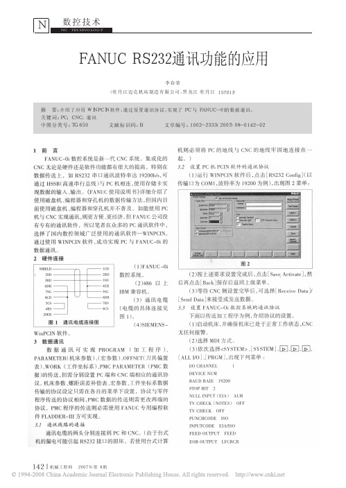
使用PCIN 软件实现PC 与FANUC-Oi的数据通讯, 根据现场使用的情况来看, 效果十分理想。
1 硬件配制(1)FANUC-0i 数控系统。
(2)486 以上IBM 兼容机。
(3) 通讯电缆( 电缆的具体连接见图1)。
(4)SIEMENS-PCIN 软件4.32 或以上版本。
图1 通讯电缆连接图2 数据通讯数据通讯可实现PROGRAM( 零件程序) 、PARAMETER( 机床参数) 、PITCH ( 螺距误差补偿表) 、MACRO( 宏参数) 、OFFSET( 刀具偏置表) 、WORK( 工件坐标系) 、PMC PARAMETER (PMC 数据) 的传送, 但需分别设置PC 端和CNC 端相应的通讯协议。
机床参数、螺距误差补偿表、宏参数、工件坐标系数据传输的协议设定只需在各自的菜单下设置, 协议与零件程序传送的协议相间,PMC 数据的传送则需更改两端的协议。
2.1 通讯线路的连接通讯电缆的两头分别连接到PC 和CNC 。
( 警告: 由于台式机的漏电可能引起RS232 接口的损坏, 若使用台式计算机则必须将PC 的地线与CNC 的地线牢固地连接在一起。
)2.2 设置PC 机PCIN 软件的通讯协议(1) 运行PCIN 软件后出现下列菜单:V24-INI DATA-IN DATA-OUT FIIE SPECIAL PC-FORMAT AR-CHIV-FIIE EXIT 。
(2) 使用左、右光标键, 选择V24-INI, 回车确认, 出现下列菜单:COM NUMBER 1( 根据PC 实际使用的通讯端口选择),BAUDRAIE 19200 ( 波特率),PARTIY EVEN ( 奇偶检验),2 STOP BITS( 停止位2 位),7 DA TA BITS( 数据位7位),X ON/OFF SET UP,END W-M30OFF ,TIME OUT 0S,BINFINE OFF ,TURBOMODE OFF,DON‘T CHECK DSR 。
rs232通信协议 使用版
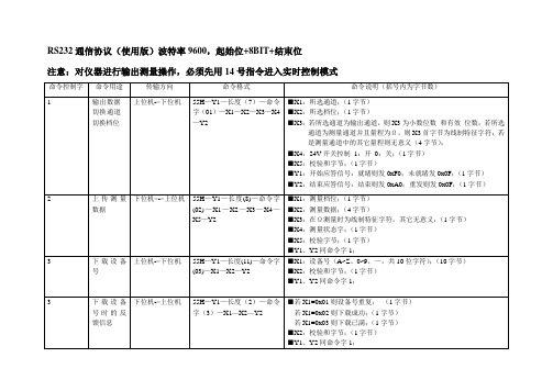
RS232通信协议(使用版)波特率9600,起始位+8BIT+结束位
注意:对仪器进行输出测量操作,必须先用14号指令进入实时控制模式
内部定义说明:
3)设备号字符定义
4)Ω测量线制定义
5)数据格式定义:
*X3低4位为小数位数;
当B0~3为0时,无小数位数及小数点;
当B0~3为1时,小数点后无有效数字但有小数点;
当B0~3为2时,小数点后一位有效数字,依此类推;
*X3中B5为符号位,为1时则数据为负数;
*有效数据中X2为最高8位,X0为最低8位;
6)输出状态标志定义
8)校验和定义
在通道中为了验证通讯是否正确,采用了校验和方式,将所有发送的数据(包括长度、命令字、数据信息)进行累加;通讯双方对各自的校验和进行比较,一致则为正确;否则需重发;
9)关于冷端温度设置的说明
当要模拟热电偶,需先设置好并下载冷端温度,然后才能发送热电偶型号信息;。
FANUC RS 通讯参数设置与操作

FANUC RS232通讯参数设置与操作Fanuc RS-232C Standard Serial PinoutFanuc ISO Protocol: (E,7,2,x)The standard protocol for Fanuc controls is 4800 or 9600 Baud, “Even parity”, “7 data bits” and2 stop bits” using DC1-4 Codes (XON/XOFF, PUNCH ON/OFF).Fanuc 0 M / TWith the Emergency Stop button depressed, set the PWE parameter on page 2 of the SETTINGS screen to a 1. Press DGNOS/PARAM, [PARAM] and page down to parameter 900. Enter the values for parameters 900-1000. At this time, set up the communication parameters again the same way you did in Part 1-CNC Parameter Settings. When you are finished, turn off the power to the control, then power on again.Punching ProcedurePunch NC Parameters - EDIT mode, PARAM screen, EOB + OUTPUT/STARTPunch PC Parameters - EDIT mode, DGNOS screen, OUTPUT/STARTPunch All Programs - EDIT mode, PRGRM screen, O-9999, OUTPUT/STARTTool Offsets - EDIT mode, OFFSET screen, OUTPUT/STARTReading ProcedureLoad NC Parameters - EDIT mode, PARAM screen, EOB + INPUTLoad PC Parameters - EDIT mode, DGNOS screen, INPUTLoad All Programs - EDIT mode, PRGRM screen, INPUTLoad Tool Offsets - EDIT mode, OFSET screen, INPUTClearing ProcedureDelete All memory - Power On holding RESET + DELETE keys with PWE=1Delete Parameters - Power On holding RESET key with PWE = 1Delete Programs - Power On holding DELETE key with PWE = 1Fanuc 0 DNC Drip-Feeding NoteMost machine tool builders enabled the ability for the CNC to run in drip feed mode (also called "Tape" mode,or "Auto" mode with a switch or keep relay set). You can determine if your machinesupports running files of any length in this mode that executed each line directly if you can make the "DNCI" bit in the Diagnostics area go to a "1". The "DNCI" bit is G127.5 (or Diagnostic bit 127= xx1x xxxx). If you have a switch, keep relay (found in the Diagnostic section by the way) then you are good to go. Put the machine in DNC mode, make sure you are in AUTO mode, get your PC ready to send the file and hit CYCLE START to start executing code. The code never goes into the part program memory, so code of any length can be run. Make sure you have a good DNC setup as any data loss (due to bad cabling or faulty flow control) can cause a crash.Fanuc 3M-CPUNCHINGPunch NC Parameters - EDIT mode, PARAMETER screen, P-9999, OUTPUT/STARTPitch Error Compensation - EDIT mode, PROGRAM screen, P-9998, OUTPUT/STARTPunch Programs - EDIT mode, PROGRAM screen, O-9999, OUTPUT/STARTPunch Tool Offsets - EDIT mode, OFFSET screen, P-9999, OUTPUT/STARTPunch Macro Variables - EDIT mode, Menu screen, P-9999, OUTPUT/STARTRECORD THE PMC PARAMETERSYou must manually copy down on paper ALL of the Diagnostic parameters off the DIAGNOSTIC screen.N600~619,N1001~1040,N2001~2010,N3000~3036.READINGLoad NC Parameters - Param enable, EDIT mode, PARAMETER screen, P-9999, INPUTPitch Error Compensation - EDIT mode, PROGRAM screen, P-9998, INPUTLoad Programs - EDIT mode, PROGRAM screen, O-9999, INPUTLoad Tool Offsets - EDIT mode, OFFSET screen, P-9999, INPUTLoad Macro Variables - EDIT mode, Macro screen, P-9999, INPUTRECORD THE SETTING DATAPress PARAMETERS key to display the Setting Data Screen. You can record all of the SettingN600~619,N1001~1040,N2001~2010,N3000~3036.OPERATION IN DNC MODEThis DNC software uses AUTO mode and runs the programs directly from a computer. Programsare not stored in the C-MOS Memory. Selecting between standard (C-MOS memory) or DNC mode of operation in the AUTO mode is done by setting the I/O=0 for MEMORY mode or 1 for DNC mode.·Go to MDI mode·Select the PARAMETER Setting screen·Set I/O = 1·Go to AUTO mode·Press RESET to clear memory buffers, then press the START button and the system will run the program being sent from the computer.·Using Spectrum Multi-DNC you can set it up to send the same program several times.·To get back to memory mode you must set I/O = 0 on the PARAMETER Setting screen.Fanuc 6/9PUNCHING:Punch NC Parameters - EDIT mode, PARAM screen, key “P-9999”, PunchPunch Pitch Error Compensation - EDIT mode, PARAM screen, key “P-9998”, PunchPunch All Programs - EDIT mode, PGRM screen, key “O-9999”, PunchTool Offsets - EDIT mode, OFSET screen, key “P-9999”, PunchPunch PC ParametersCheck Parameter 3, bit 7. If this is a 0, you have no PC Parameters. Write down the PC Parameters between, and including the following parameters: N600-619,N1001-1040, N2001-2010 and N3001-3036. READING:Load NC Parameters - EDIT, E-Stop, PWE, PARAM screen, key “P-9999”, ReadLoad Pitch Error Compensation - EDIT, E-Stop, PWE, PARAM screen, key “P-9998”, ReadLoad All Programs - EDIT mode, PGRM screen, Mem. Protect Key, key “O-9999”, Read Load PC ParametersCLEARING:Delete Directory and Programs - Power On holding “RESET” + “DELETE”Delete Entire BMU - PWE enabled, Power On holding “0”+”DELETE”Fanuc 10/11/12/15A/15B/15iBe sure to write down the NC (Service) parameters; 0, 3, 20-23, 5001-5122,9000 and 9100-9125/9131/9207 (depending on you control). Backup the Setting Screen Data, NC parameters, PC parameters(Timers,Counters, Keep Relays, Data Tables and Position Module Information) and Tool Offsets.PUNCHING:Punch NC Parameters - EDIT mode, SERVICE screen, key PUNCH - ALLPunch Pitch Error Compensation - EDIT mode, SERVICE screen, key PUNCH - PITCHPunch All Programs - EDIT mode, PRGRM screen, key PUNCH - ALLTool Offsets - EDIT mode, OFFSET screen, key PUNCH - TOOL READING:Load NC Parameters - EDIT, E-Stop, PWE, PARAM screen, key READ - ALLLoad Pitch Error Compensation - EDIT, E-Stop, PWE, PARAM screen, key READ - PITCHLoad All Programs - EDIT mode, PGRM screen, Mem. Protect Key, key READ - ALL CLEARING:Delete Directory and Programs - EDIT mode, PRGRM screen, key DELETE - PROGRAM – ALL Delete Entire BMU - PWE enabled, Power On holding “7” + “9”Fanuc 16/18/20/21-ABC i / 0iPunchingNC Parameters - EDIT mode; SYSTEM PARAM OPTR > PUNCH EXECPitch Error Compensation - EDIT mode; SYSTEM > PITCH OPTR > PUNCH EXECMacro Variables - EDIT mode; OFFSET > MACRO OPTR > PUNCH EXECAll Programs - EDIT mode; PRGRM > O – 9 9 9 9 PUNCH EXECOffsets - EDIT mode; OFFSET (or WORK ) OPTR > PUNCH EXEC ReadingNC Parameters EDIT mode, Protect key off; SYSTEM PARAM OPTR > READ EXEC Pitch Error Compensation EDIT mode; SYSTEM > PITCH OPTR > READ EXECAll Programs EDIT mode; #3202.4 & .0 = 0; PRGRM OPTR > READ EXEC Offsets EDIT mode; OFFSET (or WORK ), OPTR > READ EXECInitializingErase Entire Memory Power On holding O & RESET with Write Protect Key off Typical。
FANUC 0i BC 系统使用RS-232-C 接口的参数设定和电缆连接

FANUC 0i B/C系统使用RS-232-C接口的参数设定和电缆连接技术部:张锐由于经常有用户在使用RS-232-C接口时出现“086”、“087”报警,其主要原因就是参数没有设定好,或者电缆没有连接好。
下面就把标准参数及电缆管脚的连接介绍给大家(许多用户已使用过):一、参数设定二、电缆连接图NC(20P) 9P 9P 9P(PC)2 23 385146 注1:如果使用25芯插头将9芯的5脚改成25芯的7脚。
三、使用Windows 中的超级终端进行传输参数、加工程序1. 计算机侧的设定步骤1) Windows 98中的附件中的通信中选择超级终端,并执行。
该程序运行后则显示右图显示的画面2) 设定新建连接的名称CNC (或其他),并选择连接的图标。
设定方法如右图所示。
3) 在完成第2项的设定后,用鼠标确认确定按钮,则会出现右图所显示的画面,而后根据本计算机的资源情况设定进行连接的串口,本例子选择为直接连接到串口1。
4) 在完成第3项的设定后,用鼠标确认确定按钮,则会出现右图所显示的画面,该画面即为完成串行通信的必要参数。
波特率:9600(可根据系统设定的参数而定)数据位:8奇偶校验:无停止位:1流量控制:Xon/Xoff5) 完成第4项的设定后,进行设定该CNC连接的属性,在设置的画面中按右图所示的选择设定。
在以上的设定工作完成后,则可进行计算机与数控系统的通讯工作了,以下程序名称DEMO.txt 为例,进行通讯。
6) 在完成第5项的设定后,进行设定ASCII 码的设定画面,设定选择按右图所示的选择设定。
当要接收数控系统的信息时,首先要将计算机的CNC 连接打开,打开后从下拉菜单传送中选择捕获文本,并执行该程序,随即显示右图的显示内容,命名DEMO.TXT后,确认开始。
当要发送数控系统的信息时,首先要将数控系统处于接收状态,然后设定计算机的状态,从下拉菜单传送中选择发送文本文件,并执行该程序,随即显示右图的显示内容,选择DEMO.TXT 后,确认打开。
RS232控制命令方式

RS232控制命令方式一.通讯协议要求9600bps,8位数据位,1位停止位无校验无流控制;如果用户想把本机输入的第3路信号切换到第1路输出端子上时,(注意当前输入法是否为默认EN)用户可以键入S(或G)代表同步切换命令起始符, 01代表第一输出通道,< 代表切换,03代表输入通道此时,可以看到矩阵切换器动作,执行用户命令。
见右图:矩阵切换器执行用户命令完成后,在用户终端发送$>命令行起始符,准备再次接收用户命令。
二.命令格式VGA单独切换命令起始符为ASCII码的 G(十六进制的47) 或 g(十六进制的67 );同步切换命令起始符为ASCII码的 S (十六进制的53) 或 s (十六进制的73) ;AUDIO单独切换命令符A(十六进制的41)或a(十六进制的71)。
VIDEO单独切换命令符V(十六进制的56)或v(十六进制的76).:为两个数字ASCII码(01~02),表示命令所需控制的输出端口;(数字0~9的ASCII码值为十六进制的30~39)<:ASCII码值为十六进制的3C;:为两个数字ASCII码(01~24),表示命令所需控制的输入端口;:ASCII码回车符(十六进制的0D)。
例如:VGA单独切换时,把04路VGA输入信号切换到02路输出端口,该命令的十六进制;02路输入信号切换到01;控制器向矩阵切换器发送以上格式的十六进制格式命令,也同样可以完成上述操作。
三.关断输出操作命令ASCII码的 S (十六进制的53) 或 s (十六进制的73) ;VGA单独切换命令起始符为ASCII码的“ G”(十六进制的47) 或“g”(十六进制的67; AUDIO单独切换命令起始符为ASCII码的 A(十六进制的41) 或 a(十六进制的61);:为两个数字ASCII码,表示命令所要关断的输出端口;(数字0~9的ASCII码值为十六进制的30~39)О:ASCII码值为十六进制的4F,表示关断命令符;:为1个数字ASCII码(0或1),表示端口关断或打开;:ASCII码回车符(十六进制的0D)。
FANUCRS232通讯功能的应用
PARAMETER( 机床参数) 、( 宏参 数) 、OFFSET( 刀 具 偏 置 [ ALL I/O] 、[ PRGM] , 出现下列菜单 :
表) 、WORK( 工件坐标系) 、PMC PARAMETER ( PMC 数 据) 的传送, 但需分别设置 PC 端和 CNC 端相应的通讯协 议 。机 床 参 数 、螺 距 误 差 补 偿 表 、宏 参 数 、工 件 坐 标 系 数 据 传输的协议设定只需在各自的菜单下设置, 协议与零件 程序传送的协议相间, PMC 数据的 传 送 则 需 更 改 两 端 的 协议。PMC 程序的传送则必需使用 FANUC 专用编程软 件 FLADDER- III 方可实现。 3.1 通讯线路的连接
数据传 送 上 , 如 RS232 串 口 通 讯 波特 率 达 19200b/s, 可
( 1) 运行 WINPCIN 软 件 后 , 点 击[ RS232 Config]( 以
通过 HSSB( 高速串行总线) 与 PC 机相连, 使用存储 卡 实 传输口为 COM1, 波特率为 19200 为例) , 出现图 2 菜单:
CHANNEL DEVICE 1 DEVICE OTHERS FUNCTION READ ( 7) 选择[ EXEC] 。 ( 8) PC 机侧, 先选择要传送的路径及文件名, 然后选 择[ Send Data] 。PC 端会动态显示 PMC 参数传输过程直 至传送结束。
( 编辑 明 涛)
!!!!!!!!!! 作者简介: 李春荣( 1973- ) , 女, 工程师, 研究方向为数控机床。 收稿日期: 2007- 05- 15
通讯电缆的两头分别连接到 PC 和 CNC。( 由于台式
I/O CHANNEL
l
DEVICE NUM
FANUCRS232通讯参数设置与操作

FANUCRS232通讯参数设置与操作在FANUC机器人系统中,RS232通讯参数设置和操作如下:1.确认机器人支持RS232通讯:在FANUC机器人控制器的参数设置中,检查是否有RS232通讯相关参数。
2.连接机器人控制器和PC:使用RS232串口线缆,将机器人控制器的串口连接到PC的串口或USB转串口适配器。
3. 配置通讯参数:在机器人控制器中,进入RS232设置菜单,设置通讯波特率、数据位、停止位、校验位等通讯参数。
通常,波特率可设置为9600bps,数据位设置为8位,停止位设置为1位,校验位设置为无。
4.配置机器人控制器IP地址:在机器人控制器的网络设置中,配置控制器的IP地址。
确保PC和机器人控制器在同一网络中。
5. 配置PC端通讯软件:使用PC端的通讯软件,如HyperTerminal、PuTTY等,在软件中设置与机器人控制器相同的通讯参数,包括波特率、数据位、停止位等。
6.打开通讯软件并连接机器人:在PC端的通讯软件中,选择正确的串口并打开串口连接。
连接成功后,可以使用通讯软件发送和接收数据。
8.接收机器人控制器数据:在通讯软件中,可以接收机器人控制器返回的数据,如程序内容、机器人状态等。
9.断开通讯连接:在通讯完成后,关闭通讯软件,并断开PC与机器人控制器之间的串口连接。
需要注意的是,在进行RS232通讯时,需要确保串口连接正确、通讯参数一致,并且机器人控制器和PC在同一网络中。
另外,对于不同型号的FANUC机器人,RS232通讯参数和设置方法可能会略有不同,需要根据具体型号和用户手册进行操作。
总结起来,FANUCRS232通讯参数设置和操作步骤如下:确认机器人支持RS232通讯,连接机器人控制器和PC,配置通讯参数,配置机器人控制器IP地址,配置PC端通讯软件,打开通讯软件并连接机器人,发送数据到机器人控制器,接收机器人控制器数据,断开通讯连接。
通过以上步骤,可以实现FANUC机器人与PC之间的RS232通讯,实现数据传输和程序控制的功能。
- 1、下载文档前请自行甄别文档内容的完整性,平台不提供额外的编辑、内容补充、找答案等附加服务。
- 2、"仅部分预览"的文档,不可在线预览部分如存在完整性等问题,可反馈申请退款(可完整预览的文档不适用该条件!)。
- 3、如文档侵犯您的权益,请联系客服反馈,我们会尽快为您处理(人工客服工作时间:9:00-18:30)。
FANUC RS232通讯参数设置与操作Fanuc RS-232C Standard Serial PinoutFanuc ISO Protocol: (E,7,2,x)The standard protocol for Fanuc controls is 4800 or 9600 Baud, “Even parity”, “7 data bits” and2 stop bits” using DC1-4 Codes (XON/XOFF, PUNCH ON/OFF).Fanuc 0 M / TWith the Emergency Stop button depressed, set the PWE parameter on page 2 of the SETTINGS screen to a 1. Press DGNOS/PARAM, [PARAM] and page down to parameter 900. Enter the values for parameters 900-1000. At this time, set up the communication parameters again the same way you did in Part 1-CNC Parameter Settings. When you are finished, turn off the power to the control, then power on again.Punching ProcedurePunch NC Parameters - EDIT mode, PARAM screen, EOB + OUTPUT/STARTPunch PC Parameters - EDIT mode, DGNOS screen, OUTPUT/STARTPunch All Programs - EDIT mode, PRGRM screen, O-9999, OUTPUT/STARTTool Offsets - EDIT mode, OFFSET screen, OUTPUT/STARTReading ProcedureLoad NC Parameters - EDIT mode, PARAM screen, EOB + INPUTLoad PC Parameters - EDIT mode, DGNOS screen, INPUTLoad All Programs - EDIT mode, PRGRM screen, INPUTLoad Tool Offsets - EDIT mode, OFSET screen, INPUTClearing ProcedureDelete All memory - Power On holding RESET + DELETE keys with PWE=1Delete Parameters - Power On holding RESET key with PWE = 1Delete Programs - Power On holding DELETE key with PWE = 1Fanuc 0 DNC Drip-Feeding NoteMost machine tool builders enabled the ability for the CNC to run in drip feed mode (also called "Tape" mode,or "Auto" mode with a switch or keep relay set). You can determine if your machinesupports running files of any length in this mode that executed each line directly if you can make the "DNCI" bit in the Diagnostics area go to a "1". The "DNCI" bit is G127.5 (or Diagnostic bit 127= xx1x xxxx). If you have a switch, keep relay (found in the Diagnostic section by the way) then you are good to go. Put the machine in DNC mode, make sure you are in AUTO mode, get your PC ready to send the file and hit CYCLE START to start executing code. The code never goes into the part program memory, so code of any length can be run. Make sure you have a good DNC setup as any data loss (due to bad cabling or faulty flow control) can cause a crash.Fanuc 3M-CPUNCHINGPunch NC Parameters - EDIT mode, PARAMETER screen, P-9999, OUTPUT/STARTPitch Error Compensation - EDIT mode, PROGRAM screen, P-9998, OUTPUT/STARTPunch Programs - EDIT mode, PROGRAM screen, O-9999, OUTPUT/STARTPunch Tool Offsets - EDIT mode, OFFSET screen, P-9999, OUTPUT/STARTPunch Macro Variables - EDIT mode, Menu screen, P-9999, OUTPUT/STARTRECORD THE PMC PARAMETERSYou must manually copy down on paper ALL of the Diagnostic parameters off the DIAGNOSTIC screen.N600~619,N1001~1040,N2001~2010,N3000~3036.READINGLoad NC Parameters - Param enable, EDIT mode, PARAMETER screen, P-9999, INPUTPitch Error Compensation - EDIT mode, PROGRAM screen, P-9998, INPUTLoad Programs - EDIT mode, PROGRAM screen, O-9999, INPUTLoad Tool Offsets - EDIT mode, OFFSET screen, P-9999, INPUTLoad Macro Variables - EDIT mode, Macro screen, P-9999, INPUTRECORD THE SETTING DATAPress PARAMETERS key to display the Setting Data Screen. You can record all of the SettingN600~619,N1001~1040,N2001~2010,N3000~3036.OPERATION IN DNC MODEThis DNC software uses AUTO mode and runs the programs directly from a computer. Programsare not stored in the C-MOS Memory. Selecting between standard (C-MOS memory) or DNC mode of operation in the AUTO mode is done by setting the I/O=0 for MEMORY mode or 1 for DNC mode.·Go to MDI mode·Select the PARAMETER Setting screen·Set I/O = 1·Go to AUTO mode·Press RESET to clear memory buffers, then press the START button and the system will run the program being sent from the computer.·Using Spectrum Multi-DNC you can set it up to send the same program several times.·To get back to memory mode you must set I/O = 0 on the PARAMETER Setting screen.Fanuc 6/9PUNCHING:Punch NC Parameters - EDIT mode, PARAM screen, key “P-9999”, PunchPunch Pitch Error Compensation - EDIT mode, PARAM screen, key “P-9998”, PunchPunch All Programs - EDIT mode, PGRM screen, key “O-9999”, PunchTool Offsets - EDIT mode, OFSET screen, key “P-9999”, PunchPunch PC ParametersCheck Parameter 3, bit 7. If this is a 0, you have no PC Parameters. Write down the PC Parameters between, and including the following parameters: N600-619,N1001-1040, N2001-2010 and N3001-3036. READING:Load NC Parameters - EDIT, E-Stop, PWE, PARAM screen, key “P-9999”, ReadLoad Pitch Error Compensation - EDIT, E-Stop, PWE, PARAM screen, key “P-9998”, ReadLoad All Programs - EDIT mode, PGRM screen, Mem. Protect Key, key “O-9999”, Read Load PC ParametersCLEARING:Delete Directory and Programs - Power On holding “RESET” + “DELETE”Delete Entire BMU - PWE enabled, Power On holding “0”+”DELETE”Fanuc 10/11/12/15A/15B/15iBe sure to write down the NC (Service) parameters; 0, 3, 20-23, 5001-5122,9000 and 9100-9125/9131/9207 (depending on you control). Backup the Setting Screen Data, NC parameters, PC parameters(Timers,Counters, Keep Relays, Data Tables and Position Module Information) and Tool Offsets.PUNCHING:Punch NC Parameters - EDIT mode, SERVICE screen, key PUNCH - ALLPunch Pitch Error Compensation - EDIT mode, SERVICE screen, key PUNCH - PITCHPunch All Programs - EDIT mode, PRGRM screen, key PUNCH - ALLTool Offsets - EDIT mode, OFFSET screen, key PUNCH - TOOL READING:Load NC Parameters - EDIT, E-Stop, PWE, PARAM screen, key READ - ALLLoad Pitch Error Compensation - EDIT, E-Stop, PWE, PARAM screen, key READ - PITCHLoad All Programs - EDIT mode, PGRM screen, Mem. Protect Key, key READ - ALL CLEARING:Delete Directory and Programs - EDIT mode, PRGRM screen, key DELETE - PROGRAM – ALL Delete Entire BMU - PWE enabled, Power On holding “7” + “9”Fanuc 16/18/20/21-ABC i / 0iPunchingNC Parameters - EDIT mode; SYSTEM PARAM OPTR > PUNCH EXECPitch Error Compensation - EDIT mode; SYSTEM > PITCH OPTR > PUNCH EXECMacro Variables - EDIT mode; OFFSET > MACRO OPTR > PUNCH EXECAll Programs - EDIT mode; PRGRM > O – 9 9 9 9 PUNCH EXECOffsets - EDIT mode; OFFSET (or WORK ) OPTR > PUNCH EXEC ReadingNC Parameters EDIT mode, Protect key off; SYSTEM PARAM OPTR > READ EXEC Pitch Error Compensation EDIT mode; SYSTEM > PITCH OPTR > READ EXECAll Programs EDIT mode; #3202.4 & .0 = 0; PRGRM OPTR > READ EXEC Offsets EDIT mode; OFFSET (or WORK ), OPTR > READ EXECInitializingErase Entire Memory Power On holding O & RESET with Write Protect Key off Typical。