exlar内置压力传感器样本
传感器库存资料- 霍尼韦尔压力传感器型号霍尼韦尔压力传感器1.pdf
霍尼韦尔压力传感器型号霍尼韦尔压力传感器 142PC01D,142PC02D,142PC03D,142PC05D,142PC15D,142PC30D,142PC15A,142PC30A,142PC30G,141PC01D,141PC02D,141PC03D,141PC05D,141PC15D,141PC30D,143PC01D,143PC02D,143PC03D,143PC05D,143PC15D,143PC30D,141PC01G,141PC02G,141PC05G,142PC01G,142PC02G,142PC03G,142PC05G,142PC15G,163PC01D36,163PC01D48,163PC01D75,164PC01D76,163PC01D37,163PC01D76,161PC01D36,162PC01D36,164PC01D36,189PC15GM,189PC100GM,189PC150GM,ASCX01DN,ASCX05DN,ASCX15AN,ASCX15DN,ASCX30AN,ASCX30DN,ASCX100AN,ASCX100DN,ASCX150DN,ASCX150AN,ASDX015A24R,ASDX030A24R,ASDX100A24R,ASDX001G24R,ASDX005G24R,ASDX015G24R,ASDX020G24R,ASDX100G44R,ASDX001D44R,ASDX005D44R,ASDX015D44R,ASDX030D44R,ASDX100D44R,40PC001G2A, 40PC015G2A, 40PC100G2A, 40PC150G2A, 40PC250G2A, 40PC500G2A, 4040 PC001G2A, 4040PC015G2A, 4040PC100G2 A, 4040PC150G2A, 4040PC250G2A, 4040PC500G2A. 微压传感器 CPCL04DC,CPCL10DC,CPCL04DTC,CPCL10DTC,CPXL04DTC,CPXL10DTC,CPXL01DC,CPXL10DC,XPCL04DC,XPCL10DC,XPCL04DTC,XPCL10DTC,XPX50D,XPXL04DC,XPXL10DC,XPXL04DTC,XPXL10DTC,XSXL04D,XSXL10D,XSCL04DC,XSCL10DC,SDXL005D4,SDXL010D,SLP004D,SLP010D,DCXL01DN,DCXL05DN,DCXL10DN,DCXL20DN,DCXL30DN,DC001NDC4,DC002NDC4,DC005NDC4,DC010NDC4,DC020NDC4,DC030NDC4,DC001NDR4,DC002NDR4,DC005NDR4,DC010NDR4,DC020NDR4,DC030NDR4,DC001NDR5,DC002NDR5,DC005NDR5,DC010NDR5,DC020NDR5,DC030NDR5,DC2R5BDC4,DC005BDC4,DC075BDC4,DUXL01D,DUXL05D,DUXL10D,DUXL20D,DUXL30D。
西特setra model 205-2 压力传感器 说明书

Model 0 - -压力传感器▲适用于腐蚀性液体或气体▲表压和绝对压力PSI 量程西特 ( Setra ) Model 205-2 是专为精确测量与不锈钢相容的气体或液体压力而设计的压力传感器。
输出直流信号不需要另外附加信号与调节器,并且具有卓越的稳定性,高精度和快速动态响应等优良性能。
可靠的电路,以及西特专利的可变电容传感技术,使Model 205-2结构设计简洁。
一片17-4PH 不锈钢膜片和一个绝缘电极组成了一个可变电容,随着压力增加,电容减少。
Setra 独特的电路检测电容的变化并将其转换成直流信号。
压力范围注:Setra 坚持严格的质量标准ANSI-Z540-1。
此产品的标定源于NIST。
直流输出此设计保证了传感器在极限温度条件下具有低迟滞和可靠的稳定性。
Model 0 - 性能规范* 精度是非线性,迟滞和非重复性的RSS 值。
**这些性能参数是在70 0F 的温度条件下标定的,最大的温度误差通过这些数据计算。
* 工作温度的限制仅对电子元件而言, 压力介质温度可以更高或更低。
机械参数电气参数环境参数* 采用50K 的负载进行标定**零点输出,出厂设置在±50mV **满程输出,出厂设置在±50mV注意:在零压下,名义上输出导线的电压都高于激励电源负极1.6VDC。
激励负极或输出负极两者之一可以接到壳体(地),但是两个不能同时接到壳体。
出厂时以激励负极接壳体(地)为标定。
注意:氢气与17-4PH不锈钢不相容。
特选项订购指南例:订购Model 205-2, 25PSIA. 特选#710表示:25PSIA 绝对压力量程,精度为0.073%FS。
外形图底视图。
ASDX系列压力传感器说明书

ASDXRRX015PDAA 5ASDXAVX100PGAA5ASDXAVX100PGAA5ASDXAVX015PGAA5ASDXACX030PA7A5±DESCRIPTIONThe ASDX Series is a Silicon Pressure Sensor offering either an I 2C or SPI digital interface for reading pressure over the specified full scale pressure span and temperature range.The ASDX is fully calibrated and temperature compensated for sensor offset, sensitivity, temperature effects and non-linearity using an on-board Application Specific Integrated Circuit (ASIC). Calibrated output values for pressure are updated at approximately 1 kHz.The standard ASDX is calibrated over the temperature range of 0 °C to 85 °C [32 °F to 185 °F]. The sensor is characterized for operation from a single power supply of either 3.3 Vdc or 5.0 Vdc.These sensors are available to measure absolute, differential and gage pressures. The absolute versions have an internal vacuum reference and an output value proportional to absolute pressure. Differential versions allow application of pressure to either side of the sensing diaphragm. Gage versions are referenced to atmospheric pressure and provide an output proportional to pressure variations from atmosphere.The ASDX Series sensors are intended for use with non-corrosive, non-ionic working fluids such as air and dry gases. They are designed and manufactured according to standardsin ISO 9001.FEATURESOutput options: I 2C- or SPI-compatible 12-bit digitalPrecision ASIC conditioning and temperaturecompensated over 0 °C to 85 °C [32 °F to 185 °F]temperature rangeLow operating voltageAbsolute, differential and gage typesPressure ranges from 10 inches H 20 to 100 psiStandard calibrations in inches H 20, cm H 20, psi, mbar,bar, kPaTotal error band of ±2.0% of full scale span maximumRoHS compliantPOTENTIAL APPLICATIONSFlow calibratorsVentilation and air flow monitorsGas flow instrumentationSleep apnea monitoring and therapy equipmentBarometryPneumatic controls HVAC2/sensingTable 1. Absolute Maximum Ratings 1 ParameterMin Max Unit Supply voltage (V supply ) -0.3 6.0 Vdc Voltage to any pin-0.3 V supply + 0.3Vdc Digital clock frequency: I 2C SPI100 50 400 800 kHz ESD susceptibility (human body model) 3 - kV Storage temperature-50 [-58]125 [257] °C [°F] Lead temperature (2 s to 4 s)- 250 [482] °C [°F] External capacitance between V supply and ground 2 100 470nFTable 2. Operating Specifications ParameterMin. Typ. Max. Unit Supply voltage: (V supply )3 3.3 Vdc 5.0 VdcSensors are either 3.3 Vdc or 5.0 Vdc per the Order Guide (see Figure 1).3.04.75 3.345.04 3.6 5.25VdcSupply current2.03.5 5.0 mA Compensated temperature range 5 0 [32] - 85 [185] °C [°F] Operating temperature range 6 -20 [-4]- 105 [221] °C [°F]Overpressure 7 2X operating pressure range minimum Burst pressure 83X operating pressure range minimumStartup time (power up to data ready) - 2.8 7.3 ms Response time- 0.46 - ms I 2C or SPI voltage level low - - 0.2 V supply I 2C or SPI voltage level high0.8 - - V supply Pull-up on SDA and SCL (I 2C output only) 1 - - kOhm Total error band 9 - - 2.0 %FSS 10 Output resolution12- - bitsTable 3. Environmental Specifications Parameter Characteristic Humidity 0% to 95% RH non-condensing Vibration 10 G at 20 Hz to 2000 Hz Shock 100 G for 11 ms Life 1 million cycles minimum Table 4. Wetted Materials 11 Parameter Port 1 (Pressure Port)12 Port 2 (Reference Port)12 Covers glass-filled PBT glass-filled PBT Adhesives silicone silicone and epoxy Electronic components silicon and glass silicon, glass, and goldNotes:1. Absolute maximum ratings are the extreme limits that the device will withstand without damage to the device.2. An external bypass capacitor is required across the supply voltage (Pins 6 and 3 – see Figure 4) as close to the sensor supply pin as possiblefor correct sensor operation.3. Ratiometricity of the sensor (the ability of the output to scale to the input voltage) is achieved within the specified operating voltage for eachoption. Other custom supply voltages are available, please contact Honeywell Customer Service.4. The sensor is not reverse polarity protected. Incorrect application of excitation voltage or ground to the wrong pin may cause electrical failure.5. The compensated temperature range is the temperature range (or ranges) over which the sensor will produce an output proportional topressure within the specified performance limits.6. The operating temperature range is the temperature range over which the sensor will produce an output proportional to pressure but may notremain within the specified performance limits.7. Overpressure is the maximum pressure which may safely be applied to the product for it to remain in specification once pressure is returned tothe operating pressure range. Exposure to higher pressures may cause permanent damage to the product.8. Burst pressure is the maximum pressure that may be applied to any port of the product without causing escape of pressure media. Productshould not be expected to function after exposure to any pressure beyond the burst pressure.9. Total error band is the maximum deviation in output from ideal transfer function over the entire compensated temperature and pressure range.Includes all errors due to offset, full scale span, pressure non-linearity, pressure hysteresis, repeatability, thermal effect on offset, thermal effect on span and thermal hysteresis. Specification units are in percent of full scale span (%FSS).10. Full scale span (FSS) is the algebraic difference between the output signal measured at the maximum (Pmax.) and minimum (Pmin.) limits ofthe pressure range.11. Consult Honeywell Customer Service for detailed material information.12. For AC pressure p ort configuration, the “pressure” and “reference” ports are reversed.Honeywell Sensing and Control3Figure 1. Nomenclature and Order GuideASDX_ __ _ _ _ _ __Power Supply Voltage3 = 3.3 Vdc 5 = 5.0 VdcPackage Selection13Calibration SelectionSeriesGage -010NG = 10 in H 2O-025CG = 25 cm H 2O 001PG = 1 psi 005PG = 5 psi 015PG = 15 psi 030PG = 30 psi 100PG = 100 psi -025MG = 25 mbar 050MG = 50 mbar 100MG = 100 mbar 200MG = 200 mbar 500MG = 500 mbar 001BG = 1 bar 002BG = 2 bar 007BG = 7 bar 003KG = 3 kPa 004KG = 4 kPa 005KG = 5 kPa 010KG = 10 kPa 020KG = 20 kPa 050KG = 50 kPa 100KG = 100 kPa 200KG = 200 kPa 700KG = 700 kPaDifferential 005ND = ±5 in H 2O 010ND = ±10 in H 2O 015CD = ±15 cm H 2O 025CD = ±25 cm H 2O 001PD = ±1 psi 005PD = ±5 psi 015PD = ±15 psi 030PD = ±30 psi -015MD = ±15 mbar 025MD = ±25 mbar 050MD = ±50 mbar 100MD = ±100 mbar 200MD = ±200 mbar 500MD = ±500 mbar 001BD = ±1 bar 002BD = ±2 bar -003KD = ±3 kPa 004KD = ±4 kPa 005KD = ±5 kPa 010KD = ±10 kPa 020KD = ±20 kPa 050KD = ±50 kPa 100KD = ±100 kPa 200KD = ±200 kPa - Absolute - -- - --015PA = 15 psi 030PA = 30 psi 100PA = 100 psi ------001BA = 1 bar 002BA = 2 bar 007BA = 7 bar ------100KA = 100 kPa 200KA = 200 kPa 700KA = 700 kPaPressure Range 16, 17, 18Transfer Function Limits 14A = 10% to 90% calibrationB = 5% to 95% calibrationOutput Type 15S = SPI2 = I 2C, Address 0x283 = I 2C, Address 0x384 = I 2C, Address 0x485 = I 2C, Address 0x586 = I 2C, Address 0x687 = I 2C, Address 0x78_Pressure PortAV = Axial port on top, vented cover on bottomRR = Radial port on top, radial port on bottomAC = Axial port, sealed cover (commonly used for absolute)RV = Radial port, singleFuture OptionX13. Other package combinations are possible, please contact Honeywell Customer Service.14. The transfer function limits define the output of the sensor at a given pressure input. By specifying the output signal at the maximum (Pmax.)and minimum (Pmin.) limits of the pressure range, the complete transfer curve for the sensor is defined. See Figure 2 for a graphicalrepresentation of each calibration. For the 12-bit digital output, Table 6 provides the output of the sensor at significant percentages. These outputs are valid at the rated input voltage of the sensor.15. The output type defines which communication protocol the sensor uses to communicate. Available protocols are I 2C or half duplex SPI (sensoracts only as a slave). This communication protocol is not field selectable, and must be defined when ordering the sensor. 16. Custom pressure ranges are available, please contact Honeywell Customer Service.17. The pressure units (inches H 20, cm H 20, psi, mbar, bar, kPa) define the units used during calibration and in the application. 18. See Table 5 for an explanation of sensor types.4 /sensingTable 5. Sensor Types Type DescriptionAbsoluteOutput is proportional to difference between applied pressure and built-in reference to vacuum (zero pressure). GageOutput is proportional to difference between applied pressure and atmospheric (ambient) pressure.DifferentialOutput is proportional to difference between pressure applied to each of the pressure ports (Port 1 – Port 2).Figure 2. Transfer Functions and Limits A Calibration, 10% to 90%B Calibration, 5% to 95%Table 6. Sensor Output at Significant Percentages% Output Digital Counts (dec)Digital Counts (hex)0% 0 0x0000 5% 819 0x0333 10% 1638 0x0666 50% 8192 0x2000 90% 14746 0x399A 95% 15565 0x3CCD 100% 16383 0x3FFFFigure 3. Completed Catalog Listing Example ASDXAVX001PG2A3: AV pressure port, 1 psi gage, I 2C output (Address 0x28), 10% to 90% calibration at 3.3 Vdc operation.ASDXAVX001PG2A3 Output vs PressureHoneywell Sensing and Control5Figure 4. Dimensional Drawings (For reference only: mm [in].)AV Package (Legacy G2)RR Package (Legacy D4) AC Package (Legacy A2)RV PackageTable 7. PinoutI 2C SPI Pin Definition Type DescriptionPin Definition Type Description1 SDA digital I/O serial bidirectional data; data is clocked in or out on clock edge of SCL1 MISO digital output “Master In Slave Out” - serial output data; data is clocked out on clock edge of SCK2 SCL digital input serial clock input; used to clock data on SDA 2 SCK digital input serial clock input; used to clock data on MISO3 GND supply power supply ground 3 GND supply power supply ground4 N/C not used do not connect in the application4 N/C not used do not connect in the application5 SS digital output interrupt signal (conversion complete output) 5 SS digital input slave select6 Vsupply supply power supply source 6 Vsupply supply power supply source7 N/C not used do not connect in the application7 N/C not used do not connect in the application8N/Cnot useddo not connect in the application8N/Cnot useddo not connect in the applicationSensing and Control Honeywell1985 Douglas Drive NorthGolden Valley, MN 55422 /sensing 008095-11-EN IL50 GLO Printed in USAJuly 2010Copyright © 2010 Honeywell International Inc. All rights reserved.WARNINGWARRANTY/REMEDYHoneywell warrants goods of its manufacture as being free of defective materials and faulty workmanship. Honeywell’s standard product warranty applies unless agreed to otherwise by Honeywell in writing; please refer to your order acknowledgement or consult your local sales office for specific warranty details. If warranted goods are returned to Honeywell during the period of coverage, Honeywell will repair or replace, at its option, without charge those items it finds defective. The foregoing is buyer’s sole r emedy and is in lieu of all other warranties, expressed or implied, including those of merchantability and fitness for a particular purpose. In no event shall Honeywell be liable for consequential, special, or indirect damages.While we provide application assistance personally, through our literature and the Honeywell web site, it is up to the customer to determine the suitability of the product in the application.Specifications may change without notice. The information we supply is believed to be accurate and reliable as of this printing. However, we assume no responsibility for its use.WARNINGMISUSE OF DOCUMENTATIONThe information presented in this product sheet is forreference only. Do not use this document as a productinstallation guide.Complete installation, operation, and maintenanceinformation is provided in the instructions supplied witheach product.Failure to comply with these instructions could result in death or serious injury.SALES AND SERVICEHoneywell serves its customers through a worldwide network of sales offices, representatives and distributors. For application assistance, current specifications, pricing or name of the nearest Authorized Distributor, contact your local sales office or:E-mail:*********************Internet: /sensingPhone and Fax:Asia Pacific +65 6355-2828; +65 6445-3033 FaxEurope +44 (0) 1698 481481; +44 (0) 1698 481676 Fax Latin America +1-305-805-8188; +1-305-883-8257 FaxUSA/Canada +1-800-537-6945; +1-815-235-6847+1-815-235-6545 FaxASDXACX100PAAA 5ASDXAVX015PG7A5ASDXAVX030PGAA5ASDXRRX005NDAA5ASDXRRX015PDAA5ASDXRRX015PGAA 5ASDXRRX030PDAA5ASDXRRX030PGAA5ASDXRRX100PD2A5ASDXRRX100PGAA5ASDXRRX015PDAA 5ASDXAVX100PGAA5ASDXAVX100PGAA5ASDXAVX015PGAA5ASDXACX030PA7A5。
GEFRAN压力传感器下载资料

个人资料整理,仅供个人学习使用GEFRAN压力传感器下载资料TK-E-1-E-B05C-H-VTK-E-1-F-M02U-M-V(2Mpa)压力传感器TK-E-1-F-M05D-M-V(50Mpa)压力传感器TK-E-1-F-M05U-M-V(5Mpa)压力传感器TK-E-1-F-MV50-M-V(0.5Mpa)压力传感TK-E-1-F-M01U-M-V(1Mpa)压力传感器TK-E-1-F-M02D-M-V(20Mpa)压力传感器TK-E-1-F-P15C-H-VTK-E-1-F-P03M-H-VTK-E-1-F-P05M-H-VTK-E-1-F-P75C-H-VTK-E-1-F-P25C-H-VTK-E-1-E-B01D-H-VTK-E-1-E-B16U-H-VTK-E-1-E-B03D-H-VTK-E-1-E-B04D-H-VTK-E-1-E-B05D-H-VTK-E-1-E-B06D-H-VTK-E-1-E-B01C-H-VTK-E-1-E-B16D-H-VTK-E-1-E-B02C-H-VTK-E-1-E-B25D-H-V以下品牌具有强大优势:一、气动元件:电磁阀气缸德国品牌:德国FESTO费斯托气动元件,德国宝德BURKERT电磁阀,英国海隆诺冠日本品牌:日本SMC气动元件,日本CKD喜开理气动元件...意大利品牌:意大利UNIVER,意大利康茂盛美国品牌:美国ROSS,美国ASCO电磁阀,美国MAC电磁阀台湾:台湾MINDMAN金器,台湾AIRTAC亚德客二、工控产品传感器、继电器、变频器、开关德国品牌:德国PILZ皮尔兹继电器,德国IFM易福门传感器,德国海德汉HEIDENHAIN,德国P+F倍加福传感器,德国RENCON编码器,德国施克SICK,德国TURCK图尔克,德国HIRSCHMANN赫斯曼工业交换机。
德国亨士乐,德国MURR穆尔,德国金钟默勒日本品牌:日本神视SUNX...美国品牌:巴士德BARKSDALE三、液压元件液压泵{柱塞泵、齿轮泵叶片泵}液压阀{换向阀、溢流阀等等}美国品牌:美国NUMA TICS纽曼蒂克,美国PARKER派克气动液压,美国VICKERS威格士,美MOOG穆格,美国FAIRCHILD,美国POSEMOUNT罗斯蒙特,美国艾默生EMERSON,美国哈希HACH,美国丹尼逊液压元件,美国克力帕德国品牌:德国HAWE哈威,德国REXROTH力士乐,德国HYDAC贺德克,德国E+H,德国博力士乐...1 / 1。
压力传感器SA-1001-002规格书说明书
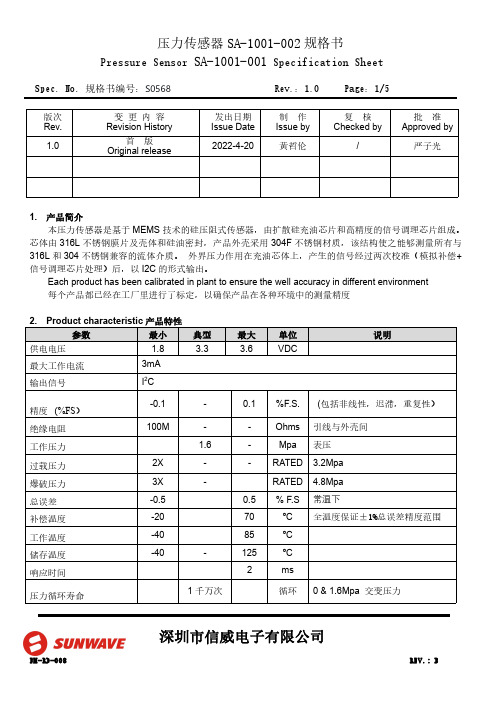
Spec.No.规格书编号:S0568Rev.:1.0Page:1/5深圳市信威电子有限公司版次Rev.变更内容Revision History发出日期Issue Date 制作Issue by 复核Checked by批准Approved by 1.0首版Original release2022-4-20黄哲伦/严子光1.产品简介本压力传感器是基于MEMS 技术的硅压阻式传感器,由扩散硅充油芯片和高精度的信号调理芯片组成。
芯体由316L 不锈钢膜片及壳体和硅油密封,产品外壳采用304F 不锈钢材质,该结构使之能够测量所有与316L 和304不锈钢兼容的流体介质。
外界压力作用在充油芯体上,产生的信号经过两次校准(模拟补偿+信号调理芯片处理)后,以I2C 的形式输出。
Each product has been calibrated in plant to ensure the well accuracy in different environment 每个产品都已经在工厂里进行了标定,以确保产品在各种环境中的测量精度Spec.No.规格书编号:S0568Rev.:1.0Page:2/5深圳市信威电子有限公司3.输出接口及管脚定义注:1.产品的内部电路已经在I2C 总线上放置了4.7K 的上拉电阻2.所有管脚与产品的金属外壳之间是绝缘的4.产品外形结构(单位:mm )5.功能描述5.1.工作模式传感器的默认工作模式为:产品上电后,进入到休眠状态,仅在接收到相应的I2C 命令后才会启动一次压力和温度的测量动作,之后再次自动进入休眠状态,以节省功耗。
5.2.上电启动及休眠唤醒当电源电压小于0.2V 时,传感器处于复位状态,在电源电压以最低10V/ms 的上升速率经过1ms 的延迟后,I2C 接口处于正常状态,可以接受主机命令,在经过2.5ms 的延迟后,传感器可以进行正常的压力和温度测量。
当传感器处于休眠状态时,在接收到主机命令后的0.5ms 时间内从休眠状态进入到工作模式,详细请参Spec.No.规格书编号:S0568Rev.:1.0Page:3/5深圳市信威电子有限公司照上电时序图6.I2C 接口6.1.I2C 接口电气特性在产品内部,I2C 总线的时钟信号线和数据线已经具有4.7k 的上拉电阻6.2.I2C 通讯速率本传感器的I2C 接口可工作于标准模式(100Kbit/s )、快速模式(400Kbit/s)、和高速模式(3.4Mbit/s)。
海尔 PX700 压力传感器电压输出型号说明书

350 DP41-E, DP25B-E, DP460-E
MODEL NO. CH-4620
PRICE DESCRIPTION
$95 Reference Book: Rotordynamics Prediction in Engineering
Comes with complete operator’s manual.
81 (3.19)
67 (2.63)
56 (2.19)
34 (1.31)
64 (2.5)
37 (1.44)
B
Enclosure
31 (1.19)
SPECIFICATIONS
4 to 20 mA Output Excitation: 12 to 32 Vdc unregulated
Output: 4 to 20 mA
2000 to 10,000 psi
A Dimension
127 (5.00)
160 (6.28)
24 (0.9375)
PRESSURE PORT
Dimensions: mm (in)
Typical Life: 100 million cycles
Operating Temperature: -18 to 71°C (0 to 160°F)
350 DP41-E, DP25B-E, DP460-E 350 DP41-E, DP25B-E, DP460-E 350 DP41-E, DP25B-E, DP460-E 350 DP41-E, DP25B-E, DP460-E
Weight: 672 g (23.7 oz) to 1000 psi 686 g (24.2 oz) from 2000 psi
EX-V系列涡电流位移传感器

498EX-V 系列高速高精度数字涡电流位移传感器特性●高精度涡电流传感器●解析度为 F.S. 的 0.02%●线性度为 F.S. 的 ± 0.3%●25 µs 的超高速取样 ●多种测量模式测量距离圆柱型 – 0 至 1 mm 螺纹型 – 0 至 2 mm 圆柱型/螺纹型 – 0 至 5 mm0 至 10 mm细长型 – 0 至 4 mm同级产品中最佳的精确度及高速取样系列结合了高速取样及新开发的线性修正电路,使它较传统的过电流系统有大幅的性能改良。
高速取样:每秒取样 40,000 次的 0.02%,线性度:F.S. 的 ±0.3%快速操作的基本模式测量周期输出公差极限值存储功能存储器最多可储存 4 个上/下限公差设定,您可以利用外部信号来切换这些设定,这让生产线转换更加快速且容易。
比较器输出取消的输入比较器输出可以利用外部信号予以停止,在连续的比较器操作时,您可以停止输出直到装置稳定操作为止。
选取模式ø5.4 mm t =4.8 mm18 mm高速高精度数字涡电流位移传感器测得的波形测得的波形测量精密电动机的细微振动区分轴承的外径检测齿轮的偏心率测量滚轴之间的间隙高速高精度数字涡电流位移传感器数字控制器上的按钮来设定计时器的作用及平均值的计算。
,同步化也不需要使用外部装置。
以 FLL 电路达到高精度FLL(平整线性化)电路会对每个个别的感测头进行最佳的线性化修正,您可以通过简单的设定就能以同级产品中最佳的精确度进行测量。
高速数字处理电路可以精确的检测传统取样速度所无法检下死中点模式自动检测行程的下死中点。
检测超声波熔接装置的下死中点EX-V 系列可以测量超声波熔接装置的角型头的下死中点,以检测熔接缺陷。
KEYENCE 的传统机型EX-V: 40,000/sEX-V解析度:F.S. 的 0.04%解析度:F.S. 的 0.02%理想线高解析度:F.S.的0.02% 线性度:F.S. 的±0.3%理想线高速高精度数字涡电流位移传感器测量轴的偏心率可以测量快速转动的轴的偏心率以检测是否有异常。
PX14x系列压力传感器产品说明书

Compatible MeterS* DP41-E, DP25B-E, DP24-E DP41-E, DP25B-E, DP24-E DP41-E, DP25B-E, DP24-E DP41-E, DP25B-E, DP24-E DP41-E, DP25B-E, DP24-E DP41-E, DP25B-E, DP24-E DP41-E, DP25B-E, DP24-E DP41-E, DP25B-E, DP24-E DP41-E, DP25B-E, DP24-E DP41-E, DP25B-E, DP24-E DP41-E, DP25B-E, DP24-E DP41-E, DP25B-E, DP24-E DP41-E, DP25B-E, DP24-E DP41-E, DP25B-E, DP24-E
Comes complete with operator’s manual.
* Visit us online for compatible meters.
Ordering Examples: PX142-015D5V, 0 to 15 psi differential pressure.
PX141-005V5V, -5 psi to 0 vacuum range.
U High-Impact Plastic Case
U Accurate
U All Models Temperature Compensated
SPECIFICATIONS
Excitation: 8 Vdc regulated (7 to 16 limits) @ 8 mA Output: 1 to 6 Vdc (±2.5 Vdc PX143) Linearity: ±0.75% FS BFSL (±1.5% FS PX143) Hysteresis: 0.15% FS (0.30% FS ≤5 psi range) Zero Balance: 1.0 Vdc ±0.05 (3.50 Vdc ±0.05 PX143)
- 1、下载文档前请自行甄别文档内容的完整性,平台不提供额外的编辑、内容补充、找答案等附加服务。
- 2、"仅部分预览"的文档,不可在线预览部分如存在完整性等问题,可反馈申请退款(可完整预览的文档不适用该条件!)。
- 3、如文档侵犯您的权益,请联系客服反馈,我们会尽快为您处理(人工客服工作时间:9:00-18:30)。
Force Measuring OptionExlar GSX and I Series ActuatorsGSX SeriesLinear Actuator• Measuring of compressiveloads with optional bi-directional load measurement• Integrated strain gauge loadcell• 10 VDC external excitation• 2 mV/V sensitivity• +/- 1% linearity• +/- 0.5% repeatability• Hysteresis, 1% nominal• 250 Hz frequency response• Factory calibrated• Compatible with standardgauge monitors and PLCstrain gauge input cards• Requires external excitation• Totally enclosed within theactuator’s sealed housing, andconnectorized for ease of use Force MeasuringActuatorsExlar offers select models ofits GSX and I Series actuatorswith integral force measuringcapability. This option is avail-able in the GSX30, 40, 50 &60 models and the I30 and 40models.In both product lines a load cellis embedded within the actua-tor allowing it to directly mea-sure the force being applied bythe actuator’s output rod. Thestrain gauge load sensor usedto measure applied force ismounted inside the actuator’scase, protecting it from exter-nal damage and guaranteeingaccurate and consistent forcedata.A separate connector is sup-plied for connecting the internalload cell to an external strainconditioner/amplifi er required toexcite the strain gauge sen-sor. Alternatively, Exlar canoffer strain gauge conditionersto provide a high level outputsignal, either 0-10V or 4-20mA.Alternatively, any one of nu-merous conditioners/amplifi ersavailable can be used for thispurpose.FeaturesApplications• Fastening and Joining• Riveting• Bag Sealing• Thermoforming• Welding• Fillers• Formers• Clamping• Molding• Precision Grinders• Precision Pressing• Interference Detection• Die Cutters• Injection Molding• Tube Bending• Stamping• Test Stand Lifts• Tension Control• Wire Winding• Parts Clamping• Dispensers• Circuit Board Testing• Blood ProcessingStrain Gauge AmplifierI SeriesLinear ActuatorAchievingPreciseMeasurementFrequently industrial applica-tions involving linear actuationrequire the precise measure-ment of the load being appliedby the actuator. Historicallythese have been accomplishedby placing a load cell betweenthe actuator and the connec-tion to the workpiece.This approach provides sev-eral challenges. Load cellsneed to be sized, selected andordered. Mechanical linkagesand mountings need to bedesigned, built and assembled.Precise alignment must bemaintained to prevent bendingmoments which can severelydegrade the accuracy of anyload measurement systeminvolving load cells.Provisions for securing thewires to the load cell needto be designed particularly ifthe load cell is moving in theprocess of applying the force.Moving wires are extremelyprone to failure and consid-eration must be given to theamount of fl exing. Lastly, a2the actuator. Over-load capac-ity of a minimum of 2x rating is provided to reduce the possibility of inadvertent load damage due on occasions when higher than planned high peak forces are applied.Confi gurationThe standard confi gurations of-fer measurement of compressive loads. Optional confi gurations are available to offer bi-direction-al measurement of force.Load cell amplifi ers commonly used with load cells contain power, excitation, and signal conditioning. These modules will amplify the output signal from milli-volts to useable levels of0-10V or 4-20mA. These devices are available as stand-alone devices made for mount-ing in an electrical panel, incor-porated into panel meters with digital displays, or integral to a PLC or other control device. Exlar’s force measuring actuator assemblies are factory calibrated and certifi ed providing you the information needed to quickly and simply set up your measur-ing system.strain gauge signal conditioner must be selected, ordered, in-stalled and calibrated.What seems on the front end to be a simple implementation ofa force measuring system fre-quently turns into a project requir-ing expertise from both electrical and mechanical personnel. It is also common to see such projects extend beyond the target comple-tion date as system components are redesigned or reordered. Exlar’s embedded force measur-ing option eliminates much ofthe effort and the risk associated with measuring the applied force produced by the actuator. This system will deliver specifi ed per-formance and allow you to meet target dates as all design work is fi eld-proven and factory-tested by Exlar.Flexing cables are not neces-sary. The actuator body typically does not move as it applies force. The force signal cable can be run alongside the actuator’s central and power cables. And, the force sensor carries the same IP rating of the actuator since it is located inside the actuator’s case. Typically the load cell’s rating ismatched to full load capacity of3*This is the frequency response of a “locked rotor” load cell actuator.Frequency response of the load cell/actuator system will depend on total system inertia and the motor and drive ampli fi er powering the system.*Tension optionalForce Measuring GSX & I Series ActuatorsGSX Actuator with Compression Force Measurement, Optional Bi-directional MeasurementLoad CellGSX Actuator with Clevis Mount andCompression Only Force MeasurementLoad CellI Series Actuator with Compression Force MeasurementLoad Cell*Reduced from standard actuator rodStrain Gauge Ampli fi ersAll Exlar precision load mea-suring designs are incremental in nature. By this it is intended that force measurements always be conducted as the change in the signal output between the start of each load producing motion and its completion. The force measur-ing option is not intended to be used as an absolute measure-ment of force being applied.Exlar can provide strain gauge ampli fi ers that offer a conve-nient method for accurately and reliably measuring the resistance change per cycle of the strain gauge load cell embedded in either a GSX or I Series actuator.These units convert the small mV changes in load cell output to a 0-10 volt or 4-20 mA sig-nal which is proportional to the load or tension being applied by the actuator. These ampli-fi ers can be DIN rail or panel mountable, with or without displays.Typical Features • DIN rail panel • 24 Volt power• +/- Volt or 0/4-20 mA output • Simple gain & offset adjust- ments• Auto calibration • Simple fi ltering options • With or without displayStrain Gauge Function • The strain gauge acts as a resistor in one leg of a Wheat-stone bridge• The strain gauge ampli fi er ap-plies voltage across the bridge at A-A (excitation voltage), causing current to fl ow through the bridge • The resistance of the strain gauge changes as a function of the force being applied• The output voltage across B-B changes as a function of the force being applied to the load cell.Model GSX40 Actuator with Load Cell Serial No 6090825TypeCompression Load Cell Calibration Factor2.1809 mV/V Full Scale Calibration Full Scale Load 20,000 Pounds Excitation Voltage +/-10V Linearity <1%Max Load4000 PoundsSee Operation Manual for wiring and operation instructionsExample Calibration and Load Informationinput voltage (+/- 10 Vdc usually)ABB AOutput Voltage (V)Typical System Wiring DiagramLoad CellTypical Strain Gauge Ampli fi erExlar Corporation1470 Lake Drive West Chanhassen, MN 55317 Tel: 952-368-3434Fax: 952-368-4877。