YS-V0.7一体化语音识别模块使用手册
YT07语音模块说明书
设备ID为本语音模块设备编码,通过录音软件设定。取值范围0-255。
485网络中有多个语音模块,通过设备ID区别模块。
5.
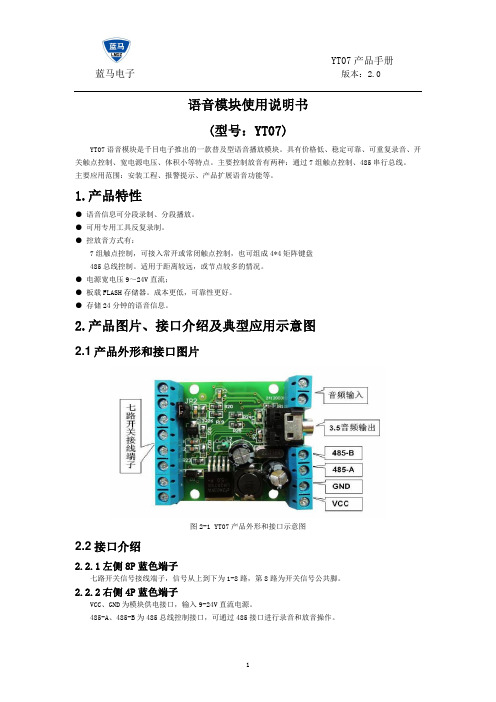
工作电源电压:直流9~24V
最大电流:150MA
工作温度:-20~85℃
音频输出功率:8欧3W 4欧3W
6.常见问题和注意事项
4
指示灯待命时闪动,触发后也没有反应,仍然闪动。
1、设置的控制方式不对。
2、只有第一段声音有效:公共端是8号端子,可能是误把1号端子当成公共端了。
5
指示灯待命时闪动,触发后有一段时间常亮,但是没有一点声音。
1、调整蓝色可调电阻音量。逆时针音量增大。
2、喇叭未接好,需要连接8欧喇叭,接在指定的端子上。
图4-3:闭合播放一次
4.1.2
单个控制触点与公共触点保持闭合时,播放语音。播完一遍之后,检测触点如果仍然保持闭合,则继续播放。如果多个触点符合条件,只检测较靠前的触点。
图4-4:闭合循环播放
4.1.3
单个控制触点与公共触点由闭合跳变断开时,只触发一次播放。如果始终保持断开,不再触发播放。
图4-5:断开播放一次
2、模块录音过程中不能进行放音操作,电脑软件不要进行其他操作。只等录音完成。
3、放音时,手碰到电路上引起干扰,手移开杂音就可以消失。
4、有交流声杂音,电源绞波太大,更换电源或并联加大电容滤波。
语音模块使用说明书
(型号:YT07)
YT07语音模块是千目电子推出的一款普及型语音播放模块。具有价格低、稳定可靠、可重复录音、开关触点控制、宽电源电压、体积小等特点。主要控制放音有两种:通过7组触点控制、485串行总线。
YS-LDV7语音识别模块使用手册

飞音云电子技术支持:751956552@ 网络销售:乐声001(阿里旺旺ID)LDV7语音识别模块使用手册目录1、初次使用测试步骤 (3)2、配套程序识别命令修改步骤 (4)(1)添加关键词和识别码 (4)(2)定义识别码 (5)(3)修改处理函数 (5)3、与单片机设备串口通讯 (7)4、程序下载说明 (8)5、灵敏度(识别距离)调节说明 (8)5、其他说明 (9)6、注意事项 (9)飞音云电子技术支持:751956552@网络销售:乐声001(阿里旺旺ID)1、初次使用测试步骤(1)按照图1所示,连接USB下载器,接上GND、RXD、TXD、5V,注意RXD/TXD必须交叉连接,才能进行一收一发通信,在PC机上打开串口调试工具,设定波特率为Array 9600bit/s。
(2)将USB下载器连接到PC机,查看该下载器在PC机中占用的串口通道,然后对应选择调试工具的串口号,设定后,重新给模块通上电源(拔下GND连接线,再重新连接,(图1)即可以重新上电,下载程序时冷启动也是一样的操作),这时,调试工具接收窗口将打印出相关口令。
(3)本模块出厂默认下载的是口令模式程序,用户根据串口所示的口令内容,先对着咪头发一级口令(“小杰”),待板上的D1灯点亮后,可以开始对其他二级口令的识别,如此循环操作识别。
识别操作。
如识别成功,则有相关反馈信息。
(4)调试完毕(5)测试好模块后可以与其他单片机设备进行通讯,连接方式和测试方法与在PC机调试一样。
飞音云电子技术支持:751956552@网络销售:乐声001(阿里旺旺ID)飞音云电子技术支持:751956552@ 网络销售:乐声001(阿里旺旺ID)2、配套程序识别命令修改步骤(1)添加关键词和识别码打开程序,在LDChip.C 文件中找到uint8LD_AsrAddFixed()函数,在该函数里面可以找到如下图所示内容:----根据关键词的数量和长度修改宏定义DATE_A 和DATE_B ,例如您要添加10个关键词,在这些关键词中最长的一句长度为30,那么定义如下:#define DATE_A 10#define DATE_B 30---sRecog[][]数组为关键词数组,添加内容为拼音输入方式,例如想添加“开灯”命令,则写入“kai deng ”,每个汉字间的拼音用空格隔开。
河西电子7英寸TFT显示模块说明书
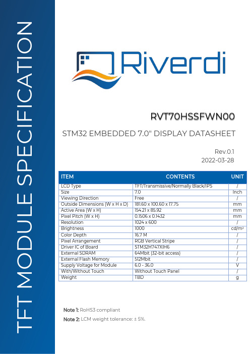
ITEM CONTENTS UNIT LCD Type TFT/Transmissive/Normally Black/IPS / Size 7.0 Inch Viewing Direction Free / Outside Dimensions (W x H x D) 181.60 x 100.60 x 17.75 mm Active Area (W x H) 154.21 x 85.92 mm Pixel Pitch (W x H) 0.1506 x 0.1432 mm Resolution 1024 x 600 / Brightness 1000 cd/m 2 Color Depth 16.7 M / Pixel Arrangement RGB Vertical Stripe / Driver IC of Board STM32H747XIH6 / External SDRAM 64Mbit (32-bit access) / External Flash Memory 512Mbit / Supply Voltage for Module 6.0 - 36.0 V With/Without Touch Without Touch Panel / Weight TBD g STM32 EMBEDDED 7.0" DISPLAY DATASHEET RVT70HSSFWN00 Rev.0.1 2022-03-28 F T M O D U L E S P E C I F I C A T I O N Note 1: RoHS3 compliant Note 2: LCM weight tolerance: ± 5%.REVISION RECORDREV NO. REV DATE CONTENTS REMARKS0.1 2022-03-28 Preliminary versionCONTENTSREVISION RECORD (2)CONTENTS (3)MODULE CLASSIFICATION INFORMATION (4)ASSEMBLY GUIDE (5)MODULE DRAWING (6)ABSOLUTE MAXIMUM RATINGS (7)ELECTRICAL CHARACTERISTICS (7)BACKLIGHT ELECTRICAL CHARACTERISTICS (7)ELECTRO-OPTICAL CHARACTERISTICS (8)BOARD INTERFACES AND CONNECTORS (10)USER INTERFACES (16)DISPLAY SEPCIFICATION (17)INSPECTION (17)RELIABILITY TEST (19)LEGAL INFORMATION (20)MODULE CLASSIFICATION INFORMATIONRV T 70 H S S F W N 00 1. 2. 3. 4. 5. 6. 7. 8. 9. 10.ASSEMBLY GUIDEMounting frameFor dimensions 3.5”, 4.3”, 5.0”, 7.0” and 10.1”, the product with mounting frame version is available. Thanks to the four catches attached to the side, frame provides strong assembly to the surface by mounting element (like the screw, see Figure 1). The frames are specially designed to fit Riverdi products perfectly. The diameter of the mounting hole is 3.5mm.Figure 1. Mounting frameABSOLUTE MAXIMUM RATINGSPARAMETER SYMBOL MIN MAX UNIT NOTESupply Voltage for Module VDD 0.0 48.0V Note 1Digital I/O signals Voltage - -0.5 3.3 Note 1,2Operating Temperature T OP-20 70 °CStorage Temperature T ST-30 80 °CStorage Humidity (@ 25 ± 5°C) H ST10 - % RHOperating Ambient Humidity (@ 25 ± 5°C) H OP10 - % RHNote 1. Exceeding maximum values may cause improper operation or permanent damageto the unit.Note 2. Most of the GPIOs have the 5.0 V tolerant input voltage, please refer to the datasheetof STM32H747XIH6 for more details.ELECTRICAL CHARACTERISTICSPARAMETER SYMBOL MIN TYP MAX UNIT Supply Voltage for Module VDD_IN 6.0 12.0 36.0 VPOWER‘ENABLE’ = ‘0’***************************I VDD_IN=6.0 V TBD TBD TBD uA ****************************I VDD_IN=12.0 V TBD TBD TBD uA ****************************I VDD_IN=24.0 V TBD TBD TBD uA ****************************I VDD_IN=36.0 V TBD TBD TBD uAPOWER‘ENABLE’ = ‘1’***************************I VDD_IN=6.0 V TBD TBD TBD mA ****************************I VDD_IN=12.0 V TBD TBD TBD mA ****************************I VDD_IN=24.0 V TBD TBD TBD mA ****************************I VDD_IN=36.0 V TBD TBD TBD mAInput Voltage “H” Level V IH 2.0 - 3.3 V Input Voltage “L” Level V IL 0 - 0.8 V Note. POWER ‘ENABLE’ refers to pin 4, ‘ENABLE’ of the power input connector(P2).By default, POWER ‘ENABLE’ = ‘1’,When POWER ‘ENABLE’ = ‘0’, the device is turned off.BACKLIGHT ELECTRICAL CHARACTERISTICSPARAMETER SYMBOL MIN TYP MAX UNIT NOTE Lifetime - - 50,000 - hours Note 1Note 1. Operating life means the period in which the LED brightness goes down to 50% ofthe initial brightness. Typical operating lifetime is the estimated parameter.ELECTRO-OPTICAL CHARACTERISTICSITEM SYMBOL CONDITION MIN TYP MAX UNIT RMK NOTEResponse Time Tr+Tfθ=0°∅=0° - 35 35 ms FIG 2. 4Contrast Ratio Cr 800 1000 - --- FIG 3. 1 Luminance δ- 75 - % FIG 3. 3 Figure 3.Contrast Ratio =Average Surface Luminance with all white pixels (P1,P2,P3,P4,P5) Average Surface Luminance with all black pixels (P1,P2,P3,P4,P5)Note 2.Surface luminance is the LCD surface from the surface with all pixels displaying white. For more information see Figure 3.Lv = Average Surface Luminance with all white pixels (P1, P2, P3, P4, P5)Note 3.The uniformity in surface luminance δWHITE is determined by measuring luminance at each test position 1 through 5, and then dividing the minimum luminance of 5 points luminance by maximum luminance of 5 points luminance. For more information see Figure 3.δ WHITE =Minimum Surface Luminance with all white pixels (P1,P2,P3,P4,P5) Maximum Surface Luminance with all white pixels (P1,P2,P3,P4,P5)Note 4. Response time is the time required for the display to transition from white to black (Rise Time, Tr) and from black to white (Decay Time, Tf). For additional information see Figure 2. The test equipment is Autronic-Melchers’s ConoScope series.Note 5. CIE (x, y) chromaticity, the x, y value is determined by measuring luminance at each test position 1 through 5, and then calculating the average value.Note 6. Viewing angle is the angle at which the contrast ratio is greater than 2. For TFT module the contrast ratio is greater than 10. The angles are determined for the horizontal or x axis and the vertical or y axis with respect to the z axis which is normal to LCD surface. For more information see Figure 4.Note 7. For viewing angle and response time testing, the testing data is based on Autronic-Melchers’s ConoScope series. Instruments for Contrast Ratio, Surface Luminance, Luminance Uniformity, CIE the test data is based on TOPCON’s BM-5 photo detector.Figure 2. The definition of response timeFigure 3. Measuring method for Contrast ratio, surface luminance, Luminance uniformity, CIE (x, y) chromaticityA: 5mmB: 5mmH, V: Active AreaLight spot size ∅=5mm, 500mm distancefrom the LCD surface to detector lens.Measurement instrument is TOPCON’Sluminance meter BM-5Figure 4. The definition of viewing angleBOARD INTERFACES AND CONNECTORSPower input connectorThe 1.25mm, 6-pin Molex connector labeled as “POWER’ (P2) is power input connector. There is an internal reverse polarity protection which ensures that the device is not damaged if the power supply polarity is reversed.NO. PIN DESCRIPTION NOTE1 VDD_IN Power supply input; 6.0-36.0VNote 12 VDD_IN Power supply input; 6.0-36.0V3 VDD_IN Power supply input; 6.0-36.0V4 ENABLE Enable/ Disable power supply. Note 25 GND Ground6 GND GroundNote 1: STM32 Embedded Display allows to directly connect one additional display to the system. There is RiBUS connector on the board where you can connect any of intelligent display from Riverdi based on EVE4 (BT817Q). However, please note that it may change power supply requirement as below:The power supply voltage must range between 7.0V- 14.0 V (TYP. 9.0 V), if Riverdi EVE4 10.1” series display is connected through RiBUS. At the same time, jumper P5 shall be configured according to subchapter 10.8, note 1.The power supply voltage ranges between 6.0 V- 36.0V if any of Riverdi EVE4 3.5”,4.3”,5.0” and 7.0” series display is connected through RiBUS. At the same time, jumper P12 shall be configured according to subchapter 10.8, note 1.Note 2: By default, pin “ENABLE” is pulled up to VDD and enabled. To disable, ground the pin to turn off the device completely.USB interfaceThe 1.25mm, 5-pin Molex connector labeled as “USB’ (P10) is USB interface.NO. PIN DESCRIPTION NOTE1 VCC_USB Power supply2 D- USB data-3 D+ USB data+4 ID USB OTG ID; Host /Device detect Note 15 GND GroundNote 1. Configuration of the USB Host/Device mode:Host Mode: Pin 4 (ID) should be connected to GND.In this mode, it can provide +5V output voltage to the connected USB device and Max output current 500 mA.Device Mode: Pin 4 (ID) should be not connected (floating).RS485 interfaceThe 1.25mm, 4-pin Molex connector labeled as “RS485’ (P3) is RS485 interface.NO. PIN DESCRIPTION NOTE1 VDD_IN Power supply input; 6.0-36.0V2 A Non-inverting receiver input and non-inverting driver output3 B Inverting receiver input and inverting driver output4 GND GroundRS232 interfaceThe 1.25mm, 5-pin Molex connector labeled as “RS232’ (P1) is RS232 interface.NO. PIN DESCRIPTION NOTE1 RTS Request to send2 CTS Clear to send3 TXD Transmit Data4 RXD Receive Data5 GND Ground2 x CAN FD interfacesThe main board supports 2 channels of the CANFD (Control Area Network Flexible Data-Rate) communication bus, based on the high-speed (2.5-8.0Mbps) CAN transceiver.2 pcs of 1.25mm, 4-pin Molex connectors labeled as “CAN1’ (P11) and “CAN2” (P15) are respectively interfaces of CAN FD1 and CAN FD2.NO. PIN DESCRIPTION NOTE1 GND Ground2 CAN_L CAN Low-Level Voltage3 CAN_H CAN High-Level Voltage4 VDD_IN Power supply input; 6.0 – 36.0 VHaptic feedback connectorThe 1.25mm, 2-pin Molex connector labeled as “HAPTIC’ (P7) is haptic feedback connector. Haptic feedback P7 is used to connect with the haptic motor directly.NO. PIN DESCRIPTION NOTE1 OUT- Negative haptic driver differential outputNote 12 OUT+ Positive haptic driver differential outputNote 1: The haptic driver DRV2605L is controlled directly by I2C protocolSWD (Serial Wire Debug) connectorThe 1.25mm, 6-pin Molex connector labeled as ‘SWD’ (P6) is SWD interface, which is used for programing the MCU on board.NO. PIN DESCRIPTION NOTE1 VCC_+3.3V Power input2 SW_CLK Serial wire clock3 GND Ground4 SW_DIO Serial wire debug data input/output5 RST Reset; Active low6 SWO Serial wire trace outputRiBUSAny size of the Riverdi EVE4 series display can be connected through RiBUS to act as a slave module to the mainboard.NO. PIN DESCRIPTION NOTE1 VCC_+3.3V Supply voltage for module; TYP3.3Vbetween 7.0 - 14.0V (TYP. 9V).For Riverdi EVE4 series display ranging from sizes of 3.5” to 7.0”, the backlight voltage (BLVDD) shall be 5.0V.Backlight jumper selectors, P5 and P12, labeled as “BLVDD SEL EXT”and “BLVDD SEL INT are used to configure the backlight voltage range.Warning! Jumper configuration shall be done when module is not powered.DO NOT change ANY jumpers while the module has power. Improper operation might cause permanent damage to the unit.Please pay special attention to not misplace the jumpers. Incorrect jumpers setting may lead to damage to the module as well.The P5, P12 jumpers setting are shown below.Table 1. Internal backlight selector P12 setting: 5.0V (default) backlight voltageSETTING P5, PIN 1 &2P5, PIN 3 &4P12, PIN 1 &2P12, PIN 3 &45.0V (Default) Open Open Short ShortTable 2. External backlight selector P5 setting: 7.0V-14.0V backlight voltageSETTING P5, PIN 1 &2P5, PIN 3 &4P12, PIN 1 &2P12, PIN 3 &47.0V - 14.0 V Short Short Open OpenExpansion connectorThe main board has one 1.27mm, 40-pin expansion pin header which is labeled as “EXPANSION CONNECTOR’ (P8).It provides direct access to below GPIOs of MCU STM32H747XIH6,which make it possible to easily extend a daughterboard for a specific application.• 2 x I2C• 1 x UART• 1 x USART• 1 x SPI• 1 x USB•7 x PWMs• 2 x DACs (Digital-to-analog)• 2 x ADCs (Analog-to-digital)Each of the GPIO pins can be configured by software as output (push-pull or open-drain, with or without pull-up or pull-down), as input (floating, with or without pull-up or pull-down) or as peripheral alternate function. Most of the GPIO pins are shared with digital or analog alternate functions. Please refer to the datasheet of MCU STM32H747XIH6 for more details.I/O/P PIN NAME NO. NO. PIN NAME I/O/PP VCC_+5V 1 2 VCC_+3.3V PP VCC_+5V 3 4 VCC_+3.3V PI/O PA5 5 6 GND PP GND 7 8 PA4 I/OI/O PE4 9 10 PD11 I/OI/O PK1 11 12 PB10 I/OI/O PD12 13 14 PC7 I/OI/O PD13 15 16 PA3 I/OP GND 17 18 GND PI/O PC2 19 20 PA0_C I/OI/O PC3 21 22 PA1_C I/OI/O PA12 23 24 PC2_C I/OI/O PA9 25 26 PC3_C I/OI/O PA10 27 28 GND PI/O PJ8 29 30 PC13 I/OI/O P18 31 32 PA8 I/OI/O PJ10 33 34 PB11 I/OI/O PB0 35 36 PH4 I/OI/O PC6 37 38 PB12 I/OI/O PB14 39 40 PB15 I/ONote 1. ***************************from pin 1 and pin3 is maximum 1A.********************************************************.Note 2.The ‘USR LED’ is connected to pin 33, PJ10, of the expansion connector.By default, the resistor R60, (0402, 1k ohms) is soldered. Please remove R60 to useGPIO channel PJ10.Note 3. Push button BTN2(S2) is connected to pin 35, PB0, of the expansion connector. Please remove R58 to use GPIO channel PB0.Push button BTN1(S1) is connected to pin 37, PC6, of the expansion connector.Please remove R57 to use GPIO channel PC6.Micro SD slotThe mainboard is equipped with Micro-SD slot, which supports all types of Micro SD cards.2 x 20-pin, 1.27 mm pin sockets for POE Add-on BoardThe 2 x 20-pin, 1.27 mm, pin sockets, labeled as U9a and U9b, are used to connect the Riverdi POE Add-on Board.The Riverdi POE Add-on Board features 10/100M Ethernet Port with Power-Over-Ethernet enabled. It allows you to power the module through the Ethernet port.Note. The Riverdi POE Add-on Board is offered as an accessory.USER INTERFACES3 x push buttonsPush button labeled as “RST” is used to “RESET” the module.Another 2 push buttons labeled as BTN1, BTN2 are for user’s development.•BTN1(S1) is connected to pin 37, PC6, of the expansion connector.•BTN2(S2) is connected to pin 35, PB0, of the expansion connector.By default, pushbuttons BTN1(S1), BTN2(S2) are enabled. To use GPIO channel PC6 and PB0, R57 and R58 should be removed.3 x LEDs1 x LED, labeled as ‘PWR LED’, emits green light when the modules is powered.1 x LED, labeled as ‘USB OVR’, emits red light when VCC_USB pin is shorted.1 x LED, labeled as ‘USR LED’, is for user’s development.•The ‘USR LED’ is connected to pin 33, PJ10, of the expansion connector.By default, the resistor R60, (0402, 1k ohms) is soldered. Please remove R60 to use GPIO channel PJ10.D ISPLAY SEPCIFICATIONTFT resolutionThe supported resolution of the display in this module is 1024*600.Full TFT specificationFor detailed information on the display, please refer to datasheet of displayRVT70HSMFWN00.I NSPECTIONStandard acceptance/rejection criteria for TFT moduleInspection conditionAmbient conditions:•Temperature: 25 ± 2°C•Humidity: (60 ± 10) %RH•Illumination: Single fluorescent lamp non-directive (300 to 700 lux) Viewing distance: 35 ± 5cm between inspector bare eye and LCD.Viewing Angle: U/D: 45°/45°, L/R: 45°/45°Inspection standardITEM CRITERIONBlack spots,white spots,light leakage,Foreign Particle(round Type)D=(x+y)/2Spot’s density: 10 mmSize = 7”Average Diameter Qualified QtyD ≤ 0.2 mm Ignored0.2 mm < D ≤ 0.3 mm N≤30.5mm < D Not allowed 0.5mm < DLCD black spots, white spots, light leakage (line Type)Size = 7”Length Width Qualified Qty - W ≤ 0.05IgnoredL ≤ 5.00.05 < W ≤ 0.1 35.0 < L 0.1 < W Not allowedBright/Dark DotsSize = 7”Item Qualified Qty Bright dots N≤2Dark dots N≤3 Total bright and dark dots N≤4Clear spotsSize = 7”Average Diameter Qualified QtyD < 0.2 mm Ignored0.2 mm < D < 0.3 mm 40.3 mm < D < 0.5 mm 20.5 mm < D 0Polarizer bubblesSize = 7”Average Diameter Qualified QtyD ≤ 0.2 mm Ignored0.2 mm < D ≤ 0.5 mm 40.5 mm < D 0Touch panel spotSize ≥ 5"Average Diameter Qualified QtyD < 0.25 mm Ignored0.25 mm < D < 0.5 mm 40.5 mm < D 0Touch panel White line ScratchSize ≥ 5’’Length Width Qualified Qty - W < 0.03 IgnoredL < 5.0 0.03 < W < 0.05 2- 0.05 < W 0RELIABILITY TESTNO.TEST ITEMTEST CONDITIONNOTE1 High Temperature Storage 80°C/120 hoursNote 12 Low Temperature Storage -30°C/120 hours3 High Temperature Operating 70 °C /120 hours Note 2. Before cosmetic and function test, the product must have enough recovery time, at least 2 hours at room temperature.L EGAL INFORMATIONRiverdi grants the guarantee for the proper operation of the goods for a period of 12 months from the date of possession of the goods. If in a consequence of this guaranteed execution the customer has received the defects-free item as replacement for the defective item, the effectiveness period of this guarantee shall start anew from the moment the customer receives the defects-free item.Information about device is the property of Riverdi and may be the subject of patents pending or granted. It is not allowed to copy or disclosed this document without prior written permission.Riverdi endeavors to ensure that all contained information in this document is correct but does not accept liability for any error or omission. Riverdi products are in developing process and published information may be not up to date. Riverdi reserves the right to update and makes changes to Specifications or written material without prior notice at any time. It is important to check the current position with Riverdi.Images and graphics used in this document are only for illustrative the purpose. All images and graphics are possible to be displayed on the range products of Riverdi, however the quality may vary. Riverdi is no liable to the buyer or to any third party for any indirect, incidental, special, consequential, punitive, or exemplary damages (including without limitation lost profits, lost savings, or loss of business opportunity) relating to any product, service provided or to be provided by Riverdi, or the use or inability to use the same, even if Riverdi has been advised of the possibility of such damages.Riverdi products are not fault tolerant nor designed, manufactured or intended for use or resale as on line control equipment in hazardous environments requiring fail–safe performance, such as in the operation of nuclear facilities, aircraft navigation or communication systems, air traffic control, direct life support machines or weapons systems in which the failure of the product could lead directly to death, personal injury or severe physical or environmental damage (‘High-Risk Activities’). Riverdi and i ts suppliers specifically disclaim any expressed or implied warranty of fitness for High-Risk Activities. Using Riverdi products and devices in 'High-Risk Activities' and in any other application is entirely at the buyer’s risk, and the buyer agrees to def end, indemnify, and hold harmless Riverdi from all damages, claims or expenses resulting from such use. No licenses are conveyed, implicitly or otherwise, under any Riverdi intellectual property rights.。
基于STM32系统的智能语音控制的垃圾桶设计
基于STM32系统的智能语音控制的垃圾桶设计苏珍康学亮马飞虎(北方民族大学,宁夏银川750021)摘要:随着计算机技术与电子科技的快速发展,人工智能、云计算等技术的不断进步,智能家居新型产业模式也得到了巨大的发展,至今国内智能家居市场投资达到了1396亿元,市场规模占比不断增大,未来十年内家居智能化将实现大规模应用。
鉴于此,设计了一种智能语音控制垃圾桶,能根据人发出的指令做出判断,运行到指定位置,收取完垃圾之后再回到起点位置。
关键词:智能家居;STM32;嵌入式;人工智能0引言随着人们生活起居水平的提高、社会的发展和经济水平的不断提升,人们对生活的要求更趋于个性化、定制化、自动化,对生活的便捷及乐趣有了更高的要求。
在平时生活中,扔垃圾是再简单不过的一件事情,但也会给人们带来不必要的麻烦。
比如,吃东西的时候不想走动,但也不想放一个垃圾桶在身边。
为解决这样的问题,此项目设计了一款能用语音控制、自动寻迹的垃圾桶。
该设计的主控系统采用STM32单片机,能够识别特定的语音指令,将语音信息转换为电信号给主控系统进行处理,主控系统在处理语音信息的基础上,判断在哪个位置有人需要,不再需要人们特意走动到垃圾桶边去扔垃圾。
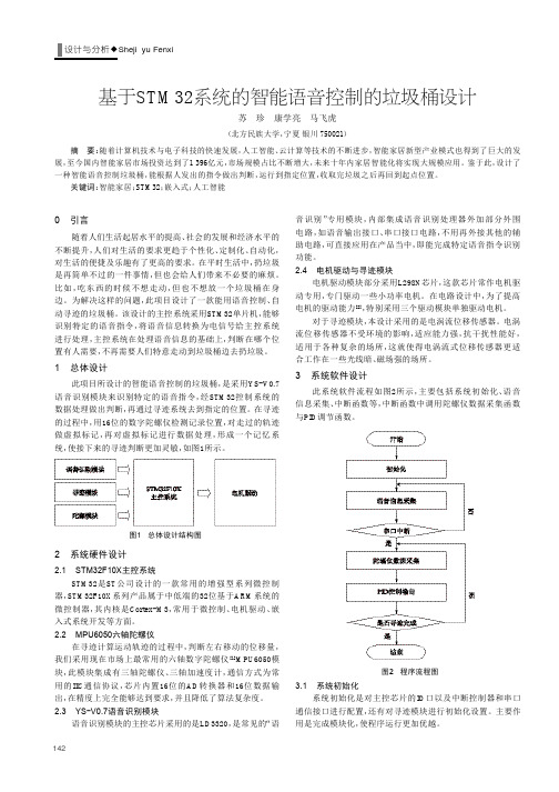
1总体设计此项目所设计的智能语音控制的垃圾桶,是采用YS -V0.7语音识别模块来识别特定的语音指令,经STM32控制系统的数据处理做出判断,再通过寻迹系统去到指定的位置。
在寻迹的过程中,用16位的数字陀螺仪检测记录位置,对走过的轨迹做虚拟标记,再对虚拟标记进行数据处理,形成一个记忆系统,使接下来的寻迹判断更加灵敏,如图1所示。
2系统硬件设计2.1STM32F10X 主控系统STM32是ST 公司设计的一款常用的增强型系列微控制器,STM32F10X 系列产品属于中低端的32位基于ARM 系统的微控制器,其内核是Cortex -M3,常用于微控制、电机驱动、嵌入式系统开发等方面。
2.2MPU6050六轴陀螺仪在寻迹计算运动轨迹的过程中,判断左右移动的位移量,我们采用现在市场上最常用的六轴数字陀螺仪[1]MPU6050模块,此模块集成有三轴陀螺仪、三轴加速度计,通信方式为常用的IIC 通信协议,芯片内置16位的AD 转换器和16位数据输出,在精度上完全能够达到要求,并且降低了算法复杂度。
一种基于Arduino的智能家居控制系统

一种基于Arduino的智能家居控制系统一种基于Arduino的智能家居控制系统摘要:介绍了一种基于Arduino的智能家居控制系统,利用Arduino作为主控系统,结合传感器技术、GSM通信技术、语音控制技术等实现对家居环境中的温湿度、空气质量、照明设备、家电设备等的智能控制。
该系统具有无线控制的功能,操作方便,成本低,适合大量推广使用。
关键词:Arduino;智能家居;无线控制1984年世界上第一幢智能建筑在美国康涅迪格州出现。
它将家庭中各种与信息相关的通信设备、家用电器和家庭保安装置连接到一个家庭智能化系统中进行集中的或异地的监视、控制和家庭事务性管理,并保持这些家庭设施与住宅环境的和谐与协调[1]。
如今这种建筑正成为都市人青睐的家居体验方式。
2003年以来,海信、清华同方等公司也相继加入到智能家居行列,但目前的智能家居系统还缺乏统一明确的国际标准,许多公司开发出的产品都是基于自己组建的网络和信息交换协议,很多产品是针对特定的组网环境开发的,部分核心技术没有对外公布,技术复杂,直接导致了使用范围的局限性。
由于缺乏对应的第三方产品,各个接入设备之间不能兼容,互操作性差,不利于产品的扩充。
1系统的硬件设计以电子系统为核心的家居系统是未来智能家居的发展趋势[2],本文介绍一种基于Arduino 的智能家居控制系统。
建立智能家居控制系统,硬件是关键和基础,它对整个系统的稳定性、控制和反馈的准确性、节能性都有直接影响[3]。
智能家居控制系统的硬件部分主要包括Arduino控制器、传感系统、无线控制系统、语音播报部分和液晶显示等。
其中,传感器部分由温湿度传感器和气体传感器三部分组成,用以检测室内温湿度及有害气体。
无线控制部分由GSM和无线语音控制模块两部分组成。
系统结构。
1.1Arduino控制器Arduino是一个开源的单片机电子设计平台,硬件部分由Atmel AVR单片机、I/O接口及相关电路组成,软件部分则包括标准的程序编译器和程序下载器,具有使用类似Java 和C语言的Processing/Wiring开发环境[4]。
TIptop Audio MIX7 7-通道单声道汇合混音器说明书
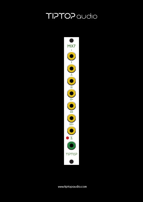
MIX7MIX7 is a 7-channel mono summing mixer in Eurorack format that can be used to mix audio, CV, Triggers or Gate signals. There are two modes of operation that are set by a jumper at the back of the module.Unity gain (JUMPER OFF: OUT = IN): The level of each input equals that of the output, what comes in comes out.Attenuated gain (JUMPER ON: OUT = 0.4IN): The level of each input is attenuated at the output to provide more headroom for mixing hot (loud) audio signals without distortion.The module is shipped in Unity mode, with the jumper o .MIX7 can be used in multiple ways, so lets get started:Drum MixerSequence a drum pattern with up to 7 drum sounds, connect the audio output of each drum module to an input of MIX7. Connect the output of MIX7 to your sound system. Use individual volume controls on drum modules to set the drums balance.Mixing Oscillators WaveformConnect the waveforms from two Z3000’s to the inputs of MIX7. Connect the mix output of MIX7 to your sound system through a Filter like the Z2040. You have just patched the audio part of a monophonic synth patch.Mixing Control Voltage SourcesIn this example we will need two Z4000 envelopes. Connect the outputs of both to the inputs of MIX7. Connect the mix output of MIX7 to your Frequency Modulation (FM) input of Z2040 lter. Now you can modulate the lter frequency with two envelopes.Mixing Triggers And GatesConnect the trigger outputs from your Circadian Rhythms or Trigger Riot to di erent inputs on the MIX7, send the MIX OUT to a Tiptop Audio ONE Sample Player, play with the Mute button on the sequencers to add and remove triggers from the mix.Mixing More Than 7 ChannelsMIX7 is a summing bus that can be expanded by using two or more MIX7 modules to add channels. Connect the output of the rst MIX7 to input 1 on the second MIX7. Connect the output of the second MIX7 to your sound system. Now you have patched a 13-channel mixer.Modes And Jumper SettingsThere are two modes of operation that are set by a jumper at the back of the module. With the jumper set on one pin or none of the pins the mode is set to Unity Gain, this is how your MIX7 is set by us when shipped to you. With the jumper set on two pins the mode is Attenuated Mode. On the back of the module the options appear as:JUMPER OFF: OUT = INJUMPER ON: OUT = 0.4 INMode 1 - Unity gain: the level of each input equals that of the output, what comes in comes out. This is the standard mode typical to modular synthesizer mixers. This mode is transparent with no added gain and can be used with all type of signals.Mode 2 - Attenuated Gain: the level of each input is attenuated before it gets mixed to provide more headroom for mixing hot (loud) audio signals without distortion. This mode should be con-sidered if you are planning to use MIX7 primarily for mixing hot signals like Tiptop drums and ONE Sample Player modules, giving you peace of mind knowing there is little chance of clipping the signals even when the volume levels of the sounds feeding the mixer are high. Mixing of audio signals with no distortion and clipping is essential for quality mixing, for example when mixing bass drums. In many cases bass drums are pure sine waves. If these waves are getting clipped, the bass drum gets added harmonics that change its purity. This can lead to a unintentionally distor-ted bass drum instead of a well-rounded one. Clipping is indicated by the RED led on the module.Mode 1Mode 2Processing Drums In GroupsBy using two or more MIX7 it’s easy to create ''subgroups''. Subgroups are used to process groups of di erent sounds simultaneously. For example you can mix bass drums, toms and snare together using one MIX7 and Hi Hats and cymbals using another MIX7.1. Connect the output of the rst MIX7 to a High Pass input on Forbidden Planet and theoutput of the second MIX7 to a delay.2. Connect MIX7 outputs to the inputs on a third MIX7.3. Connect the output of the third MIX7 to your sound system.Now you have split your drum sounds into two separate processing groups: High-Pass lter on low and mid-range drums and delay on cymbals and hi hats. This is a typical work ow of signal routing and sound design inside the modular.Mixing Oscillator Waveforms1. Tune your Z3000 oscillator to a nice bass frequency.2. Connect square wave to input 1 on MIX7.3. Connect sine wave output of a second Z3000 tuned one octave lower than the rst tochannel 2 of MIX7.4. Connect mix output of MIX7 to the input of Z2040 lter.5. Connect the output of Z2040 to your sound system.Now you have a square wave tone reinforced by a sub bass sine wave that you can lter to taste.A variation on the patch described above.1. Tune your Z3000 oscillator to a nice bass frequency.2. Conne.ct square wave output to the input of Z2040.3. Connect the output of Z2040 to input 1 on MIX7.4. Connect sine wave output of a second Z3000 tuned one octave lower than the rst tochannel 2 of MIX7.5. Connect mix output of MIX7 to your sound system.Now you have a square wave tone that you can lter to taste reinforced by a sub bass sine wave that is ltered separately.Mixing Control Voltages1. Connect saw wave output of Z3000 to the audio input of Z2040, connect the output ofZ2040 to your sound system.2. Connect the output of Z4000 ADSR envelope to input 1 on MIX7.3. Connect the output of a second Z4000 to input 2 on MIX7.4. Connect the output of a third Z4000 to input 3 of MIX7.5. Connect the 16 step output of Z8000 to input 4 of MIX7.6. Connect the mix out of MIX7 to the frequency modulation input of Z2040.Trigger the 3 envelopes from 3 separate tracks of Circadian Rhythms, clock Z8000 from the main Circadian Rhythms clock output. Now run the sequence. By creatively arranging your gate patterns that trigger the envelopes and mixing in modulation sequence you cancreate very interesting modulation patterns.Connect The Sound Of Your Mobile Phone To Your ModularMIX7 can even be used to amplify a weak signal. It’s not the ideal way of doing that, but what hap-pens if you don’t have a dedicated ampli er module handy? Use Stackcables to send your phone audio to all 7 inputs on MIX7, (make sure MIX7 is set to UNITY MODE). MIX7 has now multiplied the gain of your phone by 7, making it usable for use in the modular.。
联想天工语音产品系列用户手册
联想天工语音产品系列用户手册目录1. 系统说明 (4)1.1 系统终端 (4)1.2 系统业务 (4)1.2.1 补充业务 (4)1.2.2 IVR业务 (5)1.3 缩略语 (5)2. 模拟用户使用说明 (6)2.1 呼叫转移业务的使用 (6)2.1.1 全转移 (6)2.1.2 遇忙转移 (6)2.1.3 无应答转移 (7)2.2 呼叫转接业务的使用 (7)2.3 呼叫保持业务的使用 (8)2.4 呼叫等待业务的使用 (8)2.5 信息等待指示业务的使用 (9)2.6 免打扰业务的使用 (9)2.7 呼出限制业务的使用 (10)2.8 热线业务的使用 (10)2.9 电话查号的使用 (11)2.10 记账卡业务的使用 (11)2.11 留言和提取留言 (12)2.11.1 机主留言 (13)2.11.2 来话留言 (13)2.11.3 留言本地提取 (14)2.11.4 留言异地提取 (14)2.12 定时邮送业务的使用 (14)2.13 自动查号功能的使用 (15)3. Mswitch 语音通信的网管系统使用 (15)3.1 如何登录网管系统 (15)3.2 查看用户通用属性 (16)3.3 时段服务和用户等级设置说明 (18)3.4 使用网管系统设置补充业务 (19)3.5 使用网管系统设置语音信箱参数 (24)3.6 如何修改登录网管系统的用户名称和密码 (25)3.7 重新登录和退出网管系统系统 (26)4. IVR使用说明 (27)4.1 电脑话务员业务 (28)4.1.1 呼叫转接 (28)4.1.2 内部用户查号 (31)4.2 语音信箱业务 (31)4.2.1 进入语音信箱 (32)4.2.2 进入主菜单 (32)4.2.3 机主留言 (33)4.2.4 修改信箱密码 (34)4.2.5 信箱操作 (34)4.2.6 来话留言 (36)4.2.7 定时邮送 (37)4.3 语音邮件业务 (39)4.4 留言通知 (40)4.4.1 操作方法 (40)4.4.2 提示方法 (40)5. Shell使用说明 (41)5.1 命令格式的表示习惯 (41)5.2 Shell命令的设置说明 (41)5.3 Shell命令格式一览表 (42)5.4 Shell命令及使用说明 (46)5.5 Shell命令帮助使用 (46)5.6 Shell命令的快捷使用 (47)5.7 登录系统 (48)5.8 exit 退出系统 (48)5.9 reboot 重新引导系统 (49)5.10 version显示软/硬件信息 (49)5.11 software 升级软件 (50)5.12 password 更改系统登录密码 (50)5.13 date 显示/设置系统日期 (51)5.14 time 显示/设置系统时间 (52)5.15 netconfig 网络配置 (53)5.16 portconfig 端口配置 (56)5.17 sysconfig 系统配置 (58)5.17.2 sysconfig dialplan 拨号计划配置 (60)5.17.3 sysconfig huntgroup 连选组配置 (62)5.17.4 sysconfig huntedit 编辑连选组 (63)5.17.5 sysconfig gain 收/发增益配置 (64)5.17.6 sysconfig atd 人工总机配置 (66)5.17.7 sysconfig cmid CMID配置 (66)5.17.8 sysconfig factory恢复出厂默认配置 (67)5.17.9 sysconfig testdata恢复默认测试配置 (68)5.18 h323 协议栈h323配置 (68)5.18.2 h323 ras RAS方式配置 (70)5.18.3 h323 faststart 快速建立配置 (71)5.18.4 h323 dtmf DTMF转发方式配置 (72)5.18.5 h323 h450 H450配置 (73)5.19 dtconfig 数字中继配置 (74)5.19.2 dtconfig synch 时钟跟踪方式配置 (75)5.19.3 dtconfig signaling信令类型配置 (76)5.19.4 dtconfig isdn ISDN信令配置 (77)5.19.5 dtconfig no1 No1信令配置 (80)5.20 tkdirection 中继方向配置 (82)5.21 voice 语音配置 (83)5.21.2 voice codec 默认编码方式配置 (85)5.21.3 voice g7231 g.723.1编码方式配置 (86)5.21.4 voice g711a g.711a律编码方式配置 (87)5.21.5 voice g711u g.711μ律编码方式配置 (88)5.21.6 voice g729 g.729编码方式配置 (89)5.21.7 voice jittertbuffer 抖动缓冲区大小配置 (90)5.21.8 voice vad 静音压缩配置 (91)5.21.9 voice default恢复语音信息默认配置 (92)5.22 route 路由配置 (93)5.22.2 route static 静态路由配置 (94)5.22.3 route rip RIP协议配置 (96)5.23 qos QOS配置 (97)5.23.2 qos 8021 802.1p/q配置 (99)5.23.3 qos tos TOS配置 (100)5.24 greeting下载电脑话务员提示语音 (100)5.25 ping测试主机连接 (101)5.26 pbook 电话号码本配置 (102)5.27 gatekeeper GateKeeper配置 (104)5.28 debug 调试信息配置 (105)5.29 status 系统状态显示 (109)5.30 t38 T38配置 (109)5.31 billing 计费配置 (110)5.32 standby 切换为备用状态 (111)5.33 pair 另一个CM配置 (112)5.34 log 操作日志 (112)5.35 prompt 修改提示符名称 (113)5.36 console 维护台控制 (113)5.37 compatible 兼容配置 (114)5.38 stack协议栈信息显示 (114)5.39 sysmem系统内存信息显示 (115)5.39.1 显示系统内存信息 (115)1. 系统说明Mswitch 语音通信采用新一代的基于网络的交换技术,采用全分布式控制方式,既提高系统的可靠性,又减少了网络通信的数据量,从而最大限度的减少网络带宽占用。
NewWay语音识别模块硬件使用指南

外接 IO 接口
为普通输出和推挽输出。设置 成推挽输出时可以提供更大的 驱动电流,但是需要接 1K 以上 限流电阻.
NewWay 电子----专业电子模块开发、生产、供应商
newway Electronics .LTD 联系方式:13770950403
IO(n) :第 n 个 IO 输出接口, VCC:电源正极(此处没有电源 反接保护,无法作为电源输入, 只能做输出使用) GND:电源负极 在启动时,如果按下功能按钮 模块将启动下载模式,此时可 功能按钮 以用于设置和语音向模块内下 载。在使用过程中,如果把模 块设置为单次识别触发,按下 该按键时将启动一次识别过程 可接喇叭,标注“+”的接喇叭 喇叭接口 正极,标注“-”的接喇叭负极 功放/耳机接口 模块立体声输出接口,可以接 耳机或者通过录音线接到功放 外接麦克风接口 可以外接麦克风 TTL 串行接口, 可以直接接到单 片机。 VCCOUT:模块电源输入(输入范 TTL 串口 围 DC 4-16 V),如果电源接口 已经电源,此接口不能接任何 电源,以免产生冲突,损坏器
7.识别触发方式
语音识别模块有两种触发方式,一种是按键触发, 一种是循环触发. 7.1 按键触发 按键触发是一种单次的语音识别触发,使用按键触 发时,上电后当模块初始化完毕后,将启动一次初始模 块识别过程,在识别过程中,如果按下功能按键,将重 新启动识别过程,在识别过程结束后,模块将进入等待 状态,等待下一次按键的按下。如果识别完成后有模态 转移,那么该模态将自动启动。 7.2 循环触发 在循环模式下,系统将自动的启动识别,无需人为 干预
NewWay 电子----专业电子模块开发、生产、供应商
newway Electronics .LTD 联系方式:13770950403
- 1、下载文档前请自行甄别文档内容的完整性,平台不提供额外的编辑、内容补充、找答案等附加服务。
- 2、"仅部分预览"的文档,不可在线预览部分如存在完整性等问题,可反馈申请退款(可完整预览的文档不适用该条件!)。
- 3、如文档侵犯您的权益,请联系客服反馈,我们会尽快为您处理(人工客服工作时间:9:00-18:30)。
飞音云电子技术支持:751956552@ 网络销售:乐声001(阿里旺旺
ID)YS-V0.7一体化语音识别模块使用手册
模块实物图
目录
1、初次使用测试步骤
2、配套程序识别命令修改步骤
3、与单片机设备串口通讯
4、程序下载说明
5、其他说明
飞音云电子技术支持:751956552@ 网络销售:乐声001(阿里旺旺ID)
1、初次使用测试步骤
(1)按照图1所示(P4接口),连接USB 下载器,接上GND 、RXD 、TXD 、5V (VCC 端口为3.3V 输出,方便为其他设备提供电源,在此不接),注意RXD/TXD 必须交叉连接,才能进行一收一发通信,在PC 机上打开串口调试工具,设定波特率为9600bit/s 。
(2)将USB 下载器连接到PC 机,查看该下载器在PC 机中占用的串口通道,然后对应选择调试工具的串口号,设定
后,重新给模块通上电源(拔下GND 连接线,再重新连接,即可以重新上电,下载程序时冷启动也是一样的操作),这时,调试工具接收窗口将打印出相关口令。
(3)本模块出厂默认下载的是口令模式程序,用户根据串口所示的口令内容,先对着咪头发一级口令(“小捷”),待板上的D1灯点亮后,可以开始对其他二级口令的识别,如此循环操作识别。
识别操作。
如识别成功,则有相关反馈信息。
(4)调试完毕
(5)测试好模块后可以与其他单片机设备进行通讯,连接方式和测试方法与在PC 机调试一样。
如不了解51单片机如何下载和调试的请查看“YS-USB to
TTL 下载器(图
1)
飞音云电子技术支持:751956552@ 网络销售:乐声001(阿里旺旺ID)
使用手册.pdf ”
2、配套程序识别命令修改步骤
(1)添加关键词和识别码
打开程序,在LDChip.C 文件中找到
uint8LD_AsrAddFixed()函数,在该函数里面可以找到如下图所示内容:
----根据关键词的数量和长度修改宏定义DATE_A 和DATE_B ,例如您要添加10个关键词,在这些关键词中最长的一句长度为30,那么定义如下:
#define
DATE_A 10#define DATE_B 30
---sRecog[][]数组为关键词数组,添加内容为拼音输入方式,例如想添加“开灯”命令,则写入“kai deng ”,每个汉字间的拼音用空格隔开。
---pCode[]数组为识别码数组,所添加的识别码为预先定义好的宏定义常量值,同时必须和关键词一一对应,如上图所示,“da ma ce
飞音云电子技术支持:751956552@ 网络销售:乐声001(阿里旺旺ID)
shi ”命令对应的识别码为CODE_DMCS 。
(2
)定义识别码打开程序,在LDChip.h 文件中找到如下图所示内容:
---
此处即为识别码的添加和修改,用户可以根据自己的需要和喜好任意定义识别码和宏名,但必须和前面所使用的识别码配对,否则会提示未定义错误。
(3)修改处理函数
打开程序,在main.c 文件中找到void User_handle(uint8dat)函数,在该函数中可以看到如下图所示内容:
飞音云电子技术支持:751956552@ 网络销售:乐声001
(阿里旺旺ID)
---用户可以根据自己的使用情况在相对应的识别码后添加识别成功后的操作。
3、与单片机设备串口通讯
本模块可以根据个人需要嵌入到自己的产品中,如果产品功能简单可尝试利用本模块自带的IO 口进行外部连接控制。
同时还可以通过串口与产品中的单片机进行串口通信达到控制效果,如采用这种方式进行控制,用户可以对main.c 函数中的处理函数进行修改,将输出的信息更改为输出识别码,那么在每次识别成功后串口都将打印输出对应的识别码,产品中的单片机就可以对该识别码进行操作以达到控制效果。
4、程序下载说明
本模块程序的下载与STC 系列单片机下载方法一
飞音云电子技术支持:751956552@ 网络销售:乐声001(阿里旺旺ID)
致,采用USB 转TTL 下载器或者电脑串口转MAX232下载器进行下载程序,注意连接上模块的G(gnd)、RX(RXD)、TX(TXD)、5V ,其中RX/TX 必须和下载器交叉连接,模块上引出排针的VCC 端口为3.3V 供有需要的用户供电使用,一般情况下该端口不做任何连接。
5、其他说明
本模块除语音识别部分外,其余与普通的单片机操作一样,在程序方面只要保持驱动程序不改动,其余的操作亦和单片机操作一样,模块具备的IO 口属单片机IO 口,本模块配套的程序主要针对语音识别功能的应用,如用户测试完毕,可以将config.h 文件中的定义进行注销,程序将不再输
出提示信息。
剩余的相关单片机操作用户根据自己的需要和应用自行开发应用。
飞音云电子技术支持:751956552@ 网络销售:乐声001(阿里旺旺ID)
备注:使用者可以在了解本程序的情况下进行程序改动,带有
/*text****/文本标志部分可以删除,其余寄存器配置必须在了解模块工作原理后进行修改,只作为进一步感性了解。