ansys宏命令
ansys命令详解
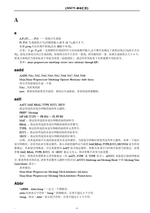
ansys命令详解《ANSYS命令汇总》AaA,P1,P2,........P18 ――连接点生成面P1-P18 生成面的点号(用键盘输入,最多18个),最少3个, 如果p1=p,可以在图中拾取(仅在GUI中有效)注意:点p1到p18一定按顺时针或逆时针方向沿面顺序输入,这个顺序也确定了面的法线正向(按右手法则)。
面包含相邻点间已生成的线,如果两点间不只存在一条线,将用最短的一条。
如果生成面的点大于4个,要求点和线在当前坐标系下坐标为常值(如面或柱)。
建议环形坐标系下实体建模不用此命令。
菜单:main>preprocessor>modeling>create>area>arbitrary>through KPsaaddAADD, NA1, NA2, NA3, NA4, NA5, NA6, NA7, NA8, NA9Main Menu>Preprocessor>Modeling>Operate>Booleans>Add>Areas 将分开的面相加生成一个面 NA1...为原来的面note:要相加的面要是共面的,相加后生成新面,原来的面将被删除,aattAATT, MAT, REAL, TYPE, ESYS, SECN 指定所选的未划分网格的面的单元属性。
PREP7: MeshingMP ME ST DY <> PR EM <> FL PP EDMAT :指定给所选的未划分网格的面的材料号。
REAL :指定给所选的未划分网格的面的实常数号。
TYPE:指定给所选的未划分网格的面的单元类型号。
ESYS :指定给所选的未划分网格的面的坐标系号。
SECN :指定给所选的未划分网格的面的区域号。
注释:从所选的面中生成的面也将具有这些属性。
当面划分网格时将使用这些单元属性。
如果一个面在划分网格时,没有用此命令指定属性,那么该面的属性由当前的MAT,REAL,TYPE,ESYS,SECNUM命令的设置确定。
ANSYS命令流、二次开发与HELP文档(介绍)
ANSYS命令流、二次开发与HELP文档(一)ANSYS在操作时有两种途径,一种是GUI途径,即通过ANSYS可视化的操作菜单来实现对分析过程的操作,而另外一种就是所谓的命令流,这更像是一种后台操作,操作者分析的过程即是将一条条ANSYS命令按照自己的分析思路组织起来,而ANSYS通过调用这些命令完成分析。
初学ANSYS的人,对命令流充满了迷惑,因为当拿出一个分析过程自动形成的.log文件之后发现一行一行犹如天书,但这些正是ANSYS命令的真实面目,而我们常使用的菜单操作只不过是把这些命令的本来面目给遮盖起来了,在学习ANSYS的过程中,随着学习过程的深入,加之以对命令流本身有个追本溯源的原动力驱使,命令流本身也不是很难。
命令流与菜单操作相比各有其优缺点,学习ANSYS一般从菜单操作开始,因为菜单操作能够做到于使用者直接对话,简洁和可视化,但其缺点是如果一直按照菜单操作的方式进行便不能窥视到ANSYS的工作过程,尤其是在进行同个问题变换其中一个或几个参数进行分析时,其重复操作的工作太多,大大减小了分析的趣味性,把精力放在了没有技术含量的操作上。
ANSYS命令流则弥补了这一缺陷,虽然难以理解,但当使用命令流进行分析时,能够大大的缩短分析的手工工作量,尤其是配合一定APDL语句,能够使分析过程自动进行,而操作者要做的仅仅是调用已经编制好的命令流文件而已,这时操作者的精力将会是放在对整个分析过程的分析和研究上,因为一旦分析过程研究及其实现机理研究透彻,那随之而来的所谓分析只是计算机自己的问题,操作者可以调用完命令之后随心所欲的做其他事情,而且学习命令流可以更好的理解ANSYS的工作过程和分析机理,这是菜单操作方式所没有的,我们在学习ANSYS过程中,菜单操作仅仅是对ANSYS使用环境熟悉的一个过程。
谈到命令流的种种优点,便引起这样一个问题,如何学习ANSYS命令流?更确切的说如何入门命令流?学习ANSYS的人会发现,初学ANSYS命令流会感到无从下手,不知道该如何去进入这个世界,好像是ANSYS命令流的世界只有一个很小的门,大多数人都钻不过去,只有少数人钻了过去看到了里面的美妙景象,其实来说命令流的世界没有想象的这么难以进入。
如何学习ANSYS命令流及APDL简解
(编辑器选择)
LOG文件的秘密
3
Dare Design 2014
什么是ANSYS命令流,
APDL是什么?
• ANYS提供两种工作方式,GUI图形用户界面(Graphical User Interface又称图形用户接口)操作和命令流。 • 在ANSYS 中,命令流是由一条条ANSYS 的命令组成的一个 命令组合,这些命令按照一定顺序排布,能够完成同GUI方 式一样甚至GUI不能完成的的 操作。 • 命令流方式融GUI方式、APDL、UPFs、UIDL、MAC,甚 至TCL/TK于一个文本文件中,可通过/input命令(或Utility Menu>File>Read Input From)读入并执行,也可通过拷 贝该文件的内容粘贴到命令行中执行。
12
Dare Design 2014
上篇
简介及准备
编辑器选择 >
常用的文本编辑器,UltraEdit和PSPad
13
Dare Design 2014
上篇
简介及准备
编辑器选择 >
选择编辑器的原因: •强大的数据处理能力、文件对 比、替换、列选等 •语法高亮 PSPad还具有自动完成功能。 UE 9.0c版体积小,绿色版,大 文件打开速度快,很EASY的列 选及列操作。 PSPad在大文件打开时速度慢, Unicode支持不太好,另外换行 (word wrap)问题始终没解决
——筷子学苑交流活动之十
APDL内容简解
@ Dean|迪安
2014-5-4
主要内容
上篇
简介及准备
下篇
APDL内容简解
2
Dare Design 2014
上篇
简介及准备
如何在ansys中调用外部应用程序
printf("Solution finished...");
}
2.在FORTRAN中调用ANSYS
LOGICAL(4) result
RESULT=SYSTEMQQ('d:\ANSYS57\BIN\INTEL\ANSYS57 -b -p
ansys_product_feature -i input_file -o output_file')
3.说明
1和2中,input_file为用APDL语言编写的ANSYS输入文件。
VC调用ANSYS的示例程序。
//Test.cpp
#include "stdio.h"
#include"process.h"
void main()
{
int result;
printf("Solving...");
result=system("d:/ANSYS57/BIN/INTEL/ANSYS57 -b -p ansysul -i test.txt -o test.out");
ansys_product_feature为你的ANSYS产品特征代码。
需要注意的是,在VC中调用ANSYS时,需要加一条判断语句,以确定ANSYS
已经执行完毕。
在用。可以参看有关ANSYS二次开发方面的资料。这个方法应该是与系统无关的。
在FORTRAN中不需要判断,FORTRAN会等ANSYS执行完毕才继续执行下一条语句。
(4)程序需要判断Ansys的批处理操作何时结束。
在Window NT操作系统中当一个进程运行完毕后,窗口的标题会有”已完成
有限元分析软件ANSYS命令流中文说明4 4
有限元分析软件ANSYS命令流中文说明4 4有限元分析软件ANSYS命令流中文说明4/42010-05-23 21:151设置分析类型ANTYPE,Antype,status,ldstep,action其中antype表示分析类型STATIC:静态分析MODAL:模态分析TRANS:瞬态分析SPECTR:谱分析2 KBC,KEY制定载荷为阶跃载荷还是递增载荷EKY=0递增方式KEY=1阶跃方式3 SOLVE开始一个求解运算4 LSSOLVE读入并求解多个载荷步5 TIME,time设置求解时间有时在分析中需要进入后处理,然后在保持进入后处理之前的状态的情况下接着算下去,可以使用以下的方法:PARSAV,ALL,PAR,TXT!PARSAV命令是储存ANSYS的参数,ALL代表所有参数,PAR是文件名,TXT是扩展名/SOLU ANTYPE,REST,CruStep-1,,CONTINUE!ANTYPE是定义分析类型的命令,REST代表重启动,CruStep代表本载荷步的编号PARRES,NEW,PAR,TXT!PARRES是恢复参数的命令,NEW表示参数是以刷新状态恢复,PAR和TXT 代表了储存了参数的文件名和扩展名如果有单元生死的问题,可以这样处理:ALLSEL,ALL*GET,E_SUM_MAX,ELEM,NUM,MAX!得到单元的最大编号,即单元的总数ESEL,S,LIVE!选中"生"的单元*GET,E_SUM_AL,ELEM,COUNT*DIM,E_POT_AL,E_SUM_MAX!单元选择的指示*DIM,E_NUM_AL,E_SUM_AL!单元编号的数组J=0!读出所选单元号*DO,I,1,E_SUM_MAX*VGET,E_POT_AL(I),ELEM,I,ESEL!对所有单元做循环,被选中的单元标志为"1"*IF,E_POT_AL(I),EQ,1,THEN J=J+1 E_NUM_AL(J)=I*ENDIF*ENDDO ALLSEL,ALL在重启动之后恢复单元生死状态*if,E_SUM_AL,ne,0,then*do,i,1,Num_Alive esel,a,E_NUM_AL(i)*enddo ealive,all allsel*endif/WINDOW,WN,XMIN,XMAX,YMIN,YMAX,NCOPY注意x的坐标是-1到1.67,y坐标是-1到1 Xmin=off on,FULL,LEFT,RIGH,TOP,BOT,LTOP,LBOT,RTOP,RBOT注意一个问题,除了1号窗口外,其他的不能用鼠标操作,只用先发/view 和/dist,然后用/replot。
ANSYS界面命令
ANSYS界面命令实用菜单:4.Plot 绘图7.Parameters 参数ANSYS Toolbar工具条ANSYS Main Menu:ANSYS 主菜单1. Preferences 首选项/偏好设置2. Preprocessor 前处理器2.1 Element Type单元类型2.1.1 Add/Edit/Delete 添加/编辑/删除2.1.2 Switch Elem Type 转换单元类型2.1.3 Add DOF添加自由度2.1.4 Remove DOFs 移除自由度2.1.5 Elem Tech Control 类型的控制2.2 Real Constants实常数2.2.1 Add/Edit/Delete 添加/编辑/删除2.2.2 Thickness Func厚度函数2.3 Material Props材料属性/材料参数2.3.1 Material Library1. Library Path2. Lib Path Status3. Import Library4. Export Library5. Select Units2.2.2 Temperature Units2.2.3 Electromag Units2.2.4 Material Models 材料模型2.2.5 Convert ALPx2.2.6 Change Mat Num2.2.7 Write to File2.2.8 Read from File2.4 Sections截面2.4.1 Section Library1. Library Path2. Import Library2.4.2 Beam梁1. Common Sections2. Custom Sections1. Write From Areas2. Read Sect Mesh3. Edit/Built-up3. Taper Sections1. By XYZ Location2. By Picked Nodes4. Plot Sections5. Sect Control6. NL Generalized2.4.3 Shell壳1. Lay-up1. Add/Edit2. Plot Sections2. Pre-integrated2.4.4 Pretension预用力单元1. Pretensn Mesh1. Picked Elements2. Selected Elements3. Element in Line4. Element in Area5. Element in Volu6. With Options1. Divide at Node1. Picked Elements2. Selected Elements3. Element in Line4. Element in Area5. Element in Volu2. Divide at Valu2. Modify Name3. Modify Normal2.4.5 Joints角1. Add/Edit2.4.6 Reinforcing1. Add/Edit2. Display Options1. Normal2. Reinf + Model3. Reinf Only3. Plot Section2.4.7 List Sections2.4.8 Delete Section2.5 Modeling建模2.5.1 Create建立2.5.2 Operate操作1. Extrude2. Extend Line3. Booleans布尔运算3.1 Intersect 交运算3.1.1 Common 一般运算3.1.2 Pairwise 两两相交3.2 Add 加(并、连接、和)3.3 Subtract 减3.4 Divide 切割3.5 Glue 粘接3.6 Overlap 搭接3.7 Partition 分割3.8 Settings3.9 Show Degeneracy4. Scale5. Calc Geom Items2.5.3 Move/Modify移动/修改2.5.4 Copy拷贝2.5.5 Reflect对称映射2.5.6 Check Geom检查几何形状2.5.7 Delete删除2.5.8 Cyclic Sector2.5.9 CMS2.5.10 Genl plane strn2.5.11 Update Geom2.6 Meshing网格划分2.6.1 Mesh Attributes 属性/网格尺寸2.6.2 Mesh Tool网格划分工具2.6.3 Size Cntrls 尺寸控制2.6.4 Mesher Opts2.6.5 Concatenate 连接2.6.6 Mesh 划分网格2.6.7 Modify Mesh2.6.8 Check Mesh2.6.9 Clear2.7 Checking Ctrls单元形状检查控制2.8 Numbering Ctrls编号控制2.9 Archive Model激活模型2.10 Coupling/Ceqn耦合/模拟2.10.1 Couple DOFs 耦合自由度2.10.2 Cupl DOFs w/Mstr 耦合2.10.3 Gen w/Same Nodes 产生耦合2.10.4 Gen w/Same DOF2.10.5 Concident Nodes 连接节点2.10.6 Offset Nodes 偏移节点2.10.7 Del Coupled Sets 删除耦合号 2.10.8 Constraint Eqn2.10.9 Gen w/Same DOF2.10.10 Modify ConstrEqn2.10.11 Adjacent Regions2.10.12 Shell/Solid Interface2.10.13 Rigid Region2.10.14 Del Constr Eqn2.11 FLOTRAN set up建立2.12 Multi-Field Set UP 多场设置2.13 Lodes载荷2.14 Physics物理学2.15 Path Operation路径操作3. Solution 求解器3.1 Analysis Type 分析类型3.1.1 New Analysis 为新的分析设定分析类型Static 静态分析 Modal 模态分析 Harmonic 谐振态分析 Transient瞬态分析Spectrum 频谱分析 Eigen Buckling 屈曲分析 Substructuring 子结构分析3.1.2 Restart 重新启动分析过程3.1.3 Sol’n Controls 求解控制Basic 基本选项 Transient 瞬态选项 Sol’n Options 求解选项 Nonlinear 非线性选项 Advanced NL 其他高级非线性选项3.2 Define Loads 定义载荷3.2.1 Settings 施加载荷前的相关设置1. Uniform Temp 设置初始均布温度2. Reference Temp 设置参考温度3. For Surface Ld 设置面载荷梯度4. Replace vs Add 设置重复加载方式3.2.2 Apply 施加相应的载荷3.2.3 Delete 删除不需要的载荷1. All Load Data 所有载荷数据1. All Loads & Opts 删除所有载荷选项2. All SolidMod Lds 删除所有实体模型载荷3. All F.E. Loads 删除所有有限元载荷4. All Inertia Lds 删除所有惯性载荷5. All Section Lds 删除所有部分载荷6. All Constraint 选择性删除所有自由度约束7. All Forces选择性删除所有集中载荷8. All Surface Ld选择性删除所有面载荷9. All Body Loads选择性删除所有实体载荷3.2.4 Operate 载荷的相关操作1. Scale FE Loads 缩放已经施加的载荷大小2. Transfer to FE 将施加在实体模型上的载荷转换到相应的有限元模型上3. Delete Ls Files 删除载荷步文件3.3 Load Step Opts 设置载荷步控制选项3.3.1 Output Ctrls 输出控制1. Output Ctrls 求解打印输出控制2. Grph Solu Track3. DB/Results File 数据库/结果文件输出控制4. Show Status 显示载荷步设置的相关信息5. PGR File3.3.2 Time/Frequenc 时间/频率设置1. Time-Time Step 时间-时间步长设置2. Time and Substps 时间-子步设置3. Time Integration 时间积分设置3.3.3 Nonlinear 非线性设置3.3.2 Other 其他选项设置3.3.3 Stop Solution3.3.4 Reset Options 重设求解设置3.3.5 Read LS File 读入载荷步文件3.3.6 Write LS File 写载荷步文件3.3.7 Initial Stress 初始预应力设置3.4 SE Management (CMS)3.5 Results Tracking3.6 Solve 求解3.6.1 Current LS 从当前载荷步开始求解3.6.2 From LS Files 从特定的载荷步文件开始求解3.6.3 Partial Solu 部分求解3.6.4 Adaptive Mesh 自适应网格求解3.7 Manual Rezoning3.8 Multi-Field Set UP 多场设置3.9 Diagnostics3.10 Unabridged Menu4. General Postproc 通用后处理器4.1 Data &File Opts 数据和文件选项4.2 Results Summary 结果总汇4.3 Read Results 读入结果4.4 Plot Results 绘制结果图4.5 List Results列表显示结果4.6 Query Results查询结果4.7 Options for Outp 输出选项4.8 Results Viewer 结果查看器4.9 Element Table单元表4.10 Path Operations路径操作4.11 Load Case 载荷工况4.12 Check Elem Shape4.13 Write Results4.14 Rom Operations4.15 Fatigue4.16 Define / Modify4.17 Manual Rezoning5. TimeMist Postpro 时间历程后处理器5.1 Variable Viewer 变量观察器5.2 Settings 设置5.3 Store Data 存储数据5.4 Define Variables 定义变量5.5 Read LSDYNA Data5.6 List Variables 列表显示变量5.7 List Extremes5.8 Graph Variables 图形显示变量5.9 Math Operations 数学运算5.10 Table Operations5.11 Smooth Data5.12 Generate Spectrm5.13 Reset Postproc6. Topological Opt 拓扑优化7. ROM Tool8. DesignXplorer9. Design Opt10.Prob Design11.Radiation Opt12.Run-Time Stats13. Session Editor14. Finish 结束QUIT 退出图形对象拾取对话框Single 用鼠标左键单击拾取图形对象,一次只能拾取一个对象。
ansys命令详解
AaA,P1,P2,........P18 ——连接点生成面P1-P18 生成面的点号(用键盘输入,最多18个),最少3个,如果p1=p,可以在图中拾取(仅在GUI中有效)注意:点p1到p18一定按顺时针或逆时针方向沿面顺序输入,这个顺序也确定了面的法线正向(按右手法则)。
面包含相邻点间已生成的线,如果两点间不只存在一条线,将用最短的一条。
如果生成面的点大于4个,要求点和线在当前坐标系下坐标为常值(如面或柱)。
建议环形坐标系下实体建模不用此命令。
菜单:main>preprocessor>modeling>create>area>arbitrary>through KPsaaddAADD, NA1, NA2, NA3, NA4, NA5, NA6, NA7, NA8, NA9Main Menu>Preprocessor>Modeling>Operate>Booleans>Add>Areas将分开的面相加生成一个面NA1...为原来的面note:要相加的面要是共面的,相加后生成新面,原来的面将被删除,aattAA TT, MA T, REAL, TYPE, ESYS, SECN指定所选的未划分网格的面的单元属性。
PREP7: MeshingMP ME ST DY <> PR EM <> FL PP EDMAT :指定给所选的未划分网格的面的材料号。
REAL :指定给所选的未划分网格的面的实常数号。
TYPE:指定给所选的未划分网格的面的单元类型号。
ESYS :指定给所选的未划分网格的面的坐标系号。
SECN :指定给所选的未划分网格的面的区域号。
注释:从所选的面中生成的面也将具有这些属性。
当面划分网格时将使用这些单元属性。
如果一个面在划分网格时,没有用此命令指定属性,那么该面的属性由当前的MAT,REAL,TYPE,ESYS,SECNUM命令的设置确定。
有限元软件ANSYS主要菜单中文解释
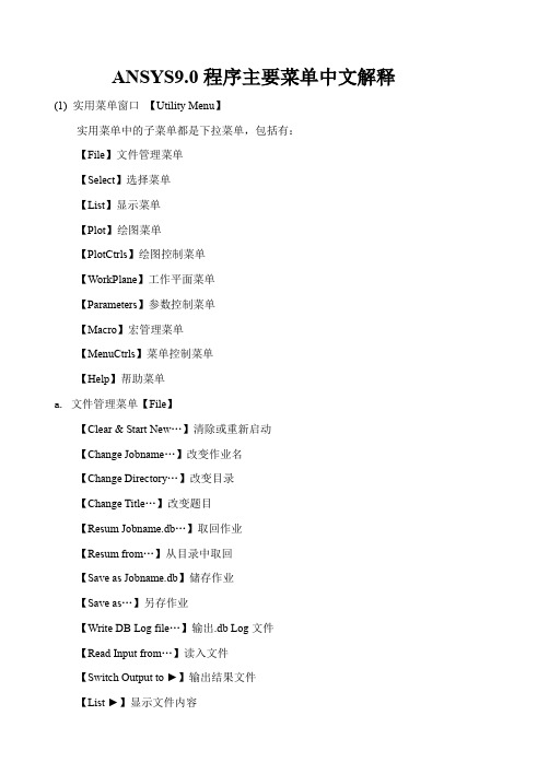
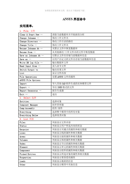
ANSYS9.0程序主要菜单中文解释(1) 实用菜单窗口【Utility Menu】实用菜单中的子菜单都是下拉菜单,包括有:【File】文件管理菜单【Select】选择菜单【List】显示菜单【Plot】绘图菜单【PlotCtrls】绘图控制菜单【WorkPlane】工作平面菜单【Parameters】参数控制菜单【Macro】宏管理菜单【MenuCtrls】菜单控制菜单【Help】帮助菜单a. 文件管理菜单【File】【Clear & Start New…】清除或重新启动【Change Jobname…】改变作业名【Change Directory…】改变目录【Change Title…】改变题目【Resum Jobname.db…】取回作业【Resum from…】从目录中取回【Save as Jobname.db】储存作业【Save as…】另存作业【Write DB Log file…】输出.db Log文件【Read Input from…】读入文件【Switch Output to ►】输出结果文件【List ►】显示文件内容【File Options ►】对文件进行重命名、删除和复制等操作【ANSYS File Options…】设定ANSYS文件的属性等【Import ►】导入其他CAD系统的文件【Export…】导出IGES格式的文件【Report Generator…】报告生成器【Exet…】退出b. 选择菜单【Select】【Entites…】选择实体【Component Manager…】组元管理【Comp/Assembly ►】选择组元和集合【Everything】重新激活整个模型【Everything Below ►】激活某类实体c.显示菜单【List】【File ►】显示文件内容【Status ►】显示选取内容的状态【Keypoint ►】显示关键点的属性和相关数据【Lines…】显示线的属性和相关数据【Areas】显示面的属性和相关数据【V olumes】显示体的属性和相关数据【Nodes…】显示节点的属性和相关数据【Elements ►】显示单元的属性和相关数据【Components】显示组元的属性和相关数据【Picked Entities +】显示选中的实体属性和相关数据【Properties ►】显示要查询内容的属性【Loads ►】显示载荷【Results ►】显示求解结果【Other ►】显示模型中其他的一些信息d. 绘图菜单【Plot】【Replot】重新绘制图形窗口中模型【Keypoints ►】在图形窗口中只绘制关键点【Lines】在图形窗口中只绘制线【Areas】在图形窗口中只绘制面【V olumns】在图形窗口中只绘制三维实体【Specified Entities ►】在图形窗口中只绘制指定的图元【Nodes】在图形窗口中只绘制节点【Elements】在图形窗口中只绘制单元【Layered Elements…】在图形窗口中只绘制分层的单元【Materials…】在图形窗口中只绘制材料属性【Data Tables…】在图形窗口中只绘制定义过的材料属性【Array paramentes…】在图形窗口中只绘制参数【Result ►】在图形窗口中只绘制求解结果【Multi-Plots】在图形窗口中只绘制所有图元【Components ►】在图形窗口中只绘制组元e. 绘图控制菜单【PlotCtrls】【Pan Zoom Rotate…】对模型进行移动、缩放和旋转【View Setings ►】模型观察视角的设置【Numbering…】图元编号显示控制【Symbols…】图元窗口中显示符号的控制【Style ►】模型显示风格控制【Font Controls ►】字体显示风格控制【Window Controls ►】图形窗口中的内容显示控制【Erase Options ►】在图形窗口中进行擦除操作【Animate ►】动画显示控制【Annotation ►】注释【Device Options…】设备选择【Redirect plots ►】更改绘图地址【Hard Copy ►】对屏幕进行硬拷贝【Save Plot ctrls…】储存绘图控制【Restore Plotctrls…】恢复绘图控制【Reset Plot ctrls】重新设置绘图控制【Capture Image…】扑捉图形窗口并以位图等文件保存【Restore Image…】恢复扑捉图形窗口【Write Metafile ►】输出材料数据【Multi-plot Controls…】多窗口绘图控制【Multi- Window Layout…】多窗口显示模型【Best Quality Image ►】最好质量扑捉图形窗口f.工作平面菜单【WorkPlane】【Display Working Plane】是否在图形窗口中显示工作平面【Show WP Status】显示工作平面状态【WP Setting…】工作平面参数设置【Offset WP by Increments…】对工作平面进行旋转【Offsets WP to ►】把工作平面移动到指定的图元位置【Align WP with ►】把工作平面按指定方向设置【Change Active CS to ►】更改当前激活坐标系【Change Display CS to ►】更改当前显示的坐标系【Local Coordinage Systems ►】局部坐标系的建立或删除等相关操作g.参数控制菜单【Parameters】h. 宏管理菜单【Macro】i. 菜单控制菜单【MenuCtrls】【Color Selection…】彩色选择【Font Selection…】字体选择【Update Toolbar】更改工具栏窗口【Edit Toolbar…】编辑工具栏窗口【Save Toolbar…】保存更改后的工具栏窗口【Restore Toolbar…】恢复工具栏窗口【Message Controls…】信息控制窗口【Save Menu Layout】保存更改后的菜单布局控制j.【Help】帮助菜单ANSYS的文档都在帮助菜单中,用到时可以查看。
- 1、下载文档前请自行甄别文档内容的完整性,平台不提供额外的编辑、内容补充、找答案等附加服务。
- 2、"仅部分预览"的文档,不可在线预览部分如存在完整性等问题,可反馈申请退款(可完整预览的文档不适用该条件!)。
- 3、如文档侵犯您的权益,请联系客服反馈,我们会尽快为您处理(人工客服工作时间:9:00-18:30)。
友情链接帮助联系方式留言首页Ansys案例Ansys技巧ansys新手I-deas Pro/Engineer UG学习Ansys专题Ansys 下载Ansys开发者论坛blog 搜索中心apdl二次开发[翻译]作者:面条| 发表日期:2005-3-16 | 繁体阅读|简体阅读|点击:670Chapter 4. APDL as a Macro Language4.1. What is an APDL Macro?Y ou can record a frequently used sequence of ANSYS commands in a macro file (these are sometimes called command files). Creating a macro enables you to, in effect, create your own custom ANSYS command. For example, calculating power loss due to eddy currents in a magnetic analysis would require a series of ANSYS commands in the postprocessor. By recording this set of commands in a macro, you have a new, single command that executes all of the commands required for that calculation. In addition to executing a series of ANSYS commands, a macro can call GUI functions or pass values into arguments.Y ou can also nest macros. That is, one macro can call a second macro, the second macro can call a third macro, and so on. Y ou can use up to 20 nesting levels, including any file switches caused by the ANSYS /INPUT command. After each nested macro executes, the ANSYS program returns control to the previous macro level.The following is a very simple example macro file. In this example, the macro creates a block with dimensions 4, 3, and, 2 and a sphere with a radius of 1. It then subtracts the sphere from one corner of the block./prep7/view,,-1,-2,-3block,,4,,3,,2sphere,1vsbv,1,2finishIf this macro were called mymacro.mac, you could execute this sequence of commands with the following single ANSYS command*use,mymacroor (because the extension is .mac)mymacroAlthough this is not a realistic macro, it does illustrate the principle.This chapter provides information on the various ways you can create, store, and execute macros.It also discusses the basic information you need to use APDL as a scripting language in creating macros.4.2. Creating a MacroY ou can create macros either within ANSYS itself or using your text editor of choice (such as emacs, vi, or wordpad). If your macro is fairly simple and short, creating it in ANSYS can be very convenient. If you are creating a longer, more complex macro or editing an existing macro then you will need a text editor. Also, using a text editor allows you to use a similar macro or ANSYS log file as the source for your macro.For any long, complex macro you should always consider either using a similar macro as a starting point or running the task interactively in ANSYS and using the resulting log file as the basis of your macro. Either method can greatly reduce the time and effort required to create a suitable macro.4.2.1. Macro File Naming ConventionsMacros are a sequence of ANSYS commands stored in a file. Macros should not have the same name as an existing ANSYS command; ANSYS will execute the internal command instead of the macro. The following naming restrictions apply to macro files:·The file name cannot exceed 32 characters.·The file name cannot begin with a numeral.·The file extension cannot contain more than eight characters (if you are executing the macro as if it were an ANSYS command it should have the extension .mac.)·The file name or extension cannot contain spaces.·The file name or extension cannot contain any characters prohibited by your file system and for portability should not contain any characters prohibited by either UNIX or Windows file systems. To ensure that you are not using the name of an ANSYS command, before creating a macro try running the file name that you wish to use as an ANSYS command. If ANSYS returns the message shown below, you will know that the command is not used in the current processor. Y ou should check the macro file name in each processor in which you plan to use the macro. (Y ou could also check if the macro file name matches any command listed in the online documentation; however, this method cannot locate the names of undocumented commands.)Using the .mac extension allows ANSYS to execute the macro as it would any internal command. Y ou should avoid using the extension .MAC because it is used for ANSYS internal macros.4.2.2. Macro Search PathBy default, ANSYS searches for a user macro file (.mac extension) in the following locations:1. The ANSYSnn/docu directory.2. The directory (or directories) designated by the ANSYS_MACROLIB environment variable (if defined) or the login (home) directory. This environment variable is documented in the ANSYS installation and configuration guide for your platform.3. The directory designated by the $HOME environment variable.4. The working directory.Y ou can place macros for your personal use in your home directory. Macros that should be available across your site should be placed in the ANSYSnn/docu directory or some commonly accessible directory that everyone can reference through the ANSYS_MACROLIB environment variable.·For Windows Me users: Y ou must designate the "home directory" and drive using environmentvariables, see the ANSYS Installation and Configuration Guide for Windows.·For Windows XP, 2000, and NT users: The "current directory" is the default directory (usually a network resource) set by administrators and you should ask your network administrator for its location. Y ou can use environment variables to create a local "home directory." The local home directory is checked after the default directory designated in your domain profile. See the ANSYS Installation and Configuration Guide for Windows for more information.4.2.3. Creating a Macro Within ANSYSY ou can create a macro by four methods from within ANSYS:·Issue the *CREA TE command in the input window. Parameter values are not resolved and parameter names are written to the file.·Use the *CFOPEN, *CFWRITE, and *CFCLOS commands. Parameter names are resolved to their current values and those values are written to the macro file.·Issue the /TEE command in the input window. This command writes a list of commands to a file at the same time that the commands are being executed. As the commands are executed in the current ANSYS session, parameter names are resolved to their current values. However, in the file that is created, parameter values are not resolved and parameter names are written instead. ·Choose the Utility Menu>Macro>Create Macro menu item. This method opens a dialog box that can be used as a simple, multi-line editor for creating macros. Parameter values are not resolved and parameter names are written to the file.The following sections detail each of these methods.4.2.3.1. Using *CREA TEIssuing *CREA TE redirects ANSYS commands entered in the command input window to the file designated by the command. All commands are redirected until you issue the *END command. If an existing file has the same name as the macro file name you specify, the ANSYS program overwrites the existing file.For example, suppose that you want to create a macro called matprop.mac, which automatically defines a set of material properties. The set of commands entered into the input window for this macro might look like this:*CREA TE,matprop,mac,macrosMP,EX,1,2.07E11MP,NUXY,1,.27MP,DENS,1,7835MP,KXX,1,42*ENDThe *CREA TE command takes arguments of the file name, the file extension, and the directory path (in this case, the macros directory is specified).When using *CREA TE, all parameters used in commands are written to the file (the currently assigned values for the parameter are not substituted).Y ou cannot use *CREA TE within a DO loop.4.2.3.2. Using *CFWRITEIf you wish to create a macro file in which current values are substituted for parameters you can use *CFWRITE. Unlike *CREA TE, the *CFWRITE command cannot specify a macro name; you must first specify the macro file with the *CFOPEN command. Only those ANSYS commands that are explicitly prefaced with a *CFWRITE command are then written to the designated file; allother commands entered in the command input window are executed. As with the *CREA TE command, *CFOPEN can specify a file name, a file extension, and a path. The following example writes a BLOCK command to the currently open macro file.*cfwrite,block,,a,,b,,cNote that parameters were used for arguments to the BLOCK command. The current value of those parameters (and not the parameter names) are written to the file. So, for this example, the line written to the macro file might be*cfwrite,block,,4,,2.5,,2To close the macro file, issue the *CFCLOS command.4.2.3.3. Using /TEEIssuing /TEE,NEW or /TEE,APPEND redirects ANSYS commands entered in the command input window to the file designated by the command at the same time that the commands are being executed. All commands are executed and redirected until you issue the /TEE,END command. If an existing file has the same name as the macro file name you specify with /TEE,NEW, the ANSYS program overwrites the existing file. To avoid this, use /TEE,APPEND instead.In addition to the Label argument (which can have a value of NEW, APPEND, or END), the /TEE command takes arguments of the file name, the file extension, and the directory path.As the commands are executed in the current ANSYS session, all parameter names are resolved to their current values. However, in the file that is created, parameter names are written (the currently assigned values for the parameter are not substituted). If your current parameter values are important, you can save the parameters to a file using the PARSA V command.For an example, see the description of the /TEE command in the ANSYS Commands Reference.4.2.3.4. Using Utility Menu>Macro>Create MacroChoosing this menu item opens an ANSYS dialog box that you can use as a simple editor for creating macros. Y ou cannot open and edit an existing macro with this facility; if you use the name of an existing macro as the arguments for the *CREA TE field, the existing file will be overwritten.4.3. Executing Macros and Macro LibrariesY ou can execute any macro file by issuing the *USE command. For example, to execute the macro called MYMACRO (no extension) residing somewhere in the macro search path, you would issue*use,mymacroIn this case, the macro takes no arguments. If instead the macro was called MYMACRO.MACRO and resided in /myaccount/macros, you could call it with*use,/myaccount/macros/mymacro.macroNote that the *USE command allows you to enter the path and extension along with the file name and that these are not entered as separate arguments.If a macro has a .mac file extension and resides in the search path, you can execute it as if it were an ANSYS command by simply entering it in the command input window. For example, to call mymacro.mac you could simply entermymacroY ou can also execute macros with a .mac extension through the Utility Menu>Macro>Execute Macro menu item.If the same macro takes arguments (see Passing Arguments to a Macro for more information about passing arguments to macros), then these can be entered on the command line as followsor*use,mymacro.mac,4,3,2,1.5The Utility Menu>Macro>Execute Macro menu item dialog provides fields for arguments. Executing macros contained in macro libraries is similar. Y ou must first specify the library file using the *ULIB command. For example, to specify that macros are in the mymacros.mlib file, which resides in the /myaccount/macros directory, you would issue the following command:*ulib,mymacros,mlib,/myaccount/macros/After selecting a macro library, you can execute any macro contained in the library by specifying it through the *USE command. As with macros contained in individual files, you can specify arguments as parameters in the *USE command.NoteY ou cannot use the *USE command to access macros not contained in the specified macro library file after issuing the *ULIB command.4.4. Local V ariablesAPDL provides two sets of specially named scalar parameters which are available for use as local variables. These consist of·A set of scalar parameters that provide a way of passing command line arguments to the macro. ·A set of scalar parameters that can be used within the macro. These provide a set of local variables that can be used to define values only within that macro.The following sections discuss both of these variable types in detail.4.4.1. Passing Arguments to a MacroThere are 19 scalar parameters that you can use to pass arguments from the macro execution command line to the macro. These scalar parameters can be reused with multiple macros; that is, their values are local to each macro. The parameters are named ARG1 through AR19 and they can be used for any of the following items:·Numbers·Alphanumeric character strings (up to eight characters enclosed in single quotes)·Numeric or character parameters·Parametric expressionsNoteY ou can pass only the values of parameters ARG1 through AR18 to a macro as arguments with the *USE command. If you create a macro that can be used as an ANSYS command (the macro files has a .mac extension), you can pass the values of parameters ARG1 through AR19 to the macro. For example, the following simple macro requires four arguments, ARG1, ARG2, ARG3, and ARG4:/prep7/view,,-1,-2,-3block,,arg1,,arg2,,arg3sphere,arg4vsbv,1,2finishTo execute this macro, a user might enter4.4.2. Local V ariables Within MacrosEach macro can have up to 79 scalar parameters used as local variables (AR20 through AR99). These parameters are completely local to the macro, and multiple macros can each have their own unique values assigned to these parameters. These parameters are not passed to macros called from macros (nested macros). They are passed to any files processed through a /INPUT command or a "do loop" processed within the macro.4.4.3. Local V ariables Outside of MacrosANSYS also has a similar set of ARG1 through AR99 scalar parameters that are local to an input file, and are not passed to any macros called by that input file. Thus, once a macro finishes and execution returns to an input file, the values of ARG1 through ARG99 revert to whatever values were defined within the input file.第四章宏命令4.1 什么是APDL宏命令?用户可以将一些经常使用的ANSYS命令记录在一个宏文件当中(有时也称为命令流文件)。