ETS6技术手册(12P)
(整理)ETS说明书.

松花江热电厂350MW×2机组汽轮机危急跳闸装置(ETS)说明书哈尔滨汽轮机厂自动控制有限公司二00九年七月十日汽轮机危急跳闸装置说明书编制:刘春华校对:审核:一、概述:ETS(EMERGENCY TRIP SYSTEM)是汽轮机危急跳闸系统的简称。
当汽轮机系统的一些指定参数超过其运行限制值时,ETS通过其AST电磁阀泄掉EH油, 关闭全部汽轮机蒸汽进汽阀门,紧急停机并记录眺机原因,从而保证了汽轮机安全运行,被监控的这些参数是:1. 汽轮机转速--超速跳闸;2. 推力轴承磨损--轴向位移大跳闸;3. 调节油压力低--低EH油压跳闸;4. 轴承润滑油压低--低润滑油压跳闸;5. 凝器器真空低--低真空跳闸;6. 轴承振动大--轴承振动大跳闸;7. 胀差大--胀差大跳闸;8. DEH110%-- DEH110%跳闸;9.发电机主保护--发电机主保护跳闸; (电厂选用)10.MFT---锅炉保护跳闸; (电厂选用)11.高排温度高—高排温度高跳闸; (电厂选用)12.高排压力高—高排压力高跳闸; (电厂选用)13.轴承金属温度高—轴承温度高跳闸;(电厂选用)14.远控手动跳机 (电厂选用)15.备用1 (电厂选用)16.备用2 (电厂选用)17.备用3 (电厂选用)18.备用4 (电厂选用)19.备用5 (电厂选用)20.备用6 (电厂选用)21.备用7 (电厂选用)22.备用8 (电厂选用)23.备用9 (电厂选用)24.备用10 (电厂选用)二、组成:1.控制柜1面,硬件采用与DEH一体化的ABB设备2.危急跳闸控制块;3.三个试验块(LP、LBO、LV)。
4.操作界面为DEH画面中的一部分。
5.系统机柜中DPU采用双冗余BRC300控制器,通过数字IO卡件进行信号的输入和输出。
三、跳闸块工作原理:跳闸块安装在前箱的右侧,块上共有6个电磁阀,2个OPC电磁阀是220VDC,常闭电磁阀;4个AST电磁阀是220VDC,常开阀。
XT6服务屏障安装指南说明书
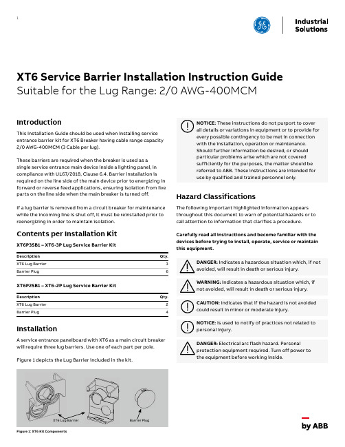
1XT6 Service Barrier Installation Instruction Guide Suitable for the Lug Range: 2/0 AWG-400MCMIntroductionThis Installation Guide should be used when installing service entrance barrier kit for XT6 Breaker having cable range capacity 2/0 AWG-400MCM (3 Cable per lug).These barriers are required when the breaker is used as a single service entrance main device inside a lighting panel, in compliance with UL67/2018, Clause 6.4. Barrier installation is required on the line side of the main device prior to energizing in forward or reverse feed applications, ensuring isolation from live parts on the line side when the main breaker is turned off.If a lug barrier is removed from a circuit breaker for maintenance while the incoming line is shut off, it must be reinstalled prior to reenergizing in order to maintain isolation.Contents per Installation KitXT6P3SB1 – XT6-3P Lug Service Barrier KitDescription Qty.XT6 Lug Barrier 3Barrier Plug6XT6P2SB1 – XT6-2P Lug Service Barrier KitDescription Qty.XT6 Lug Barrier 2Barrier Plug4InstallationA service entrance panelboard with XT6 as a main circuit breaker will require three lug barriers. Use one of each part per pole.Figure 1 depicts the Lug Barrier included in the kit.Figure 1: XT6 Kit ComponentsHazard ClassificationsThe following important highlighted information appears throughout this document to warn of potential hazards or to call attention to information that clarifies a procedure.Carefully read all instructions and become familiar with the devices before trying to install, operate, service or maintain this equipment.XT6 Lug BarrierBarrier Plug2X T6 S E RV I CE B A R R I E R I N S TA LL ATI O N I N S TR U C TI O N S - LU G R A N G E 2/0 AWG -400M CM R A N G EKit Installation StepsTo install Finger Safe Barrier follow steps provided under this installation procedure.This Finger Safe Barrier must be installed prior to the wire connection to the circuit breaker. Item A Terminal Cover Screw Item B Terminal Cover Item C Lug Barrier Item DBarrier PlugFigure 2: Remove the Item A and B from Circuit BreakerStep 1: Remove Item A and B Step 2: A ssemble Item C, ensure the snap fit as shown inFigure 3Step 3: Assemble Item D (Mandatory for unutilized port)Step 4: Assemble Item B and AFigure 3: Assemble the Item C, snap fit at 3 places as shown in viewFigure 4: Assemble Item DFigure 5: Assemble the Item B and A on Circuit Breaker(1, 2, 3 are snap fit location)X T6 S E RV I CE B A R R I E R I N S TA LL ATI O N I N S TR U C TI O N S - LU G R A N G E 2/0 AWG -400M CM R A N G E3Cable InstallationBefore installing the cable, remove necessary knock outs from the terminal cover as shown in Figure 7.The wires must be stripped to the correct length to maintain isolation. After stripping the wires to the required length, the wires can be installed as shown in Figure 8. The lug barrier must be correctly installed to maintain electrical isolation from accidental contact. Torque the wires according to the torque specification on the breaker.Table 1: Shows the allowable wire sizes for the barrier.Lug RangeStrip Length 800 A2/0 AWG to 400MCM Cu/Al (3 Cable per Lug)1.22"Figure 8: Maximum Wire Strip LengthFigure 7: Removing knock outs on terminal cover after wiring installationFigure 6: After assembly of Item A to D4X T6 S E RV I CE B A R R I E R I N S TA LL ATI O N I N S TR U C TI O N S - LU G R A N G E 2/0 AWG -400M CM R A N G E1T Q C 173000E 0039,D E H 0033142,M A R 2020—ABB Inc.305 Gregson Drive Cary, NC 27511©Copyright 2020 ABB. All rights reserved.Information provided is subject to change without notice. Please verify all details with ABB. All values are design or typical values when measured under laboratory conditions, and ABB makes no warranty or guarantee, express or implied, that such performance will be obtained under end-use conditions.GE is a registered trademark used under license from General Electric company.。
贝利摩6路控制阀技术数据表说明书
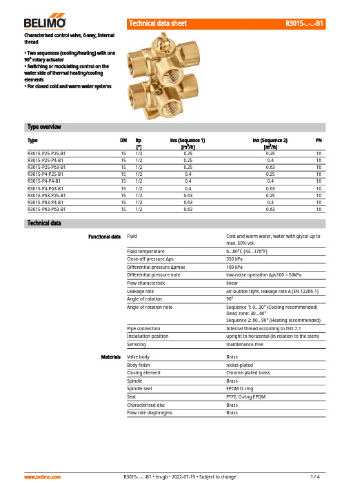
R3015-..-..-B1Characterised control valve, 6-way, Internalthread• Two sequences (cooling/heating) with one 90° rotary actuator• Switching or modulating control on the water side of thermal heating/cooling elements• For closed cold and warm water systemsType overviewTypeDN Rp ["]kvs (Sequence 1)[m³/h]kvs (Sequence 2)[m³/h]PN R3015-P25-P25-B1151/20.250.2516R3015-P25-P4-B1151/20.250.416R3015-P25-P63-B1151/20.250.6316R3015-P4-P25-B1151/20.40.2516R3015-P4-P4-B1151/20.40.416R3015-P4-P63-B1151/20.40.6316R3015-P63-P25-B1151/20.630.2516R3015-P63-P4-B1151/20.630.416R3015-P63-P63-B1151/20.630.6316Technical dataFunctional dataFluidCold and warm water, water with glycol up to max. 50% vol.Fluid temperature 6...80°C [43...176°F]Close-off pressure ∆ps 350 kPa Differential pressure Δpmax 100 kPaDifferential pressure note low-noise operation Δpv100 < 50kPa Flow characteristic linearLeakage rate air-bubble tight, leakage rate A (EN 12266-1)Angle of rotation 90°Angle of rotation noteSequence 1: 0...30° (Cooling recommended)Dead zone: 30...60°Sequence 2: 60...90° (Heating recommended)Pipe connection Internal thread according to ISO 7-1Installation position upright to horizontal (in relation to the stem)Servicingmaintenance-free MaterialsValve body Brass Body finish nickel-plated Closing element Chrome-plated brass Spindle Brass Spindle seal EPDM O-ring SeatPTFE, O-ring EPDM Characterised disc Brass Flow rate diaphragmsBrassR3015-..-..-B1•••••Mode of operationPressure compensationRecommended installation positionsWater quality requirements Safety notesThe valve has been designed for use in stationary heating, ventilation and air-conditioning systems and must not be used outside the specified field of application, especially in aircraft or in any other airborne means of transport.Only authorised specialists may carry out installation. All applicable legal or institutional installation regulations must be complied during installation.The valve does not contain any parts that can be replaced or repaired by the user.The valve may not be disposed of as household refuse. All locally valid regulations and requirements must be observed.When determining the flow rate characteristic of controlled devices, the recognised directives must be observed.Product featuresThe 6-way characterised control valve is adjusted by a rotary actuator. The actuator is connected by a modulating control system or a bus signal and moves the ball of the ball valve to the position dictated by the control signal.If the valve is adjusted in the clockwise direction (till the end stop), e.g. the cooling sequence is completely enabled; if the valve is adjusted in the counter-clockwise direction (90°), e.g. the heating sequence is completely enabled.In cases of combined heating/cooling control elements, the fluid remains in the control element when in the closed position (no heating or cooling). The pressure of the enclosed fluid can rise or fall due to changes in fluid temperature caused by the ambient temperature. The 6-way characterised control valves have an integrated pressure relief function for the purpose of compensating for such pressure changes.The pressure relief function is active in the closed position (45°) of the valve; reliable separation of Sequences 1 and 2 continues. For additional information, consult the notes for project planning for the 6-way characterised control valve.AccessoriesMechanical accessoriesDescriptionType Elbow 90° male/female DN 15 Rp 1/2, R 1/2, Set of 2 pcs.P2P15PE-1GE Fixing bracket for 6-way valve DN 15/20ZR-004Pipe connector for ball valve DN 15ZR2315Installation notesThe ball valve can be installed upright to horizontal. The ball valve may not be installed in ahanging position, i.e. with the spindle pointing downwards.The water quality requirements specified in VDI 2035 must be adhered to.Belimo valves are regulating devices. For the valves to function correctly in the long term, they must be kept free from particle debris (e.g. welding beads during installation work). The installation of a suitable strainer is recommended.R3015-..-..-B1ServicingFlow directionValve characteristic curve Using an additional flow limiterBall valves and rotary actuators are maintenance-free.Before any service work on the control element is carried out, it is essential to isolate the rotary actuator from the power supply (by unplugging the electrical cable if necessary). Any pumps in the part of the piping system concerned must also be switched off and the appropriate slide valves closed (allow all components to cool down first if necessary and always reduce the system pressure to ambient pressure level).The system must not be returned to service until the ball valve and the rotary actuator have been correctly reassembled in accordance with the instructions and the pipeline has been refilled by professionally trained personnel.The flow direction must be observed. The position of the ball can be identified from the L-marking on the spindle.The lower diagram shows the valve characteristic curve in relation to the ball position.When using additional flow limiting valves (e.g. PIQCV C2..QP(T)-.. with manual flow rate setting) or an additional pressure-independent control valve (e.g. motorised PIQCV) at the system level, it is not necessary to use the flow characterised disc in the 6-way valve in the system to reduce the kvs value.R3015-..-..-B1 DimensionsDimensional drawingsThe actuator dimensions can be found on the respective actuator data sheet.Further documentation• The complete product range for water applications• Data sheets for actuators• Installation instructions for actuators and/or ball valves• Notes for project planning for 6-way characterised control valves。
P-S-6-S-6中文资料
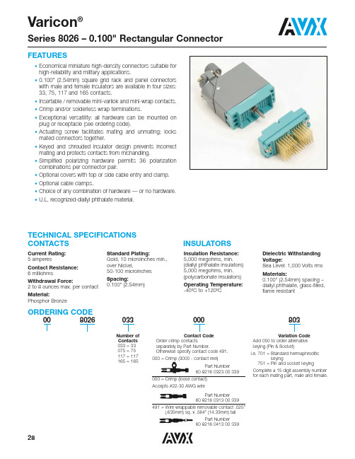
FEATURES•Economical miniature high-density connectors suitable for high-reliability and military applications.•0.100" (2.54mm) square grid rack and panel connectors with male and female insulators are available in four sizes:33, 75, 117 and 165 contacts.•Insertable / removable mini-varilok and mini-wrap contacts.•Crimp and/or solderless wrap terminations.•E xceptional versatility: all hardware can be mounted on plug or receptacle (see ordering code).•Actuating screw facilitates mating and unmating; locks mated connectors together.•Keyed and shrouded insulator design prevents incorrect mating and protects contacts from mishandling.•Simplified polarizing hardware permits 36 polarization combinations per connector pair.•Optional covers with top or side cable entry and clamp.•Optional cable clamps.•Choice of any combination of hardware — or no hardware.•U.L. recognized-diallyl phthalate material.Current Rating:5 amperesContact Resistance:6 milliohmsWithdrawal Force:2 to 8 ounces max. per contact Material:Phosphor BronzeStandard Plating:Gold, 10 microinches min., over Nickel,50-100 microinches Spacing:0.100" (2.54mm)TECHNICAL SPECIFICATIONS CONTACTSINSULATORSInsulation Resistance:5,000 megohms, min. (diallyl phthalate insulators)5,000 megohms, min. (polycarbonate insulators)Operating Temperature:-40ºC to +120ºCDielectric Withstanding Voltage:Sea Level: 1,000 Volts rms Materials:0.100" (2.54mm) spacing – diallyl phthalate, glass-filled, flame resistantORDERING CODE008026033Number of Contacts 033 = 33075 = 75 117 = 117165 = 165000Contact CodeOrder crimp contactsseparately by Part Number.Otherwise specify contact code 491.000 = Crimp (3000 - contact reel)Part Number 60 8216 0323 00 339000 = Crimp (loose contact)Accepts #22-30 AWG wirePart Number 60 8216 0313 00 339491 = Wire wrappable removable contact .025"(.635mm) sq. x .564" (14.33mm) tailPart Number 60 8216 0413 00 339803Variation CodeAdd 050 to order alternative keying (Pin & Socket)i.e. 701 = Standard hermaphroditickeying751 = Pin and socket keyingComplete a 15 digit assembly number for each mating part, male and female.VARIATION CODESVariation Code No.Insulator Cover Cover Cable Actuating FixedKeying Body Without Small Large EntranceNut Screw Hardware TypeCover Clamp Clamp501——No Yes No Yes 502——No Yes No No 503——No No Yes Yes 504——No No Yes No —505513Top Yes No Yes —506514Side Yes No Yes Male—507515Top Yes No No (Exposed —508516Side Yes No No Contacts)—509517Top No Yes Yes —510518Side No Yes Yes —511519Top No Yes No —512520Side No Yes No 601——No No Yes Yes 602——No No Yes No 603——No Yes No Yes 604——No Yes No No —605613Top No Yes Yes —606614Side No Yes Yes Female —607615Top No Yes No (Recessed —608616Side No Yes No Contacts)—609617Top Yes No Yes —610618Side Yes No Yes —611619Top Yes No No —612620Side Yes No NoT able 4Varicon ®Series 8026 – 0.100" Rectangular Connector33 CONTACTSFemale Plug (Recessed Contacts)For variation code number See Table 1See Table 2Page 29Page 2975 CONTACTSFemale Plug (Recessed Contacts)For variation code number See Table 3See Table 4Page 29Page 29EE E E E E E ESERIES 8026 COVER CROSS REFERENCE. FOR DETAILS SEE PAGE 21Varicon®Series 8026 – 0.100" Rectangular ConnectorPOLARIZATION / KEYING ALTERNATIVE KEYINGEXAMPLE (PIN & SOCKET)PInsulator Body TypeP = Male, R = FemaleLSLeft Side Pin5Left Side Pin Position1 through 6RSRight Side Pin Right Side Pin Position1 through 6NOTE:Same size of pin and socket keying hardware are usedon all existing 8026 connectors (33, 75, 117, 165) – both sides POLARIZATION CODEPolarizing pins, when desired, are factory set in position #1.Customer can reset as shown below, use tool No. 06 198902. To order factory settings other than position #1, fill outthe “Polarizing Code” below and submit it along with thecompleted connector ordering code.。
温度控制器ETC-H6功能表V1[1].2_100720
![温度控制器ETC-H6功能表V1[1].2_100720](https://img.taocdn.com/s3/m/eed9d980b9d528ea81c77993.png)
一、工作条件:1、工作电压:220VAC±10% 50/60Hz;2、继电器触点输出容量:16A/220VAC,额定工作电流8A/220VAC;3、工作环境温度:0℃~50℃;工作相对湿度:20%~85% 不可结露;4、存储温度:-5℃~50℃;二、规格尺寸:1、整机尺寸:长77×宽34.5×深58(毫米);2、安装尺寸:长71×宽29 (毫米)3、传感器线长:2.5米(含探头长度)。
三、功能及技术参数:1、测量温度范围:-50℃~85℃;显示分辨率:0.1℃;2、测温精度:0℃~15℃:±0.5℃;其余范围:±1℃;3、备有后备电源,当外部电源断开后,蜂鸣器断续间歇鸣叫2分钟,在电池连续充电满10小时的条件下外部断电后控制器继续显示温度16小时;4、温控器设有特殊模式和非特殊模式,在这两种模式下,分别设有A模式和b模式,A模式专用冰衬,b模式为一般模式;5、一路警音报警输出(蜂鸣器);6、柜温传感器输入,传感器类型:NTC(10KΩ/25℃,B值3435K);7、LCD显示,外部供电时带背光显示;四、操作及显示面板FN按键标示;SET按键标示;▲按键标示;▼按键标示;制冷标示:当压缩机工作时,此符号显示;电源标示:当控制器的外部电源接通时,此符号显示;锁定标示:当控制器锁定时,此符号显示;报警标示:当控制器处于报警状态时,此符号闪烁以提醒用户;除霜标示:当控制器处于化霜状态时,此符号显示;五、控制器参数及操作:控制器在正常情况下显示测量的温度,当传感器故障时显示“Err”,传感器高于85o C时显示“EHi”,低于-50o C时显示“ELo”。
设置控制温度在正常运行状态下,解锁后,按SET键大于3秒,显示屏显示当前的控制温度St设定值;用▲键或者▼键来增加或者减小数值,一直到达期望值;再按SET键确认新的数值,存储修改的参数数值并且退出参数设置程序。
费斯托 MSE6-C2M 能效模块 说明书

FESTO MSE6 能源效率模块说明书
Energy effi ciency modules MSE6Reduce your CO 2 emissions!• A unique solution, the first of its kind on the market • Monitoring the compressed air consumption and supply • Automatic detection of leakages• No negative impact on plant and system availability • Can be expanded in the CPX system• Quick return on investmentHighlightsIntelligent use of energy The energy effi ciency module MSE6-C2M combines pressure regulator, on/off valve, sensors and fi eldbus communication in one unit. It monitors the compressed air consumption, shuts off the compressed air after production has stopped for a certain amount of time, and prevents the system pressure from falling below a specifi c stand-by pressure level.Ready for Industry 4.0With the modules -C2M and -E2M from the MSE6 series condition monitoring takes place via fi eldbuses or PROFINET and measured values such as pressure and fl ow rate areprovided via the PLC or the cloud. The additional module MSE6-D2M is an effi cient extension of the -C2M via a second supply string.Greater process reliabilityAll modules of the MSE6 series are connected to the machine control system, and detect and report leakages that occur after the system has been shut off.Where previously condition monitoring and control in compressed air systems was limited to gathering and analysing measurement data, consumption can now be automatically reduced by actively intervening in the supply. Thanks to patented technology from Festo, you can save up to 3.2 t of CO 2, and hundreds of euros in operating costs per year.2Energy efficiency modules MSE6 – Subject to change – 2020/02Thinking ahead about compressed air supplyMSE6-C2M MSE6-D2MNew standards for clean productionThe topics of resource conservation and energy effi ciency, galvanised by the Paris Climate ProtectionAgreement on CO 2 reduction, are also playing an increasingly important role in industrial automation. Leading companies have already defi ned clear CO 2 targets for their products. Implementing these requires machines that achieve signifi cant energy savings compared to previous models. That is precisely why Festo offers the MSE6 series, a solution that is unique on the market.Energy effi ciency modules MSE6 at a glance2020/02 – Subject to change – Energy efficiency modules MSE63MSE6-E2MWhether with existing or new systems, there are implementation options in almost every applicationEnergy efficiency modules MSE6 can be installed in existing or new systems, wherever the supply of compressed air is to be monitored and controlled.Detecting stand-by states, automatic shut-off or stand-by pressure controlAfter entering machine-specific parameters, the modules recognise when a system is operating or idling. By shutting off the compressed air supply, air cannot be consumed unnecessarily and will not continue to be supplied to any leaks in the machine. Instead, the MSE6-C2M can maintain the output pressure at a previously defined stand-by pressure so that system availability is not impaired.Leakage measurementAfter shutting off the compressed air supply, the system can be checked for pressure leaks. The user therefore first needs to determine if the rate of pressure drops are too high or untypical. By reporting such pressure drops to the PLC, the energy efficiency modules trigger a warning, such as “Possible leakage in the machine. Check required”. This information can then be used by maintenance staff to plan and carry out a service.Condition monitoringEnergy efficiency modules MSE6 can be fully integrated into the machine control system via fieldbus nodes in order to cyclically exchange important energy consumption andavailability data for the system. This data can be transferred from the MSE6-E2M to the cloud via the Festo IoT gateway CPX-IOT, and thus recorded and analysed as long-term measured values.4Energy efficiency modules MSE6 – Subject to change – 2020/02* Assumption: 760 h repair/maintenance ** Depending on the type of leakage:based on a purely statistical worst-case scenario (hole in the tubing) = 70%Return on investment after only 1 to 1½ years*Let’s assume that a machine is operational on 250 days per year based on two shifts and has a compressed air consumption of 2,000 l/min at 6 bar and a leakage rate of 10%. If the compressed air is not shut off during the 4,000 hours of non-production time, 48,000 Nm³ is simply lost. This would be an expensive luxury that would cost you €912 and 3.2 t of CO 2 emissions. On the other hand, by simply reducing the pressure from 6 bar to 2.5 bar, you can save as much as €640 and 2.2 t in CO 2 emissions. And since the energy efficiency modulesincorporate additional functions such as those of the classic pressure regulator MS6-LR, on/off valve MS6-EE, pressuresensors SPAU and flow rate sensors SFAM, the amortisation period is further reduced. Especially if you consider the costs of a cyclical manualleakage detection. The bottom line is that a more conscious use of compressed air pays for itself in less than 1 to 1½ years.Plenty of savings potential* Please note: the following sample calculations are based on realistic assumptions and conditions. The values for your systems may differ and therefore the validity of this information cannot be guaranteed.Possible savings with the module MSE6-C2M*** 1 kWh of electricity produces 0.5 kg CO 2.These figures apply to Germany and may vary in other countries. Source for 2015 figures: German Federal Environment Agency (https://www.umweltbundesamt.de/themen/klima-energie/energieversorgung/strom-waermeversorgung-in-zahlen#Strommix)Possible savings with the modules MSE6-E2M and MSE6-D2M* Assumption: 760 h repair/maintenance ** Depending on the type of leakage *** 1 kWh of electricity produces 0.5 kg CO2.These figures apply to Germany and may vary in other countries. Source for 2015 figures: German Federal Environment Agency (https://www.umweltbundesamt.de/themen/klima-energie/ energieversorgung/strom-waermeversorgung-in-zahlen#Strommix)2020/02 – Subject to change – Energy efficiency modules MSE656Energy efficiency modules MSE6 – Subject to change – 2020/02Proportional pressure regulatorElectric on/off valve(normally open)Integrated pressure sensor (P2)MS pressure gauge (P2)Mounting bracketElectronics housingDC 24V supplyFlow rate sensorInterface for integration into the Festo MS6 seriesStatus display(status device and IOs)Profi net bus node CPX FB342 DI (M12) / 2 DO (M12) /CPX extension port (optional)Energy effi ciency module MSE6-C2MReducing the pressure in stand-by modeP1P22020/02 – Subject to change – Energy effi ciency modules MSE67Control functions• Adjustable regulated output pressure• Automatic pressure reduction without exhausting the system during downtimes• Detecting leaks by evaluating the pressure drop in stand-by mode• Adjustable pressure increase (soft-start)• Digital inputs and outputsProcess monitoring • Flow rate• Air consumption • Output pressure • Change in pressureModularity• Can be combined in the MS modular system • Compatible with CPX (system bus extension)Benefi ts• Optimised consumptionthrough adjustable, regulated output pressure• Avoiding or reducingcompressed air consumption during system downtime • Leakage detection• Gathering and preparingpneumatic measured variables for process monitoring • Connecting externalcomponents via electrical inputs and outputs • Fieldbus networkingOperation in automatic mode Flow rateFlow rate limitNormal Wait Stand-by NormalPressure P2Power-saving modeTimeAutomatic shut-offRestarting productionLeakage detectedProduction stop detected−60 ... 75%Soft-startHolding pressure regulationNormal operating pressure Stand-by pressureExample of regulating the holding pressure from 6 bar to 2.5 bar, depending on the type of leakage: based on a purely statistical worst-case scenario (hole in tubing) = 60%8Energy efficiency modules MSE6 – Subject to change – 2020/02Status indicatorsFieldbus nodeProfibus, Profinet, EtherCAT,EthernetIPStand-alone solution for shutting off the compressed airIntegrated pressure sensor (P2)Flow rate sensorPower supply2020/02 – Subject to change – Energy effi ciency modules MSE69Restarting productionFlow rate sensorElectric on/off valve(normally open)Integrated pressure sensor (P2)MS pressure gauge (P2)Mounting bracketElectronics housingCPX extension port for connecting to theFesto MSE6-C2M or CPXStatus display deviceInterface for integration into the Festo MS6 seriesBenefi ts• Avoiding compressed air consumption during system downtime• Leakage detection• Gathering and preparingpneumatic measured variables for process monitoring • Connecting externalcomponents via electrical inputs and outputs • Fieldbus networkingExtended solution for shutting off the compressed airFlow rateFlow rate limitNormal Wait Stand-by NormalPressure P2Power-saving modeTimeLeakage detectedProduction stop detectedOperation in automatic mode P1P2Automatic shut-offNo compressed air consumption10Energy effi ciency modules MSE6 – Subject to change – 2020/02Shaping the future with a leading technological edgeHow to distinguish yourself as a “green company ”The energy effi ciency modules MSE6 are particularly interesting for applications in the automotive industry, in machine tools, in food and packaging systems, in general machine building and in process technology. But they can also contribute to energy optimisation in virtually every industry that has a high degree ofautomation, whether it is integrated in or separate from an existing service air preparation unit.Perfect for supplying compressed air to cells • Pressure control via fi eldbus • Continuous pressure and fl ow measurement• Automatic holding pressure reduction during non-production times prevents pneumatic clamps from dropping• Automatic leakage detection • Connecting additional devices (IOs) to the hall or robot installation plate• Data provider for condition monitoring and process data acquisition systemMSE6-C2M/D2M in the car body shop in the automotive industry2020/02 – Subject to change – Energy effi ciency modules MSE611Perfect for supplyingcompressed air to machine tools • Pressure control via fi eldbus • Continuous pressure and fl ow measurement• Automatic reduction of the stand-by pressure during non-production times• Guaranteed supply of sealing air during stand-by• Automatic leakage detection • Mounting additional devices (IOs) on the installation plate reduces the number of fi eldbus nodes• Data provider for condition monitoring and process data acquisition system as well asapps and servicesLock-out/tag-out: lockable manual on/off valve MS6-EM1 with exhaust functionLow pressure drop for maximum energy effi ciency: high-fl ow MS9-LF fi lter in size 9Networkable energy effi ciency module MSE6-C2M for pressure control and measurementSoft-start/quick exhaust valve MS6-SV-EMSE6-C2M in machine toolsMSE6 in an air preparation environment12Energy effi ciency modules MSE6 – Subject to change – 2020/02Clever combination for comprehensive conceptsThe right product at the right timeVirtually all large companies across all industry sectors are setting themselves ambitious energy effi ciency targets. This is precisely where the Festo MSE6 series is the perfect solution, as it demonstrates how products that are available immediately can create signifi cant added value in digitalisation and energy effi ciency. Being able to expand the MSE6-C2M-...-M-...with an MSE6-D2M or a CPX IO terminal saves you fi eldbus nodes. This enables you to control sub-functions such as mounting plates for system power supply with only one fi eldbus connection. The network topology of your system remains lean and clear.Application 1: combination of MSE6-C2M and MSE6-D2MMSE6-D2MBenefi ts• Energy effi ciency function for two separate compressed air networks• Leakage detection • Only one fi eldbus connection required• Direct integration of 2DI/2DO, e.g. for controlling external valves and sensor technology• Process monitoring• Integrated pressure and fl ow measurement• Fieldbus controlled pressure regulation with automatic stand-by pressure reductionvia MSE6-C2MMSE6-C2M Profi netDevice/unit Festo system bus2 DI/2 DO CloudPLC2020/02 – Subject to change – Energy effi ciency modules MSE613Application 2: combining MSE6-C2M with CPX terminalBenefi ts• Energy effi ciency function with pressure regulation • Leakage detection • Only one fi eldbus connection required• Direct integration of 2DI/2DO, e.g. for controlling the valves and the sensor technology• Additional DI/DO/AI/AO can be integrated on a CPX IO terminal (max. 3 modules – please observe the system limits of the CPX)• Process monitoring with leakage detection• Integrated pressure and fl ow measurement• Fieldbus-controlled pressure regulation with automatic stand-by pressure reductionApplication 3: combining CPX terminal with connected MSE6-D2M on a mounting plateBenefi ts• Energy effi ciency function • Connection to CPX terminal with CPX extension (please observe the system limits of the CPX)• Process monitoring with leakage detection• Integrated pressure and fl ow measurement• Automatic detection of the end of production and subsequent shut-off of the compressed air supply • Cost-effi cient solution with only one fieldbus nodeMSE6-C2MProfi netDevice/unit Festo system bus2 DI/2 DO CPX-IO terminalAvailable modules• CPX-4DI (24VDC, PNP)• CPX-8DI (24VDC, PNP)• CPX-4DO(24VDC, 0,5A, PNP)• CPX-8DO(24VDC, 0,5A, PNP• CPX-8DI/8DO (24VDC, 0,25A, PNP)• CPX-4AI-U-I • CPX-2AO-U-IProfinetCPX-IO terminalMSE6-D2MFesto system busCloudPLCCloudPLC14Energy efficiency modules MSE6 – Subject to change – 2020/02Easy and consistent implementation of digitalisation with the MSE6What’s the compressed air consumption and the system status? Completely transparent!Thanks to cloud-based analysis with the Festo energy effi ciency module MSE6-E2M and the Festo Dashboard you can now fi nd out exactly how your system is doing.Innovative cloud solutionModern web-based data analysis ensures greater transparency and improves the availability of the pneumatics in your system. You will immediately notice the energy and CO 2 savings that are achieved when using the Festo energy effi ciency module.Not only does this save you money, but it can also help your company to answer any questions about certifi cation, e.g. by providing information on the CO 2 footprint of the products, sustainability and so on.Predictive maintenance The new analysis options support the early detection of changes in the system. As a result, service can be scheduled to take place outside ofproduction hours. This reduces unplanned downtime and unproductive time as well as cuts costs.15Festo DashboardsFesto’s cloud solution supports you as a customer over the entire life cycle of your system – and increases your productivity, e.g. through more effi cient engineering and various value-added services. The fi rst step is to access the condition monitoring dashboard for your Festo devices.Flexible widgets for a wide range of evaluationsYou can analyse limit values for any periods within a given year. The energy savings that have been automatically made during idle times are clear to see.IoT gateway CPX-IOT hardware for unlimited communication The industrial Internet of Things gateway in the CPX module format collects information about Festo devices and their statuses via Ethernet using a standardised communication protocol. It then sends this information to the cloud via the second Ethernet port. State-of-the-art IT security mechanisms keep the data completely secure.Flow rate sensor Total values overdefi ned periods • New cloud technology with web interface without the need for additional software• Cloud-based database forfast and effi cient analysis of long-term measured values2020/02 – Subject to change – Energy effi ciency modules MSE6Energy effi ciency modules MSE6Everything that distinguishes a classic win-win situationEveryone benefi ts from intelligent solutions that make processes even more effi cient thanks to a competitive advantage. A welcome effect is that anyone who drives automation with Festo is also at the forefront of environmental awareness. See for yourself!Advantages for OEMs in machine building l You have the opportunity to sell energy effi ciency packagesl You can offer after-sales services in case of leakagel You will distinguish yourself as a leader in innovation Benefi ts for corporate end usersl You lower your manufacturing costs by reducing your compressed air consumption l You considerably reduce yourCO2 footprintl You will distinguish yourself as a“green company”Overview: MSE6-C2M/-D2M/-E2M technical dataMSE6-C2M-…MSE6-C2M-…-M-…MSE6-D2M MSE6-E2MMeasurement data acquisition Flow measurement•Pressure measurement p2•Measurement data calculation (derived measurement data)Consumption measurement•Change in pressure•Pressure regulation and control functions • Shut-off function: automatic shut-off in theevent of a permanent fl ow rate shortfall(energy effi ciency function)• User-controlled pressurisation/exhausting•• Pressure regulation minus holdingpressure• Working pressure control•.Connections Electrical inputs2x DI (24V).Electrical outputs1x DO (24V 0.5A)1x DO (24V 0.5A) (together max. 1A).CPX extension.••.24V supply• (Push-pull AIDA).• (M18) Display LEDs (status indication)•(•) Pressure gauge p2•. Fieldbus connection Profi bus / Profi net / EtherCAT / Ethernet IP. / Profi net / . / .• / • / • / •Characteristic values – pneumatics Operating pressure P1 5.0 … 11.0 bar 3.5 … 13.0 bar 4.0 … 10.0 barOutput pressure P2 2.5 … 10.0 bar 3.5 … 13.0 bar 4.0 … 10.0 bar Standard nominal fl ow rate (qnN)5,000 L/min4,500 L/min4,500 L/min135999en22/2–Errorsandomissionsexcepted。
ETS6技术手册(12P)
R22
1.00
1.04
1.10
1.16
1.20
1.25
1.30
1.35
1.41
1.45
1.50
R410A
1.00
1.06
1.14
1.21
1.28
1.34
1.40
1.47
1.53
1.58
1.65
R407C
1.00
1.06
1.14
1.20
1.28
1.34
1.40
1.47
1.53
1.60
1.66
R134a
1.00
1.06
1.14
1.19
1.26
1.32
1.38
1.45
1.50
1.56
1.63
R404A/R507 1.00
1.07
1.18
1.29
1.38
1.47
1.56
1.65
1.75
1.82
1.91
技术手册
电子膨胀阀,ETS 6
额定能力 (kW)
冷凝温度
(°C)
10
5
ETS 6 -10
蒸发温度 (°C)
30,000 个全冲程循环测试,其中包括每次关闭时的 20 个过盈脉冲。 相对湿度不超过 95% 永磁型直动步进电机 1-2 相 JST XHP-6 与 JST XHP-5 最小 30pps(每秒脉冲)至最大 90pps,建议为 31.3pps 0 到 480 个脉冲,无需保持电源(注: 请勿施加多于 520 个脉冲) 如:16 sec @ 30 pps, 6 sec @ 80 pps 线圈位于上方,阀门/线圈总成位于纵轴 ±15° 以内 在使用液管电磁阀的情况下,安装时应确保其不会在 ETS 6 阀门内产生液锤 115°C (239° F)
SC-ISOSLICE-6用户手册说明书
Address Switch 8 7 6 5 4 3 2 1
Action add 1 add 2 add 4 add 8 add 16 add 32 add 64 is not used
LED Address
Channel 1 2 3 4 5 6 7 8
Switches
2345678 0000000 0000001 0000010 0000011 0000100 0000101 0000110 0000111
Channel 9 10 11 12 13 14 15 16
Switches
1 = On, 0 = Off
2345678 0001000 0001001 0001010 0001011 0001100 0001101 0001110 0001111
LED Control
There are 4 LEDs to indicate the state of the individual relays. The action of these LEDs is controlled by the 4 way dipswitch. By default the LED will be on when the relay is energized, when the corresponding dipswitch (switch 1 is relay 1 etc) is in the off position. Individual LED actions can be reversed by switching the corresponding dipswitch on.
omissions, and reserve the right of amendment without notice. Cynergy3 Components Ltd
Carter 6-英寸底部加载组件说明说明书
Eaton’s Carter 6-inch Bottom Loading Valves and accompanying Level Sensor are designed for use in refuelers where bottom loading/off-loading rates over 600 gpm (2271 l/min) are desired. There are two internal valves available. Model 64128is used for both loading and off-loading. Model 64118 is used for loading only. Off-loading requires the use of air pressure to open the internal valve. Both valves are used with Eaton’s Carter Model 64079 Level Sensoror as an alternative, they canbe used with an optic probe control. Bottom loading control is accomplished automatically when the tank liquid level reaches the pre-set level sensor. Both of the available internal valves can be purchased for use with either a single or dual level sensor, as explained below. There are no moving parts or seals in Eaton’s Level Sensor which, when used with Eaton’s Bottom Loading Valves, will provide high-level bottom loading control. There areno wearing parts in the unit, hence it lasts indefinitely. Truck vibration will have no affect on the sensor, unlike float valves, which are subject to vibration damage. It is available withan optional mounting stud for adjustable level control. The stud is located outside of the collector/drain can for better level control. A collector/drain can and precheck feature are provided as standard equipment. Featuresy Air connection on Model 64128 (not applicable to Option C) is made outside of the tank within the mounting flange of the unit. There is no need to breech the tank wall for this connection nor install a separate line to the unit. All air pressure is contained within the valve.y Pilot valve is identical onall Eaton’s Bottom Loading Valves, resulting in lower maintenance costs ItemDescriptionWhittakerModelEatonModel Comments6-inch internal valve foroff-loading onlyF62064128 or64128CAir pressure required for off-loading. If Whittaker F620 is beingreplaced then use Model 64128C for a direct replacement, otherwiseuse Model 64128.6-inch internal valve forbottom loading and off-loadingF620A or B64128A, AC,B or BCEither single or dual pilots available. Air required for off-loading.See comment regarding Whittaker replacement above6-inch internal valve forbottom loading onlyNone64118A or B No off-loading capability, a separate internal valve has to be used.No Whittaker equivalent.Level sensor, no options F61364079Precheck and collector drain cans standard on Eaton unitLevel sensor withmounting studF613A64079A Mounting stud located outside of precheck and drain cans for bettercontrolDual level sensor withmounting studF613B64079B Same comment as abovey There is no through-hole in thediaphragm in the pilot to causeleakage and ultimate failurey Either single level or duallevel control available. Duallevel control, when used withModel 64079B Level Sensor,provides better shut-off levelaccuracy and lower surgepressures resulting from closingat very high rates of flow.y50 psi (3.447 bar) minimumair pressure and standardair controlling valves (notfurnished by Eaton) requiredfor off-loading with Model64128. No off-loading controlprovided on Model 64118.y Internal valve mates standardTTMA sump flange. A flangetype is also available to matethe non-standard Whittakertank flange.y Low pressure loss. Can loadto 1,200 gpm (4542 l/min).y Can be used with optic highlevel sensing systemInstallation Tipsy Install the internal valvefrom the outside of the tankwith sufficient flexible linebetween the pilot(s) and thelevel sensor for easier removaland maintenancey Inlet line to Model 64079Level Sensor from pressuresource (adapter) must beat least 3/8-inch diametertubing. It should be routedfrom a port on the bottomloading adapter, such asDesign ConceptsModels 6958 or 61528 that have ports designed for this application. (See catalog sheet TF100-77 for adapter choices.) Routing the inlet pressure source closer to the internal valve may not allow sufficient pressure for the system to function correctly. If the optional mounting stud (Option A) is used sufficient length of flexible tubing should be used to allow for adequate adjustment.y Line between the pilot on Model 64128A Bottom Loading Valve and Model 64079 Level Sensor should be 1/4-inch diameter for best operation. Pressure surging may occur if larger tubingis used.y If desired, a separate precheck system may also be routed from the adapter to the precheck port on Model 64079, although the same effect can be achieved by installing a 3/8-inch spring-loaded, normally open ball valve in the inlet pressure line. It will be necessary to adjust the precheck gate in the bottom of the Model 64079 to make the precheck effective in either case. This is a trial and error adjustment. Note that there are no “tuning” plugs on the Model 64079 Level Sensor as on the Whittaker Model F613. A simple “gate” type valve in the bottom of the precheck can provides adjusting of the precheck flow. y It is essential for safety reasons to install a plastic tube to the drain fitting on the bottom of the Model 64079 Level Sensor. Draining fuel from the level sensor, if not collected and drained properly, could generate a static discharge, which could lead to a fire.y The optional mounting studis located outside of the precheck and drain cans on the Eaton level sensor. Unlike the Whittaker F613, there are no holes to plug with looseO-rings if the stud is used.y If installed correctly, the level in the tank can be adjusted over a wide range simply by screwing the stud up or down to the desired levely If the Eaton internal valve is to be used with an optic probe system, a three-way solenoid valve must be installed inthe pressure line from the adapter. When the tank level is below the probe the inlet pressure should be routed to the pilot on the internal valve to cause it to open. When the optic probe is sensing fuel (level below the probe) the pilot on the internal valve must be vented to tank and the inlet pressure shutoff. This will cause the internal valve to close and stop the bottom loading process. Equivalent Part Numbers – Whittaker T o EatonThe table below presents the equivalent Eaton models to replace Whittaker units.2 EATON Aerospace Group T F100-94D May 2013EATON Aerospace Group T F100-94D May 2013 3One or more of the options shown in the table (right) may be added to change the function or configuration of Models 64128 or 64118A (exceptions as noted).Option Description A Adds pilot valve to basic unit (Model 64128 only — Model 64118A cannot be ordered without pilot valve) to provide bottom loading control when used with Model 64079 jet level sensor or optic sensing probe system B Adds dual pilot valves to either unit for use with either two Model 64079 level sensors or one Model 64079B level sensor to improve accuracy of the tank shutoff level or to reduce surge at closure C Mounting flange to mate Whittaker F620 6-inch valve D Model 64128 only. Replaces standard seals with Viton seals.Model 64079 Level SensorOptions A, B or C may be added to the basic 64079 model number to achieve the degree of customization desired.Option Description A Adds stud to basic unit to provide mounting and level adjustment., ½-13 UNC-2B thread B Dual jet level sensor C Jet level sensor with short body level sensorOrdering Data Model 641286-inch Internal Off-Loading Valve Provides off-loading by use of air pressureTemperature Range:Standard seals —-40°F to140°F(-40°C to 60°C)Viton seals (available as option D on Model 64128 only) —0° to 140°F(-17.7°C to 60°C)Model 64118A6-inch Bottom Loading Valve Not available without pilot valveFor use for loading the refueler only, no off-loading capability.Dimensions shownin inches (millimeters)Copyright © 2013 Eaton All Rights Reserved Form No. TF100-94C May 2013Eaton Aerospace Group 9650 Jeronimo Road Irvine, California 92618 Phone: (949) 452 9500 Fax: (949) 452 9555 /aerospace Eaton Aerospace Group Fluid & Electrical Distribution Division 9650 Jeronimo Road Irvine, California 92618Phone: (949) 452 9500Fax: (949) 452 9992E-mail:***********************。
- 1、下载文档前请自行甄别文档内容的完整性,平台不提供额外的编辑、内容补充、找答案等附加服务。
- 2、"仅部分预览"的文档,不可在线预览部分如存在完整性等问题,可反馈申请退款(可完整预览的文档不适用该条件!)。
- 3、如文档侵犯您的权益,请联系客服反馈,我们会尽快为您处理(人工客服工作时间:9:00-18:30)。
5
技术手册 阀门选型 (续)
过冷度 ΔTsc 修正系数
6
电子膨胀阀,ETS 6
步骤 1 确定过冷度 ΔTsc 修正系数。在修正系数列表 中(如下所示),当过冷度为 10 K 时,R407C 对应的修正系数为 1.14。
过冷度 ΔTsc 修正系数
ΔTsc
0
0°F
R22
1.00
R410A
1.00
R407C
8.95 9.75 10.13 10.35 10.79 11.06 8.59 9.41
5 11.21 11.84 12.11 12.25 12.44 12.41
9.61 10.26 10.57 10.75 11.09 11.28
9.27 9.96
0 11.88 12.38 12.58 12.67 12.77 12.66 10.11 10.65 10.90 11.04 11.30 11.42
3
技术手册
电子膨胀阀,ETS 6
阀门规格
型号
最大
单包装 订货代码
工业包装 订货代码 (每箱 100 件)
流口 [mm]
R22
额定能力 [kW]
连接(焊接)
R134a
R404A
R407C
R410A
A [mm]
B [mm]
阀 管 型 式
MWP MOPD 反向 压力
[bar] [bar] [bar]
ETS 6 - 10 034G5005
HCF、HCFC(例如:R410A, R407C, R404A, R134a, R22) 适用于热泵应用的双向流运行
2
技术手册 结构与工作原理
电子膨胀阀,ETS 6
ETS 6 电子膨胀阀通过螺旋机构的线性运动实现 阀的开启与闭合,从而调节制冷剂流量。当线 圈通电时,磁针阀转动,螺旋机构线性运动。
-20 13.31 13.47 13.50 13.48 13.33 13.00 11.02 11.27 11.38 11.42 11.47 11.39 10.92 11.24
-30 13.52 13.58 13.55 13.50 13.27 12.86 11.06 11.22 11.28 11.30 11.27 11.13 11.07 11.33
30,000 个全冲程循环测试,其中包括每次关闭时的 20 个过盈脉冲。 相对湿度不超过 95% 永磁型直动步进电机 1-2 相 JST XHP-6 与 JST XHP-5 最小 30pps(每秒脉冲)至最大 90pps,建议为 31.3pps 0 到 480 个脉冲,无需保持电源(注: 请勿施加多于 520 个脉冲) 如:16 sec @ 30 pps, 6 sec @ 80 pps 线圈位于上方,阀门/线圈总成位于纵轴 ±15° 以内 在使用液管电磁阀的情况下,安装时应确保其不会在 ETS 6 阀门内产生液锤 115°C (239° F)
MAKING MODERN LIVING POSSIBLE
技术手册
电子膨胀阀 ETS 6
技术手册
电子膨胀阀,ETS 6
凭借多年的经验,最新系列电子膨胀阀具有 可靠性高的优点,为各种制冷与空调系统提 供精确的流量控制方案。
该系列电子膨胀阀,结构紧凑、质量轻,可 以满足不同的能力要求,并适用于常用制冷 剂 (R410A, R407C, R404A, R134a, R22)。对于 热泵系统,可用于双向流运行。
3.25
3.30
3.33
3.32
50
3.02
3.10
3.17
3.21
3.24
3.25
3.21
30
2.24
2.40
2.53
2.62
2.69
2.76
2.76
35
2.44
2.57
2.66
2.73
2.78
2.82
工业包装 订货代码 (每箱 100 件)
034G5100
034G5110
相关阀门型号
用于 ETS 6 阀门的 线圈
用于 ETS 6 阀门的 线圈
电压 (电流)
12 VDC (0.26A/相)
12 VDC (0.26A/相)
电缆 长度 [m]
0.7
0.7
保护 电缆管长度
[m]
0.6
0.6
防护 等级
IP 66 IP 66
线圈 II
黑色 关 关 关 关 关 开 开 开
通用 灰色
0 0 0 0 0 0 0 0
↑ 关闭 ↑
EIM 336 图中所示为 JST XHP-6 连接器。除了未使用的针脚已拆卸之外,带有 JST XHP-5 的线圈与之相同
4
技术手册 应用示例
电子膨胀阀,ETS 6
阀门选型
典型热泵系统组件:1. 压缩机。2. 控制器。3. 四通阀。4. 温度传感器。5. 压力传感器。 6. 压力开关。7. 蒸发器。8. 冷凝器。9. 温度传感器。10. 膨胀阀。11. 视液镜。12. 液管干燥过滤器
9.80 10.38
ETS 6-18 蒸发温度 (°C)
-5 12.41 12.79 12.94 13.00 13.02 12.84 10.48 10.92 11.13 11.24 11.43 11.49 10.22 10.71
-10 12.81 13.10 13.20 13.23 13.19 12.95 10.74 11.11 11.28 11.36 11.50 11.50 10.53 10.96
通过与 EKD 316 或 EIM 336 驱动器以及放置 在控制介质中 AKS 传感器的组合,可实现优 于 +/-0.5 K 的精度。
阀门设计采用单极驱动,并提供与单极驱动 兼容的不同控制解决方案。欲了解详情,请 与 Danfoss 联系。
特点
确保系统能效 精确的流量控制 结构紧凑、质量轻 节电设计 技术领先、可靠性高 能力范围广,适用于各种常用制冷剂
ETS 6 系列截面图 * 制冷工况下的制冷剂流向
45 bar (653 psig) HFC, HCFC(即:R22, R134a, R404A, R407C, R410A) 所有矿物油与酯类油(用于润滑 ETS 6 阀) -30°C 至 60°C(-22°F 至 140°F) -30°C 至 70°C(-22°F 至 158°F) 在阀门部分开启的情况下,共进行 6 千万次脉冲测试,这相当于阀门在 100 到 300 步之间,开关 150,000 次。
在线圈结构内,存在不同的绕组配置,极性由 施加的电信号改变。当以脉冲形式施加适合的 组合信号时,线圈迫使阀转子步进。多个脉冲 的应用,使得阀门机构按照所设定的方向步进 到所需位置。
针阀
永磁电机 线圈
阀体
入口 (B*) 出口 (A*)
技术参数
最大工作压力 适用制冷剂 冷冻油 环境温度 流体温度
耐久性
环境湿度 调制 励磁方法 电气连接 励磁速度 工作范围 全行程时间 安装位置 液管电磁阀 最高线圈绕组温度
12*
额定能力基于: R410A: CT=38°C, ET=5°C, SC=0°C, SH=0°C *如果需要最大反向压力更高的阀门,请与 Danfoss 联系。
流向 特点
双向流 双向流 双向流 双向流 双向流
线圈规格
型号
ETS 6 线圈 ETS 6 线圈
单包装 订货代码
034G5105 034G5115
034G5000
1
2.6
2
1.8 2.7 3.1 7.94 7.94 90° 45 35
35
ETS 6 - 14 034G5015
034G5010
1.4 5.8 4.5 4.1 5.9 6.8 7.94 7.94 90° 45 35
20
ETS 6 - 18 034G5026
034G5024
1.8 10.3 8.1 7.3 10.6 12.1 6.35 6.35 90° 45 35
R22
1.00
1.04
1.10
1.16
1.20
1.25
1.30
1.35
1.41
1.45
1.50
R410A
1.00
1.06
1.14
1.21
1.28
1.34
1.40
1.47
1.53
1.58
1.65
R407C
1.00
1.06
1.14
1.20
1.28
1.34
1.40
1.47
1.53
1.60
1.66
R134a
0
-5
-10
-20
-30
2.59
2.80
2.97
3.10
3.20
3.33
3.38
35
2.79
2.96
3.09
3.20
3.28
3.37
3.39
R410A
38 40
2.88
3.03
3.14
3.23
3.30
3.37
3.39
2.92
3.06
3.17
3.25
3.31
3.37
3.37
45
3.00
3.11
3.19
1.00
R134a
1.00
R404A/R507 1.00
4K 7.2°F 1.04 1.06 1.06 1.06 1.07
10K 18°F 1.10 1.14 1.14 1.14 1.18
15K 27°F 1.16 1.21 1.20 1.19 1.29
20K 36°F 1.20 1.28 1.28 1.26 1.38