意大利TURBO图尔波FP60直角型使用说明
德国P+F 音叉式开关使用说明书

27
10 ... 55 V DC, PNP, 3-线 , V1-连接器 • LVL-S1-G3O-E5V1-NA, 抛光克音叉 表 面, Ra < 1.5 mm • LVL-S1-T5O-E5V1-NA, 抛光音叉表面 1½", 过 程连接三夹具, Ra < 1.5 mm 所有以上型号都有螺纹1NPT型。
30 41
19
1 NPT
120 ... 126 mm ~99 mm
最大 . 150 ˚C/25 bar 最大 . 100 ˚C/40 bar
过程连接 N3 = 1 NPT
~30 41 19
128
最大 . 150 ˚C/25 bar 最大 . 100 ˚C/40 bar
过程连接 G3 = G1A
安装附件:焊接适配器(不带音叉校正)带FPM O环 (氟化橡校)LVL-Z61
技术参数 型号
LVL –S1 –
– E 5 V 1 –NA
认证 NA 无认证 特性 V1 连接器 M12 x 1; V1 电气输出 E5 10 V DC ... 55 V DC, PNP, 3-线 音叉表面 S 标准表面 , Ra < 3.2 mm O 抛光型 , Ra < 1.5 mm G 高抛光型 , Ra < 0.5 mm 过程连接 S1 齐平安 装 ,用于焊接适, 1.4571 G3 螺 纹 G1 BSP, 1.4571 M7 DN50 卫生耦合 器 DIN 1185, 1.4571 T6 三夹具 2" ISO 2852, 1.4571 T5 三夹具 1½" ISO 2852, 1.4571
沃尔堡壁挂炉L1PB用户操作指南1212
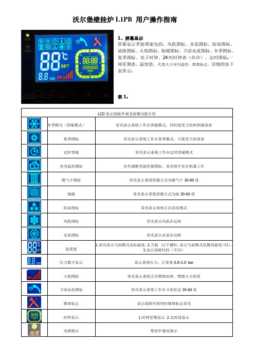
沃尔堡壁挂炉L1PB 用户操作指南1、屏幕显示屏幕显示界面图案包括:风机图标、水泵图标、防冻图标、故障图标、火焰图标、取暖图标、卫浴水流图标、冬季图标、夏季图标、电子时钟、24时时钟表(丝印)、定时图标,一周星期表、温度值,火焰大小室内温控、维修标志、详细的如下表所示:表1:LCD显示面板外观及按键功能介绍冬季模式(供暖模式)常亮表示系统工作在供暖模式,同时接受卫浴和供暖请求夏季图标常亮表示系统工作在夏季模式,只接受卫浴请求定时供暖常亮表示系统工作在定时供暖模式室内温控图标室外通断型温控器图标。
常亮则不允许机器工作暖气片图标常亮表示系统供暖方式为暖气片30-80度地暖常亮表示系统供暖方式为地30-60度防冻图标常亮表示系统正在防冻模式风机图标常亮表示风机在运转水泵图标常亮表示水泵在动转温度值1.常亮显示当前模式实际温度。
2.当按上/下键时,显示当前模式设置的温度(闪)。
3.显示故障代码(不闪)压力数字显示显示系统压力,正常值0.8-2.0 bar火焰图标常亮表示系统正在燃烧加热,燃烧大小程度卫浴水流图标常亮表示系统工作在卫浴状态30-60度维修标志显示故障代码同时维修标志常亮时钟显示 1.时钟星期显示2.定时段显示电源指示壁挂炉通电指示故障指示出现故障后,故障闪红灯,显示故障代码和维修标志开机或关机键1.通电后按动该键开机或关机,2.设置状态下,按动该键确认保存,3.在故障锁机状态按此键可以解除故障锁机状态模式选择键开机状态按动此键,进行各种供暖模式选择时间设置键在时间设置状态,按动此键进行下一步选择数据增加键1.供暖运行状态用来调节供暖温度,2.卫浴运行状态用来调节热水温度,3.时间设置调节相应数据数据降低键在开机使用壁挂炉之前,请确认以下打条件是否符合要求。
1.气阀打开,且有稳定的气压,正常气压每户可以同时开两台24KW的壁挂炉工作!2.看屏幕上显示系统压力在0.8-2bar之间,如果压力低于0.8bar请补水,打开补水阀,在壁挂炉底部有一个黑色的方形旋钮,切记补到1.5bar时马上关上补水阀,如果超压,关闭冷水阀门(从右边往左数第二根)打开补水阀,再打开热水龙头,泄到2.0bar以内,然后马上关上被水阀,如果不关会一直补水,系统压力过大超过或接近3bar时安全阀会泄压,这样浪费水还把水喷的到洗菜盒上,正常3个月以上才补一次水,有时补次水可以用一年多。
60p舷外机机使用方法
60p舷外机机使用方法
以下是 8 条关于 60p 舷外机使用方法:
1. 嘿,你知道怎么给 60p 舷外机加油不?就像给汽车加油一样,可别加错了地方哦!比如,你总不能给轮胎加油吧,那对舷外机也是同理呀!
2. 60p 舷外机启动前要检查好多地方呢!这就好比你出门前要照照镜子整理下自己,看看有没有啥不妥的地方,像线路呀、螺旋桨啥的,可都得仔细瞅瞅。
3. 哇塞,操控 60p 舷外机的时候,那感觉就像驾驭一匹烈马!你得掌握好力度和方向,不然它可不听你的哟,就像马要是不听使唤那还不乱套啦!
4. 嘿,60p 舷外机的保养可重要了呀!你对它好,它才会对你好呀!就像你对好朋友用心,朋友也会对你真诚一样。
每次用完记得清理干净呀!
5. 60p 舷外机在高速行驶的时候,真的像箭一样飞出去!这时候你可得集中注意力呀,难道你跑步的时候还能分心去想别的事吗?肯定不行呀!
6. 哎呀呀,使用 60p 舷外机可别太莽撞啦!就像走钢丝一样,得小心翼翼的,要是一个不小心,那后果可不堪设想啊!
7. 60p 舷外机的速度调节也是有讲究的哦!这可不是随便拧拧就行的,就好像调音量,大了小了都不合适呀,得恰到好处才行呢!
8. 当你熟练掌握了 60p 舷外机的使用方法,那感觉真的太棒啦!就好像你学会了一门绝世武功,在水上自由驰骋,爽歪歪呀!
我的观点结论是:60p 舷外机使用起来既有趣又有挑战性,只要按照正确的方法去操作和保养,就能让它发挥出最佳性能,带给我们愉快的体验。
意大利ALBERTI starjet冷热水高压清洗机使用说明

意大利ALBERTI starjet冷热水高压清洗机使用说明1、开机前的准备开机前检查清洗机各部位螺钉、螺母是否有松动现象,泵偏心轴箱内已加入30或40机油,需检查油位(正好漫过油镜为益)。
2、进水管连接将进水胶管套在泵体的进水口接头上,然后套上喉卡,拧紧喉卡上的螺钉,保证连接牢固且不漏气。
然后按水源的情况将另一端套在自来水龙头上或放入供水池中(进水口必须完全浸入水中),进水管要求安装过滤器,以免吸入的杂质损坏高压泵。
3、出水管连接把高压胶管的插入接头端与机具出水口上的快换接头相连;另一端与喷枪扳机式阀上的螺纹接头相连。
接法参见结构图(快换接头的接法:只要把滚花套筒向后推,再把接头往里推平即可)。
注意:高压水管不能绞结,尽量延展、拉直。
4、电源连接首先要确定电源电压与标牌规定相一致,清洗机所采用的固定电源的连接应由专业人员进行,并应符合GB/T16895的要求。
如果使用延伸电源线,插头和插座应是防水结构的。
连接插座时,必须将清洗机的开关定在“关”的位置。
5、可更换式喷头本机喷枪可通过更换喷头调节喷出水流,短枪头为圆孔束状水流,长枪杆为扇形水流。
圆孔束状水流——该喷头能产生束状强力射流,用于污垢特别严重的表面。
如农业机械、建筑机械等。
扇形水流——该喷头产生扇形射流,散射角大,对被清洗物体的冲击力小,能用于大面积污垢表面的清洗,如轿车、公共汽车、卡车、拖接机和其它各种车辆、船舶;菜场及食品加工场,宾馆厨房;浴池、游泳池;畜舍及畜牧栅栏,高层建筑的外墙清洗等。
6、启动机器检查进水管与出水高压管已经连接可靠,电源插座接好,就可以接通电源,扣动喷枪的扳机,待机具内的空气排净后,即可有高压水喷出。
首次使用时,空气排放较慢,可先将出水高压管取下,待出水接头处有水喷出已无气体时关机,由快速接头处接上高压管,再重新开机使用。
7、若用水箱向泵供水时,应在开机的同时,从进水管向泵内灌水,半扣动喷枪的扳机,以使管路中的空气排出,待泵正常工作后,将进水管置于水箱中即可。
数显德国博尔豪夫拉力记说明书
数显德国博尔豪夫拉力记说明书
数显沥青延伸仪适用于测定道路石油沥青、供应商河北大宏实验仪器有限公司,液体沥青蒸馏残留物和乳化沥青蒸发残留物等材料的延度试验,符合JTGE20-20xx《公路工程沥青及沥青混合料试验规程》规范要求。
数显沥青延伸仪内胆采用进口不锈钢板折弯而成,温度自控数显采用先进的永磁低速同步电机。
采用了大规模集成电路,对延伸长度进行控制,可分别记忆三个试件及其平均值,计数真实准确;对温度控制采用了先进控制技术,控温精度高,热冲现象很小。
带有水循环装置,水温均匀度好。
整机结构合理、自动化程度高,是较理想的实验室试验设备。
1、将仪器安放在稳固水平的基础上。
2、在水槽中加入清洁的水后(无水情况下严禁开机),检查各电器按钮工作是否正常。
3、检查丝杆传动是否灵活。
一般分别检查两端和中部的转动情况即可知道。
欧图II反馈抑制器用户手册

User's ManualVersion 1.2 April 18, 2008EnglishDIGITAL PROCESSORAutomatic Feedback KillerTERMINATOR IIc All rights reserved to ALTO. All features and content might be changed without prior notice. Any photocopy, translation, or reproduction of part of thismanual without written permission is forbidden. Copyright 2007 Seikaku GroupSEIKAKU TECHNICAL GROUP LIMITEDNO. 1, Lane 17, Sec. 2, Han Shi West Road, Taichung 40151, Taiwan T el: 886-4-22313737email: alto@ Fax: 886-4-22346757NF02949-1.2IMPORT ANT SAFETY INSTRUCTIONWARNINGTo reduce the risk of electric shockand fire, do not expose this equipmentto moisture or rain.1.2.3.4.5.6.7.8.9.10.Dispose of this product shouldnot be placed in municipal wasteand should be separate collection.11.12.Move this Equipment only with a cart,specified by themanufacturer, orsold with theEquipment. Whena cart is used, usecaution whenmoving the cart /equipmentcombination toavoid possiblePermanent hearing loss may be caused byexposure to \ extremely high noise levels.The US. Government's Occupational Safetyand Health Administration (OSHA) hasspecified the permissible exposure to noiselevel.These are shown in the following chart:According to OSHA, an exposure to high SPL inexcess of these limits may result in the loss ofheat. To avoid the potential damage of heat, it isrecommended that Personnel exposed toequipment capable of generating high SPL usehearing protection while such equipment isunder operation.may be sufficient to constitute the risk of electricProtective Ground T erminalAC mains (Alternating Current)Hazardous Live T erminalON: Denotes the product is turned on.OFF: Denotes the product is turned off.The apparatus shall be connected to a mainssocket outlet with a protective earthingconnection.The mains plug or an appliance coupler is usedas the disconnect device, the disconnect deviceshall remain readily operable.CAUTIONDescribes precautions that should be observed toprevent damage to the product.Keep this Manual in a safe place.Be aware of all warnings reportedwith this symbol.moisture.Clean it only with dry cloth. Do not usesolvent or other chemicals.Do not damp or cover any cooling opening.Install the equipment only in accordance withthe Manufacturer's instructions.Power Cords are designed for your safety. Donot remove Ground connections! If the plugdoes not fit your AC outlet, seek advice froma qualified electrician. Protect the powercord and plug from any physical stress toavoid risk of electric shock. Do not placeheavy objects on the power cord. This couldcause electric shock or fire.Unplug this equipment when unused for longperiods of time or during a storm.Refer all service to qualified service personnelonly. Do not perform any servicing other thanthose instructions contained within theUser's Manual.To preven t fire and damage to the product,use only the recommended fuse type asindicated in this manual. Do not short-circuitthe fuse holder. Before replacing the fuse,make sure that the product is OFF andHOURS X DAY EXAMPLE864321,510,50,25 or lessSPL90929597100102105110115Small gigtrainSubway trainHigh level desktop monitorsClassic music concertRock concert1. TERMINATOR II QUICK START - SET UP MODE1.1 After connecting TERMINATOR II to the mixer channels or subgroups follow these points:1.2 Press and hold the BYPASS button (for more than 4 seconds) related to the channel you want to set up (CHANNEL 1 or CHANNEL 2): all 24 filter leds will start flashing1.3 Start generating intentional feedbacks increasing slowly the GAIN/VOLUME on the mixer: TERMINATOR II will activate gradually the filters and the correspondent leds will light1.4 Usually 10 to 16 filters are enough to guarantee a safe set up without modifying the audio timbre1.5 Remember you can use up to 2 independent channels connected to TERMINATOR II1.6 T o exit SET UP MODE and to STORE the fixed filter press quickly the related channel BYPASS button: all filter leds turn on for a few seconds, then only the stored ones keep on lighting1.7 Now TERMINATOR II is set on LIVE MODE And in such cases, all the expenses will be charged to the buyer .3.5 In no event shall be liable for any incidental or consequential damages. L TO Some states do not allow the exclusion or limitation of incidental orconsequential damages, so the above exclusion or limitation may not apply to you.3.6 This warranty gives you the specific rights, and these rights are compatible with the state laws, you may also have other statutory rights that may vary from state to state.7. WARRANTYQUICK START2.1 During the performance the accidental LIVE feedbacks are automatically detected and killed: a new led will light to indicate the activation of a new LIVE filter2.2 If occasionally all 24 filters are activated (all filter leds on) and new LIVEfeedback occurs, TERMINATOR II is able to kill the new feedback substituting the oldest less-used filter: the correspondent led will start flashing2.3 Y ou can operate in real time on the LIVE MODE VARIA TIONS to adjust the filter Q according to your audio source: generally for Music we suggest to turn the knob towards 1/80th, for Speech towards 1/5th)2.4 If you need to RESET the LIVE filters (keeping the FIXED ones previously stored during the SET UP MODE) press and hold the BYPASS button for about 2 seconds till only the FIXED filter leds keep on lighting2.5 If you need to RESET completely TERMINATOR II and start a new SET UP , press and hold the BYPASS button for more than 4 seconds till all 24 filter leds will start flashing2. TERMINATOR II QUICK START - LIVE MODEAbnormal service or repairing by anyone other than the qualified personnel or technician.and contact telephone number.2.3 A brief description of the defect will be appreciated.2.4 Please prepay all the costs involved in the return shipping, handling and insurance.3. TERMS AND CONDITIONS3.1 warrants that this product will be free from any defects in materials L TO and/or workmanship for a period of 1 year from the purchase date if you have completed the Warranty Registration Card in time.3.2 The warranty service is only available to the original consumer, who purchased this product directly from the retail dealer, and it can not be transferred. 3.3 During the warranty service, may repair or replace this product at its L TO own option at no charge to you for parts or for labor in accordance with the right side of this limited warranty.3.4 This warranty does not apply to the damages to this product that occurred as the following conditions:Instead of operating in accordance with the user's manual thoroughly, any abuse or misuse of this product. Normal tear and wear.The product has been altered or modified in any way.Damage which may have been caused either directly or indirectly by another product / force / etc.the returned machine, and give detail information about your return address 2.2 Please provide a copy of your sales receipt or other proof of purchase with unit from any other extra damage.product is well packed in its original shipping carton, and it can protect your 2.1 In case of return for any warranty service, please make sure that the2. RETURN NOTICEyour warranty service. 1. WARRANTY REGISTRATION CARDT o obtain Warranty Service, the buyer should first fill out and return the enclosed Warranty Registration Card within 10 days of the Purchase Date.All the information presented in this Warranty Registration Card gives the manufacturer a better understanding of the sales status, so as to provide a more effective and efficient after-sales warranty service. Please fill out all the information carefully and genuinely, miswriting or absence of this card will voidIN THIS MANUAL:1. INTRODUCTION........................................................................12. FEATURES...............................................................................13. CONTROL ELEMENTS..............................................................24. USER SETUP ...........................................................................45. INSTALLA TION & CONNECTION.................................................76. TECHNICAL SPECIFICATIONS..................................................10 7. WARRANTY (11)2. FEATURESThank you for your purchasing of the L TO TERMINATOR II. The TERMINA TOR II is a Dual Channel Digital Processor . It is designed to provide state of the art Feedback elimination processing, for fixed installation or live event, while maintaining a simple and intuitive control interface.The TERMINATOR II provides up to 24 filters per channel (CH1 & CH2), offers independent selectable modes, live filters lift, process bypasses, continuously variable types of filtration, with widths between and Octave of which are all available on a intuitive user interface front panel.th th 1/801/5 Enjoy your TERMINATOR II and make sure to read this Manual carefully before operation!24 Programmable Filters per Channel Dual Independent Channel Processing Live and Fixed Filter Modes Automatic Live Filter Release Selectable Application of proprietary Filter Variations (Music/Speech)L TO 2Input Channel Metering 24 LED Filter Metering per Channel2 XLR and 2 x TRS Electronically Balanced Inputs and Outputs Selectable Operating Level Switches (+4 dBu / -10 dBv) Rear Panel Lockout Switch1. INTRODUCTION2 x female XLR and 2 x 1/4" TRS Electronically Balanced / Unbalanced, RF filter suppressor Max Input line level 2 x male XLR and 2 x 1/4" TRS Electronically Balanced / Unbalanced, RF filter suppressor Max Output level Dynamic Range D/A Performance D/A ConversionSample Rate THD+N % Power Consumption Power Requirement 6. TECHNICAL SPECIFICA TIONAnalog InputsInput impedance 30k ohm Balanced / 15k ohm Unbalanced +20.5 dBuAnalog OutputsOutput impedance 100 Ohm Balanced / 50 Ohm Unbalanced +14.5 dBuA/D Performance 114 dB, A-weighted A/D Conversion 24 bitDynamic Range 100 dB, A-weighted 24 bitSystem Performance 48 kHzDynamic Range 100 dB, A-weighted 0.01 %, 1 kHzFrequency Response20 Hz to 20 kHz, +/- 0.5 dB Inter channel Crosstalk Crosstalk input to output Operating Voltage230 VAC 50/60 Hz 115 V AC 50/60 Hz 15 W100 dB, A-weighted 100 dB, A-weightedPhysicalS/N Ratio100 dB, A-weightedDimension Net Weight483 x 195 x 44 mm 3.1kgFront Panel:The TERMINATOR II offers 24 notch filters (RED LED) for each channel, which are used to indicate the number of active notch filter . The LEDs that always blink for each channel is the last Live inserted notch filter .a -This button is used to bypass the notch filters in the s ignal path by pressing quickly (about 1 second).) is used to reset the LIVE filters (CLEAR 2 Sec.).c -BYPASS button (more than 4 Sec.) is used to reset the fixed filters and enter the SETUP Mode (SETUP 4 Sec.).For more information of filter reset, please see the Clearing Filters in the USER SETUP section.b -Pressing and holding the BYP ASS button (about 2 Sec Pressing and holding the3. CONTROL ELEMENTS 3. CONTROL ELEMENTS2 BypassThis knob is used in LIVE MODE to select the application of AL TO proprietary notch filter , independently on CH1 & CH2.Each selected mode controls the width ( to of the notch filter used to remove the feedback, the velocity of the filter activation and the sensibility in the feedback analysis.th th1/801/5) 3 LIVE Mode VariationsThese four LEDs indicate input level of the TERMINATOR II with a range from -10 dBu to +18 dBu.NOTE: For maximum performance and proper operation, the average input signal should consistently light up at the 0 dBu LED and the +10 dBu LED lighting occasionally.4 Input Level Bar GraphThis LED indicates that there is signal clipping at the Inputs. If necessary, verify the correct position of input selector -10dBv /+4dBu, or setting the level of the chain with a external pink noise signal. 5 Clip LED6 Power SwitchIt switches your TERMINATOR II On/Off .ON LINE with the Outputs of the Mixer1- Connect the Outputs L -R from the mixer to the inputs CH 1 & CH 2 ofTERMINATOR II with the XLR or TRS (tip-ring-sleeve) stereo jack.2- Connect the Outputs CH1 & CH2 of TERMINATOR II at the Inputs of power amplifiers.3- Set the sensitivity at +4 dBu on the TERMINATOR II and adjust the L -R fader control on the MIXER for having a necessary level on TERMINATOR II.For maximum performance and proper operation, the average input signal should consistently light up at the 0 dBu LED and the +10 dBu LED lighting occasionally.3. CONTROL ELEMENTS 5. INSTALLA TION AND CONNECTION3. CONTROL ELEMENTS 3. CONTROL ELEMENTSRear Panel:Two types of input connectors are provided for input connections: 2 x female locking XLR type connectors, and 2 x 1/4" TRS jack connectors (tip-ring-sleeve). The maximum input level that the processor can accept is +20 dBu (ref.: 0.775Vrms).This button allows you to select between either +4 dBu or -10 dBv nominal operating level.This switch locks/unlocks all access to the front panel of the TERMINATOR II.7 AC Inlet and Fuse holder9 Input/Output Connectors10 Operating Level Switch11 Lock Switch8 Voltage SelectorThis switch has two choices for voltage, 100-120 VAC or 220-240 V AC.Standard IEC receptacle. Connect your TERMINATOR II to the AC Inlet with the supplied AC power cord. Before powering up your TERMI N ATOR II for the first time, make certain the stated power requirement of the unit matches the voltage supplied by the AC socket.If the fuse blows, replaced with a fuse of the correct type only.Insert on the SUB GROUP/MAIN L-R of the Mixer1- Connect the TRS (tip-ring-sleeve) stereo jack into the Mixer SUB GROUP/ MAIN L-R, Insert sock et.2- Connect the Send stereo jack (unbalanced) to the CH1 Input of TERMINATOR II and the CH1 Output of TERMINATOR II with a Retu rn ste reo jack (unbalanced). 3- Set the sensitivity at -10 dBu on the TERMINATOR II and adjust the SUB GROUP/ MAIN L-R, fader control on the MIXER for having a necessary level on TERMINATOR II.For maximum performance and proper operation, the average input signal should consistently light up at the 0 dBu LED and the +10 dBu LED lighting occasionally.3. CONTROL ELEMENTS5. INSTALLA TION AND CONNECTION4. USER SETUPThere are three basic ways you can use the TERMINATOR II combine with your audio system. It can be:1. Connected to a MIC channel of a MIXER, into the "Insert" jack (send/return).2. Connected to the SUBGROUP/MAIN OUTPUTS (L/R) of a MIXER into the "Insert" jack (send/return).3. Connected "ON LINE" between mixer and PA system. From output of the Mixer to i n put of TERM INA TOR II and from Output of TERMINATOR II to P A input (Stereo Amplifier).The connection of TERMINATOR II to Insert points, is probably the bestselection, the levels present in most mixers are pre-fader , (normally 10 dBu) and flow direct to TERMINA TOR II. In this way any fader level variations do not modified the setup of TERMINATOR II.For the best performance and proper operation, the average input signal should consistently light up at the 0 dBu LED and the +10 dBu LED lighting occasionally.The above setup is used when insert points are not available, set the TERMINATOR II at +4 dBu, this value is correct when you connect the outputs of any mixer directly to the input of TERMINATOR II.For the best performance and proper operation, the average input signal should constantly light around 0 dBu LED and the +10 dBu LED should light only occasionally. 2 SETUP & LIVE ModeThe TERMINATOR II offers a total number of 24 notch filters for each channel (CH 1/CH 2) and two main operation modes:a -SETUP mode, with the fixed filters.b -LIVE mode, with the free filters not used in SETUP mode.The SETUP mode is used to detect and remove feedback problems in the audio system due to the microphone placement, different environments shapes, etc. Once these filters are set, they can't be removed unless you reset then again.The LIVE mode is used to detect and remove feedback in "real-time", during the musical events.1. Using SETUP Mode (SOUND CHECK)Fixed filters are set before a performance in a process called ringing out a system, this is done after all other setting system has been done.a -First, bring down the main mix, turn off all music sources and open the MIC (if you use Vocalist) or the different MIC (if you use a Sub-Group).The filters, not used in SETUP mode, automatically work in LIVE mode, the last filter included blink.free 1 Setting Audio System3. CONTROL ELEMENTS 5. INSTALLATION AND CONNECTIONInsert on the MIC channel1- Connect the TRS (tip-ring-sleeve) stereo jack into the mixer MIC channel, Insert socket.2- Connect the Send stereo jack (unb alan ced) to the CH1 Input of TERMINATOR II and the CH1 Output of TERMINATOR II wit h a Return stereo jack (un bala nced ).3- Set the sensitivity at -10 dBu on the TERMINA TOR II and adjust the MIC Gain control on the MIXER for having a necessary level on TERMINATOR II. 4- Repeat the same step connections for the CH2 of TERMINATOR II if you like to use.For maximum performance and proper operation, the average input signal should consistently light up at the 0 dBu LED and the +10 dBu LED lighting occasionally.Hz+3+2+1 0-1-2-3-4-5-6-7-8-9d B u d B ud -Set the level of each CHANNEL with PFL and slowly turn u p the Main Mix er Volume, raising the gain of the system, until feedback occurs.e -The TERMINATOR II will detect and remove feedback by placing notch filters on the proper frequencies. Continue to slowly raise the gain until allfeedbacks have been eliminated, then exit from SETUP Mode by pressing and releasing the BYPASS button quickly.All LED turn ON for few seconds, indicating fixed filters are STORED and automatically LIVE Mode is selected, the remaining filters are available in LIVE MODE.If all 24 filters have been used in SETUP Mode, the SETUP Mode is left automatically and no more filters are available in LIVE Mode.2. Using LIVE Mode (REAL TIME)The TERMINATOR II operates normally in LIVE Mode (24 notch filters minus the fixed used filters ). Live Mode filters are set on the feedback frequency as soon as a new feedback is detected, according to the knob position of the selected LIVE Mode Variations (from MUSIC to SPEECH).If all LIVE filters are used and a new feedback occurs, the oldest LIVE filter is cleared and reallocate to the new feedback frequency (the correspondent led will light).The TERMINATOR II will continue to search feedback frequency through the LIVE notch filters.4. USER SETUPc -All the 24 LEDs and the BYPASS LED will start flashing, indicating SETUP mode is selected for CH1 or CH2 or together .MUSIC High Q mode, (use notch filters at Octave), continuously variable until SPEECH Low Q mode, (use notch filters at Octave).th 1/80th 1/5ALTO Notch Filter Q Diagramb -Place the TERMINATOR II in SETUP Mode by pressing and holding the BYP ASS button for more than 4 seconds.3 CLEARING FILTERST o reset the LIVE filters, press and hold the BYPASS button on the selectedchannel (for about 2sec till the live filter leds will switch off). The currently active filters will be cleared and the assigned LED will turn off.If you wish to "reset" all the filters, continue to hold the BYP ASS button (more than 4 seconds) until all filter LEDs are "blinking", indicating that you have entered the SETUP Mode and that all filters FIXED and LIVE have been cleared. 4 LOCK ON/OFFWhen you finished setting the TERMINATOR II, you can save your setup, switch ON the LOCK selectors in the rear panel.After this it will be impossible to operate on front panel. 4. USER SETUP5 AUTOMATIC FILTER RELEASEThe AL TO TERMINATOR II provides the user with 24 notch filters, for each channel, they are enough for normal performances. If severalnumbers of filters are required, (more than 16), we strongly recommend to operate a new setup of the sound system.Anyway, even if the TERMINA TOR II uses very narrow notch filters, accordingly with the selected application type, unused notch filters must be avoided, to always guarantee the best audio performance.The TERMINATOR II constantly monitors the status of the LIVE filters and automatically removes the ones that are no longer necessary.。
图尔波
TURBO图尔波康派特机电提供:除尘器所使用的电磁脉冲隔膜阀(电磁脉冲阀)内部设有两条气路,由电磁先导阀控制其开通和关闭。
由于先进的设计,使阀门具有良好的流通特性,压力损失极低。
其精良的制造工艺,又保证了电磁阀在得到脉冲电信号时极为快速地开启(0.023-0.027秒)和在完成设定的脉冲宽度后迅速关闭,使得喷吹性能更为强大。
阀体和阀盖用铝合金压铸而成,用不锈钢螺栓相互连接。
通径在11/2”以下的阀门为单膜片阀,11/2”以上的阀门(含11/2”)为双膜片阀。
先导阀膜片和脉冲阀主膜片采用的是内部带有特殊夹织物的加强橡胶制成,使得膜片具有极高的拉伸强度、抗老化性和极低的磨耗量,从而喷吹100万次不损坏。
电磁线圈按F级的绝缘等级铸在一个防护等级为IP65的插头内,绝不会受到外界条件的干扰,因而500万次通电吸合不损坏。
电磁线圈可以在脉冲阀芯上360°旋转并可在任一位置安装,极大方便了使用者的不同需求。
外线接线盒也可4×90°旋转,既方便了接线又能防止在露天安装时雨水的进入。
先导阀亦可安装在距脉冲阀体较远的控制盒内对脉冲阀进行远程气动控制。
TURBO图尔波脉冲阀还可选装消声器使之安静工作,在环保除尘的同时又避免了躁声污染周边环境。
TURBO图尔波电磁脉冲阀工作原理膜片将先导阀和脉冲阀体分成三个气室。
分气包输出的压缩空气经脉冲阀阀座的进气口进入下气室,又经主膜片的通气孔到达脉冲阀体内的中气室后,又迅速通过先导阀膜片上的通气孔到达先导阀内的上气室,并同时也有少量压缩空气通过脉冲阀体上的泄气孔排往大气(但此过程极短,以几毫秒计,可略)。
但由于上气室作用在先导阀膜片上的压力大于中气室(作用面积大于中气室的作用面积),使先导阀膜片弹性变形封住中气室出口,故而关闭通往上气室的气路。
同时中气室作用在脉冲阀主膜片上的压力也大于阀座内的压力(同样是作用面积大),使主膜片变形,几乎同时封住下气室的喷吹口。
德国威能turboTEC_pro_及_turboTEC_plus_用户使用说明书
3
操作说明 .......................................................................6 推荐配件
3.1 3.2
关于保修期的说明........................................................... 6 特定用途 ........................................................................... 6
因此,不要擅自更改如下所列项目: - 壁挂炉; - 壁挂炉的运行环境; - 燃气、水供应管路和供电线路; - 进气/排烟系统; - 在壁挂炉周围进行的、会影响壁挂炉运行安全性的任何
结构性改变。
安全说明 请遵守如下安全说明和规范。
危险! 易燃气体和空气的混合物可能引起爆炸! 不要在壁挂炉附近使用或存放易燃易爆物质,如 汽油或油漆。
3.6
节能提示 ........................................................................... 7
4 4.1 4.1.1 4.1.2 4.2 4.2.1 4.2.2 4.3 4.4 4.4.1 4.4.2
4.4.3 4.5 4.5.1 4.5.2 4.5.3 4.5.4 4.6
1.4
手册的适用性................................................................... 3
2
安全性 ...........................................................................4
- 1、下载文档前请自行甄别文档内容的完整性,平台不提供额外的编辑、内容补充、找答案等附加服务。
- 2、"仅部分预览"的文档,不可在线预览部分如存在完整性等问题,可反馈申请退款(可完整预览的文档不适用该条件!)。
- 3、如文档侵犯您的权益,请联系客服反馈,我们会尽快为您处理(人工客服工作时间:9:00-18:30)。
电磁线圈无电
电源无输出、导线断、虚接
电磁线圈烧毁(电压过高或不稳)
更换新线圈、增设稳压装置
电压过低(低于额定电压10%)
检查导线电阻,必要时更新
电磁铁不吸合或吸合不到位
芯柱弯曲,电磁铁卡死或卡滞
更换配件
电压过低(低于额定电压10%)
使电压达到额定值
气包无压或压低
进口阀门未开、管线或阀门漏气
10.除尘器在没有防雨设施的情况下,不要将电磁线圈接线插座上的入线口朝上安装,以防雨水进入。接线插座内的接线板与其外壳可以进行4×90°旋转;
11.电磁线圈与接线插座间有橡胶密封垫,可保证插销与插座间的进水造成短路。接线后用螺钉将两者旋紧;
12.不要自行拆、装先导阀。
四、故障及排除
故障显示
故障原因
调整及排除方法
地址:南京建邺区庐山路158号
更换密封圈
膜片方向装反
调整安装方向
脉冲阀漏气
螺钉未紧,安装面漏气
坚固螺钉
销声器孔漏气是阀内压力未平衡
手或机械方法强制平衡若干次
膜片方向装反,使小膜片反向变形
更换小膜片
气源不洁造成膜片渗气孔堵塞
疏通膜片渗气孔
与膜片接触的表面不洁或有异物
擦试清除
大、小膜片机械损坏
更换相应配件
大膜片磨损
更换大膜片
供气量小、阀内压力平衡时间长
13.膜片数量:
FP60型2.5”脉冲阀为双膜片阀;
14.可选装消声器使除尘器安静工作,连接螺纹为G3/8”。
三、现场安装及注意事项:
1.必须在系统完全卸压的情况下拆、装脉冲阀;
2.安装前,应清净气包及管线内的锈蚀和各种污物;
3.脉冲阀必须现场进行最终安装。
4.与插接式脉冲阀相连接的喷吹管外壁应光滑,外径尺寸应符合要求,管端必须倒圆角或4×15°角并去除毛刺,以防损坏径向密封圈。安装时须在喷吹管的外壁涂微量润ห้องสมุดไป่ตู้油(脂)以使安装顺畅;
5.装配主膜片前,应先将复位弹簧定位于脉冲阀阀体内,不得漏装;
6.主膜片上的通气孔必须对准脉冲阀阀体和脉冲阀法兰相应的通气凹槽,否则会使气路闭锁;
7.为使之寿命长久,主膜片的安装面和喷吹口必须干净、光洁,不得有任何毛刺存在;
8.端面密封用O型密封必须置于脉冲阀法兰相应的沟槽内,确保密封可靠;
9.在运输过程和现场安装脉冲阀时,不得磕碰电磁线圈部位,以免阀芯受外力变形而使阀门失效;
提供大流量压缩空气
不能正常喷吹
喷吹管出口阀门未打开
开启出口阀门
气源不洁造成膜片渗气孔堵塞
疏通膜片渗气孔
五、易损备件
1.脉冲阀主膜片,型号为M50;
2.先导阀膜片,型号为M25
3.电磁线圈,型号为BHP,24V/DC(220V/AC,110V/AC,24V/AC)
意大利TURBO图尔波公司中国代理
南京康派特机电设备有限公司
二、技术性能:
1.工作压力范围:0.5bar~7.5bar;
2.工作介质:干燥、无油、洁净的压缩气体;
3.使用环境:
-40℃~+80℃(常规膜片),
-30℃~+200℃(高温膜片);
4.工作电压:
交流(AC)24-110-230V/50-60HZ 19VA
直流(DC)24V 15W
5.电磁线圈绝缘等级:F级;
意大利TURBO公司FP60型
电磁脉冲隔膜阀使用说明书
南京康派特机电设备有限公司
意大利TURBO公司FP60型电磁脉冲阀使用说明书
意大利TURBO公司设计制造的FP60型电磁脉冲阀,以其设计的先进性和精良的制造工艺使阀门具有良好的流通特性,压力损失极低,喷吹性能更为强大。
一、FP60型2.5”直角式脉冲阀外形尺寸、安装示意、安装条件见附图。
6.电磁线圈低能耗:符合国际电工IEC335标准;
7.电磁线圈允许电压波动:±10%;
8.电磁线圈安装角度:360°;
9.接线盒保护等级:IP65,接线盒螺纹:PG9;
10.控制形式:直控式和气控式两种;
11.阀门开启速度:0.023-0.027秒;
12.使用寿命:膜片100万次喷吹,电磁线圈500万次吸合;
开启进口阀门、管线堵漏
气包升压慢
空压机能力小
更换大规格或两台同时供气或增设贮气罐
进气管径小、管线长、气包多
加大入口管径、管线合理分路
气包不能保压
安装前未试压,气包漏气
检查并补焊气包漏气点
脉冲阀漏气
检查漏气部位,针对性解决
脉冲阀与喷吹管螺纹接口漏气
漏气点堵漏
插接式阀喷吹管径小
更换大截面密封圈
插接式阀内橡胶密封圈损坏
