B101AW01 V2 Functional Spec (HW 0A)_1106_2008_6-21v-left
Moxa MiiNePort W1系列无线LAN嵌入式串行设备服务器产品介绍说明书

MiiNePort W1SeriesWireless LAN embedded serial device serversFeatures and Benefits•IEEE802.11b/g compatible•AES,WEP64/128-bit,WPA,WPA2,PSK,802.11i security support•Low power consumption(1.18W)•1serial port,up to921.6kbps•1Ethernet port,10/100Mbps•HTTPS/SSH support for configuration•Fast roaming to enhance connection reliabilityCertificationsIntroductionThe MiiNePort W1Series provides serial to IEEE802.11b/g embedded wireless solution that includes compact sizes and ultra-low power consumption as features.Numerous operation modes are designed to fulfill the requirements of embedded module plete driver support reduces software redesign effort and accelerate time to market.SpecificationsEmbedded SystemCPU32-bit Arm CoreMemoryFlash16MBSDRAM64MBInput/Output InterfaceConfigurable DIO Channels(by software)8Ethernet InterfaceStandards IEEE802.3for10BaseTIEEE802.3u for100BaseT(X)IEEE802.3x for flow control10/100BaseT(X)Port Auto MDI/MDI-X connectionEthernet Software FeaturesConfiguration Options Web Console(HTTP/HTTPS),Windows Utility,Telnet Console,Serial Console Management ARP,Device Search Utility(DSU),DHCP Client,DNS,HTTP,IPv4,SMTP,SNMPv1/v2c/v3,TCP/IP,Telnet,UDP,Web Console,ICMPWindows Real COM Drivers Windows95/98/ME/NT/2000,Windows XP/2003/Vista/2008/7/8/8.1/10(x86/x64),Windows2008R2/2012/2012R2(x64),Windows Embedded CE5.0/6.0,Windows XPEmbeddedLinux Real TTY Drivers Kernel versions:2.4.x,2.6.x,3.x,4.x,and5.xFixed TTY Drivers SCO UNIX,SCO OpenServer,UnixWare7,QNX4.25,QNX6,Solaris10,FreeBSD,AIX5.x,HP-UX11i,Mac OS XAndroid API Android3.1.x and laterMIB Device Settings MIB,RFC1213,RFC1317Time Management SNTPSerial InterfaceNo.of Ports1Serial Standards TTLOperation Modes Real COM mode,TCP Server mode,TCP Client mode,UDP mode,RFC2217mode,DisabledBaudrate50bps to921.6kbps(supports non-standard baudrates)Data Bits7,8Stop Bits1,2Parity None,Even,OddFlow Control None,RTS/CTS,XON/XOFFSerial SignalsRS-232TxD,RxD,RTS,CTS,DTR,DSR,DCD,GNDWLAN InterfaceAntenna External,2dBiSpread Spectrum DSSS,OFDMTransmission Rate802.11b:11Mbps802.11g:54MbpsTyp.-71dBm@54MbpsReceiver Sensitivity for802.11g(measured at2.437GHz)Transmitter Power for802.11b16±1.5dBm@11MbpsTransmitter Power for802.11g14±1.5dBm@54MbpsWLAN Modes Ad-hoc Mode,Infrastructure modeWLAN ModuleModule Antenna Connectors1I-PEX connectorsAntenna CharacteristicsAntenna Type Omni-directionalPower ParametersInput Current400mA@3.3VDCInput Voltage 3.3to5VDCReliabilityAutomatic Reboot Trigger Built-in WDTPhysical CharacteristicsForm Factor Type Drop-in modulesDimensions44.4x44.4x9.7mm(1.75x1.75x0.38in)Weight15.35g(0.03lb)Environmental LimitsOperating Temperature MiiNePort W1/W1-ST:0to55°C(32to131°F)MiiNePort W1-T:-40to75°C(-40to167°F)Storage Temperature(package included)-40to60°C(-40to140°F)Ambient Relative Humidity5to95%(non-condensing)Standards and CertificationsEMC EN55032/24EMI CISPR32,FCC Part15B Class AEMS IEC61000-4-2ESD:Contact:4kV;Air:8kVIEC61000-4-3RS:80MHz to1GHz:3V/mIEC61000-4-4EFT:Power:1kV;Signal:0.5kVIEC61000-4-5Surge:Power:1kVIEC61000-4-6CS:150kHz to8MHz:3V/m;Signal:3V/mIEC61000-4-8PFMFIEC61000-4-11Environmental Testing IEC60068-2-1IEC60068-2-2IEC60068-2-3Radio Frequency EN300328,EN301489Safety EN60950-1,UL60950-1Shock IEC60068-2-27Vibration IEC60068-2-6DeclarationGreen Product RoHS,CRoHS,WEEEMTBFTime441,378hrsStandards Telcordia SR332WarrantyWarranty Period5yearsDetails See /warrantyPackage ContentsDevice1x MiiNePort W1Series device server1x evaluation board(MiiNePort W1-ST)Cable1x Ethernet crossover cable(MiiNePort W1-ST)1x null modem serial cable(MiiNePort W1-ST)Antenna1x2.4/5GHz(MiiNePort W1-ST)Power Supply1x power adapter,universal(MiiNePort W1-ST)1x power cord,EU type(MiiNePort W1-ST)1x power cord,US type(MiiNePort W1-ST)Documentation1x document and software CD1x quick installation guide1x warranty cardDimensionsOrdering InformationModel Name No.of Serial Ports Supported Baudrates Operating Temp.With MiiNePort W1With Evaluation Board MiiNePort W1150bps to921.6kbps0to55°C✓–MiiNePort W1-T150bps to921.6kbps-40to75°C✓–MiiNePort W1-ST150bps to921.6kbps0to55°C✓✓©Moxa Inc.All rights reserved.Updated Nov08,2019.This document and any portion thereof may not be reproduced or used in any manner whatsoever without the express written permission of Moxa Inc.Product specifications subject to change without notice.Visit our website for the most up-to-date product information.。
电动执行器的对比
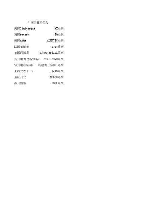
厂家名称及型号美国limitorque MX系列英国rotork IQ系列德国auma AUMATIC系列法国伯纳德 ST14系列德国西博斯 SIPOS 5Flash系列扬州电力设备修造厂 2SA8 2SQ8系列常州电站辅机厂 施耐德(SND)系列上海仪表十一厂 上仪ID系列重庆川仪 M8000系列苏州博睿 BDⅡ系列阀位检测方式转矩检测方式非接触式光电绝对编码器电子测量现场可设 霍尔技术编码器 须电池支持电子测量现场可设非接触式磁电绝对编码器磁电编码测量现场可设非接触式光电绝对编码器 光电编码测量现场可设电位器 易磨损电子测量现场可设霍尔技术编码器 须电池支持电子测量现场可设非接触式光电绝对编码器 采用其他厂家成品 配件成本高电子测量现场可设霍尔技术编码器 须电池支持压力传感器检测动态显示霍尔技术编码器 须电池支持电子测量现场可设非接触式磁电绝对编码器 自主研发电子测量现场可设电气防护防爆等级接线盒二次密封显示方式IP68ExdllCT4 ExdllBT4可选有LCD+指示灯IP68ExdllCT4 ExdllBT4可选有LCD+指示灯IP67可提供IP68ExdllCT4 ExdllBT4可选无LCD+指示灯IP68ExdllCT4/5/6 ExdllBT4/5/6可选无LCD+指示灯IP67可提供IP68无LCD+指示灯IP67可提供IP68ExdllCT4无LCD+指示灯IP67可提供IP68ExdllCT4/5/6 ExdllBT4/5/6可选有LCD+指示灯IP68有LCD+指示灯IP67可提供IP68ExdllCT4无LCD+指示灯IP68ExdllCT4有LCD+指示灯输出组态调试方式故障诊断开关量4个标准可组态双稳态触点免开盖调试有自检功能 诊断执行器的故障有4个标准可组态双稳态触点免开盖调试有自检功能 诊断执行器的故障有4个标准可组态双稳态触点免开盖调试有自检功能 诊断执行器的故障有4个标准可组态单稳态触点免开盖调试有自检功能 诊断执行器的故障有8个标准单稳态可组态触点需开盖调试有自检功能 诊断执行器的故障有8个标准单稳态可组态触点免开盖调试有自检功能 诊断执行器的故障有LCD+指示灯免开盖调试有自检功能 诊断执行器的故障有LCD+指示灯免开盖调试有自检功能 诊断执行器的故障有4个标准可组态单稳态触点免开盖调试有自检功能 诊断执行器的故障有4个双稳态2个单稳态标准可组态触点免开盖调试有自检功能 诊断执行器的故障有调节量ESD两线控制调速控制DeviceNet Modbus Profibus FF 有有有间断运行有有有有有有有间断运行有有有有有有有间断运行有有有有有有有间断运行无有有有有变频调速无有有有有有无变频调速无无有有有间断运行有有有间断运行有变频调速无有有无有有有间断运行有有有研发中死区设置电流标定丢信动作0.1~9.9%无位置可设0.1~9.9%无位置可设可设无位置可设可设无位置可设可设无位置可设0.3~9%无0.5~9%0.1~9.9%可设0.1~9.9%/自适应有位置可设。
广州致远电子ZM602系列Wi-Fi模块数据手册说明书
©2022 Guangzhou ZHIYUAN Electronics Co., Ltd.ZM602系列Wi-Fi 模块数据手册Wi-Fi 模块DS01010101 1.2 Date:2022/9/16—————————————— 概述 ZM602系列Wi-Fi 模块是广州致远电子有限公司基于博流BL602系列芯片开发的高性能Wi-Fi+BLE 模块产品。
产品支持IEEE802.11 b/g/n 三种Wi-Fi 通信协议,支持无线热点、无线客户端、无线热点+无线客户端三种工作模式,采用20MHz 标准带宽,可以提供最大72.2Mbit/s 物理层速率。
此外,产品同时具备蓝牙通信功能,支持蓝牙5.0通信协议。
ZM602系列Wi-Fi 模块将完整的射频收发电路集成在一个模块上,同时支持Wi-Fi 和BLE 两种通信模式。
模块的射频输出支持IPEX 座连接外部天线或者直接使用模块自带的PCB 天线模块,使用十分灵活,用户可以根据自己的需求进行选择。
模块与主控设备通过UART 或者SDIO 接口进行通信,简单方便,可以帮助用户产品更快的投入市场,增加用户产品的竞争力。
———————————— 产品应用 ◆ 工业数据采集 ◆ 物联网智能终端 ◆ 智能家居 ◆ 智能遥控器————————————— 产品图片———————————— 产品特性 ◆ 频率范围:2400~2483.5MHz ◆ 无线协议:IEEE 802.11 b/g/nBLE 5.0◆ 工作电压:3.0~3.6 V◆ 发射功率:************************** ************* 4dBm@BLE◆ 接收灵敏度:***************************************-97dBm@BLE◆ 射频输出:PCB 天线、IPEX 连接器 ◆ 通信接口:UART 或SDIO ◆ 温度范围:-30~+85℃———————————— 订购信息 注:见选型表©2022 Guangzhou ZHIYUAN Electronics Co., Ltd.修订历史文档版本 日期 原因V1.002022.04.25首次发布 V1.012022.08.17增加产品实物图; 更新产品选型表;优化产品尺寸图; 优化引脚定义说明; 更新BLE 发射功率; 新增包装信息;目录1. 产品简介 (1)1.1概述 (1)1.2产品特性 (1)1.3典型应用 (2)1.4产品选型表 (2)2. 外观尺寸 (3)3. 引脚定义 (4)3.1UART接口 (4)3.3SDIO接口 (7)4. 性能参数 (9)4.1串口波特率 (9)4.2射频性能 (9)4.3电气性能 (11)5. 硬件设计注意事项 (12)5.1UART接口系统设计 (12)5.1.1最小系统 (12)5.1.2推荐系统 (12)5.2SDIO接口系统设计 (13)5.2.1最小系统 (13)5.2.2推荐系统 (13)5.3电源设计 (13)5.4PCB布板注意事项 (14)5.5RF设计指导 (15)5.5.1外接天线使用指导 (15)5.5.2PCB天线使用指导 (15)6. 生产指导 (17)6.1推荐生产回流温度曲线 (17)6.2推荐生产回流温度时间对照表 (17)7. 包装信息 (18)8. 免责声明 (19)1. 产品简介1.1 概述ZM602系列Wi-Fi模块是广州致远电子有限公司基于博流BL602系列芯片开发的高性能Wi-Fi+BLE模块产品。
安全传感器模块 SRB 219IT 的用户说明书

Safety relay modules SRB 219IT1.1.2Features•Plug-in terminals•1 or 2-channel control•3 safety enabling outputs, of which one with drop-out delay: 1–30 sec.•8 signalling outputs (semiconductor)•1 feedback output with NC function (floating contacts)•with hybrid fusing •optionally–cross-short recognition –trailing edge–automatic reset function•Suitable for signal processing of optionally –floating outputs, e.g. emergency stop control devices, interlocking devices, etc.–outputs of magnet safety sensors(for which current and voltage restriction integrated)–P-switching semiconductor outputs, e.g. AOPD ’s•Installed width: 45 mm•Green LED displays for relays K1, K2, K3,K4, K5, U B and U i45 x 100 x 121 mmDimensions HCDFRG USACANTest symbol (inpreparation)24 VAC/DCSRB 219IT-24VOperating voltage TypedesignationCircuit exampleH2•2-channel control (example without cross-short recognition), shown by way of example of a guard monitoring system with two contacts A and B, at least one of which is a contact with positive opening; with external reset button ®NB•S = feedback loop•The control circuit detects wire breaks and earth leakage in the monitoring circuit.•F1 = hybrid fusing•F2 = protection of signalling outputs •Power level: 2-channel control,suitable for contact amplification and contact multiplication throughcontactors or relays with positively driven contacts.Time delay•The time-delayed safety enabling output 37/38 can be set with a dropout delay of between 1 to 30seconds (see setting instructions).•The safety enabling output 37/38corresponds to STOP category 1to EN 60 204-1. The safety enabling outputs 13/14 and 23/24correspond to STOP category 0 to EN 60204-1.•The dropout delay can be set by means of potentiometer accessible on the front side of the housing.Premature switching off of the time delay•The dropout delay can be ended prematurely via the RT input.•The RT input facilitates the “switching off ” of time-delayed enabling output 37/38 before expiry of the set time.•The reset function is only effective during the dropout delay (afterswitching off the safety relay module).Internally a reset signal is generated by a “rising edge ” (activation of the 24 VDC signal at the RT input).RTS11Technical data1.3Operating voltage24 VDC –15%/+20%, residual ripple max. 10%24 VDC –15%/+20%, residual ripple max. 10%24 VAC, 48 VAC, 115 VAC, 230 VAC –15%/+10%24 VAC –15%/+10%Frequency range50/60 Hz (with AC operating voltage)Fuse of operating voltage internal electronic fuse F1, triggering current >0.5 A,reset after interruption of supply voltagePower consumption max. 3 VA, 3 W max. 5.2 VA, 4.4 WVoltage and current restrictionsof the control circuitsS11/S12, S21/S22, S31/S32max. 28 VDC/50 mAVoltage and currentof the control circuits X3/X5max. 28 VDC/100 mASwitching capacityof the enabling contacts230 VAC, 6 A ohmic (inductive with suitable suppressor circuit)Fuse of the enabling contacts 6 A slow-blowingSwitching capacityof the auxiliary outputs41/42, 53/54: 24 VDC, 2 A41/42: 24 VDC, 2 AFuse of the auxiliary contacts 2 A slow-blowingSwitching capacityof the signalling contacts Y1, Y2, Y3, Y4, Y5, Y6: 24 VDC, max. 10 mA Y1, Y2, Y3, Y4, Y5, Y6, Y7, Y8: 24 VDC, max. 10 mA Fuse of the signalling outputs internal electronic fuse F2, tripping current >100 mAExternal auxiliary voltages A1.1: 24 VDC –10%/+10%Utilisation categories13/14, 23/24, 33/34:13/14, 23/24:AC 15: 230 VAC, 6 A AC 15: 230 VAC, 6 A; DC 13: 24 VDC, 6 ADC 13: 24 VDC, 6 A37/38:AC 15: 230 VAC, 3 A; DC 13: 24 VDC, 2 A Pickup delay≤60 ms/≤200 ms (autostart/reset button)Dropout delay≤20 msVaristor circuitry*Shorter dropout delayContact material/contacts AgNi, AgSnO, self-cleaning, positively drivenContact resistance max. 100 mOhm in new stateAir clearance and creepage distance DIN VDE 0110-1 (04.97), 4 kV/2Cable connections Plug-in self-lifting screw terminalsmin. 0.2 mm2, max. 2.5 mm2, strand or multicore with wire end ferruleDimensions h/b/d 100 mm/45 mm/121 mmWeight340 g (400 g with transformer)360 gAmbient operating temperature–25°C ... 45°C (derating curve upon request)Mechanical life107switching cyclesTerminal markings DIN EN 50005/DIN 50013* upon request1.4Selection of applicationsStart configurationExternal reset button . . . . . . . . . . . . . . . . . . . . . . . . . . . . . . . . . . . . . . . . . . . . . . . . Page 16Automatic (time offset approx. 100 ms) . . . . . . . . . . . . . . . . . . . . . . . . . . . . . . . . . . . Page 16Start-up testing . . . . . . . . . . . . . . . . . . . . . . . . . . . . . . . . . . . . . . . . . . . . . . . . . . . . Page 16Sensor configurationEMERGENCY-STOP . . . . . . . . . . . . . . . . . . . . . . . . . . . . . . . . . . . . . . . . . . . . . . . . Page 17Guard . . . . . . . . . . . . . . . . . . . . . . . . . . . . . . . . . . . . . . . . . . . . . . . . . . . . . . . . . . Page 18P-switching semiconductor . . . . . . . . . . . . . . . . . . . . . . . . . . . . . . . . . . . . . . . . . . . Page 19Magnetic safety sensors . . . . . . . . . . . . . . . . . . . . . . . . . . . . . . . . . . . . . . . . . . . . .Page 19Actuator configuration/contact multiplication (KV)Single-channel . . . . . . . . . . . . . . . . . . . . . . . . . . . . . . . . . . . . . . . . . . . . . . . . . . . . Page 20Dual-channel . . . . . . . . . . . . . . . . . . . . . . . . . . . . . . . . . . . . . . . . . . . . . . . . . . . . . Page 20Diversitary . . . . . . . . . . . . . . . . . . . . . . . . . . . . . . . . . . . . . . . . . . . . . . . . . . . . . . .Page 20The following selection of applications is intended to provide users with assistance on which functionalities PROTECT SRBs offer.The circuit examples are suggestions which do not (cannot), however, release the user from his own responsibility to check the circuitry carefully in terms of its suitability for the individual case.Example: monitored start / without cross-short recognition / dual-channel controlMonitored startWithout cross-short recognitionDual-channel controlControl category:• Sensor configuration SK3• SRB module SK4• Actuator level SK4A CD ROM is provided with thiscatalogue as an additional service with the aid of which a completeconnection diagram can be compiled from the different individual functionali-ties.Since EN 954-1 does not require an overall control category for safety circuits, the control category (SK) is shown separately for upstream and downstream periphery as well as for the SRB module itself.Automatic start•Programming to automatic start by means of connecting terminals X3-X5.•The time offset between channels 1 and 2 is approx.100 ms.•Programming to endless time offset betweenchannels 1 and 2 by means of connecting terminals X3-X6.•If the operating mode “automatic start ” is used, an automatic restart after standstill in case of emergency to EN 60 204-1 Section 9.2.5.4.2 and 10.8.3 is to be prevented by higher ranking system.Start-up testing•Start-up testing, see page 6•Additional auxiliary contacts are to be provided as contacts serving the purposes of start-up testing.Time offset ∞Time offset 100 msS12Y3Y4S11S22S12S32S31Signalling outputsASingle-channel EMERGENCY STOP circuit to EN 418/EN 60947-5-5•Detects wire break and earth leakage in EMERGENCY STOP circuit.S12Y3Y4S11S22S21S32S31Signalling outputsABDual-channel EMERGENCY STOP circuit to EN 418/EN 60947-5-5•Detects wire break and earth leakage in the EMERGENCY STOP circuits.•Cross shorts in the EMERGENCY STOP circuits are not detected.S12Y3Y4S11S22S21S32S31ABSignalling outputsDual-channel EMERGENCY STOP circuit to EN 418/EN 60947-5-5•Detects wire breaks and earth leakage in the EMERGENCY STOP circuits.•Cross shorts in the EMERGENCY STOP circuits are detected.Safety relay modulesSelection of applications1.1.4Dual-channel guard monitoring to EN 1088•With positively opening position switches.•Detects wire break and earth leakage in the guard monitoring circuits.•Cross shorts between the guard monitoring circuits are detected.Dual-channel control with safety-orientated P-switching semiconductor components, e.g. AOPDs to EN 61496•Detects wire breaks and earth leakage in the control circuits.•Cross shorts between the monitoring circuits are not detected.Monitoring is performed at sensor level.•The terminals S11 and S21 are used here to feed the P-switching sensors.S12Y3Y4S11S22S12S32S31Signalling outputsASingle-channel control of magnet safety sensor switches to EN 60947-5-3•Detects wire breaks and earth leakage in the control circuits.ATTENTIONIt is only admissible to connect magnet safety sensor switches to the analysis circuitry if the requirements of standard EN 60947-5-3: 1999 are satisfied.The following minimum technical requirements must be satisfied:Switching capacity:min. 3 W Switching voltage:min. 30 VDC Switching current:min. 100 mAThe requirements are satisfied, for example, by the following Schmersal safety sensor:•BNS33-02z-2187S12Y3Y4S11S22S21S32S31ABS12Y3Y4S11S22S21S32S31ABSignalling outputsDual-channel control of magnet safety sensor switches to EN 60947-5-3•Detects wire breaks and earth leakage in the control circuits.ATTENTIONIt is only admissible to connect magnet safety sensor switches to the analysis circuitry if the requirements of standard EN 60947-5-3: 1999 are satisfied.The following minimum technical requirements must be satisfied:Switching capacity:min. 3 W Switching voltage:min. 30 VDC Switching current:min. 100 mAThe requirements are satisfied, for example, by the following Schmersal safety sensor:•BNS33-02z-2187without cross-short detection with cross-short detectionSelection of applications1.4Single-channel control•Suitable for contact amplification or contact multipli-cation by means of relay or contactor with positively driven contacts.*Feedback loopIf the feedback loop is not required it is to be replaced by a bridge.Dual-channel control•Suitable for contact amplification or contactmultiplication by means of relay or contactor with positively driven contacts.*Feedback loopIf the feedback loop is not required it is to be replaced by a bridge.Diversitary control (type SRB 219IT)•Suitable for contact amplification or contactmultiplication by means of relay or contactor with positively driven contacts.*Feedback loopIf the feedback loop is not required it is to be replaced by a bridge.Voltages A1+24 VDC/24 VAC A20 VDC/24 VAC A1.1Feed of the semiconductor outputs (24 VDC)InputsS11/S12Input channel 1S21/S22Input channel 2S31/S32Input for cross-short detection Outputs 13/14First safety enabling output (STOP 0)23/24Second safety enabling output (STOP 0)33/34Third safety enabling output (STOP 0) (in the case of type SRB 308IT)37/38Third safety enabling output (STOP 1), with dropout delay 1 ... 30 sec. (in the case of type SRB 219IT)41/42Auxiliary NC contact 53/54Auxiliary NO contactRT Premature termination of the dropout delayStart X1/X2Feedback loop X3Supply startX4Manual start (reset button)X5Automatic startX6Time offset to infinitySignalling outputs Y1Operating voltage Y2Internal voltage Y3Status channel 1Y4Status channel 2Y5Status feedback loop Y6Status start relay (K1)Y7Status stop 1 (K4, K5)Y8Auxiliary NO contact stop 0 (K2, K3)Terminal designation1.522Schmersal Industrial switching systemsSafety relay modules Diagnosis tables1.1.6Y4 – Channel 201111(S21-S22, S31-S32)Y5 – Feedback loop 11110(X1-X2)Y6 – Relay K100010Y7 – Relay K4, K500001Auxiliary NC contact 111 1 –> 0041-42Y8 – Auxiliary 00 –> 11NO contactY4 – Channel 201111(S21-S22, S31-S32)Y5 – Feedback loop 11110(X1-X2)Y6 – Relay K100010Auxiliary NC contact 111 1 –> 0041-42Auxiliary NO contact 00 –> 1153-54Type SRB 308IT Type SRB 219IT 。
华为HG510a用户手册
ii
华为所有和机密
文档版本 01 (2009-11-20)
版权所有 © 华为技术有限公司
5.10 配置防火墙............................................................................................................. 5-12 5.11 配置过滤器............................................................................................................. 5-12 5.12 配置 QoS................................................................................................................. 5-13 5.13 配置时区时间......................................................................................................... 5-14 5.14 配置访问控制列表 ................................................................................................. 5-15 5.15 配置 TR069............................................................................................................. 5-15 5.16 配置 UPnP .............................................................................................................. 5-17 5.17 配置 Option60......................................................................................................... 5-17 6 维护指南 .................................................................................................................. 6-1 6.1 帐号管理..................................................................................................................... 6-1 6.2 诊断网络状态............................................................................................................. 6-2 6.3 软件升级..................................................................................................................... 6-2 6.4 备份或恢复配置参数 ................................................................................................. 6-3 6.5 查看系统日志............................................................................................................. 6-4 6.6 重启系统..................................................................................................................... 6-4 7 常见问题 .................................................................................................................. 7-1
Turck双检测面电感式传感器说明书

T 04:44:13+02:00型号NI4-DSU35TC-2Y1X2/S1176货号1051018额定工作距离Sn 4 mm 安装方式非齐平修正系数37#钢 = 1; 铝 = 0.3; 不锈钢= 0.7; 黄铜 = 0.4重复精度ð 2 满量程的 %温度漂移10 %磁滞1…10 %环境温度-25…+70 °C 输出性能4线, NAMUR 阀控制Exi (max. 30 V)开关频率0.05 kHz电压Nom. 8.2 VDC 无激励电流损耗ï 2.1 mA 激励电流损耗ð 1.2 mA认证依据KEMA 02 ATEX 1090X 内置 电感(L ) / 电容 (C )150 nF / 150 µH防爆标志防爆标识为II 2 G/Ex ia IIC T6 Gb /II 1 D Ex ia D 20T95 °C Da(最大 U = 20 V, I = 60 mA, P = 200 mW)警告防静电设计用于阀位回讯检测的双检测面电感式传感器, DSU35尺寸62 x 60 x 35 mm外壳材料塑料, 塑料, PA12-GF20, 黄感应面材料塑料, 塑料, PA12-GF20, 黑连接接线端子夹紧能力ð 2.5 mm 防震动性55 Hz (1 mm)防冲击性30 g (11 ms)防护等级IP67开关状态指示2路LED指示灯 黄/黄可供货2个导线密封套(蓝),2个导线密封套的密封圈,1个M20x1密封塞,1个商标sATEX 防爆认证II 组设备,设备等级2G. 可用于气体危险1区sATEX 防爆认证,II组设备,可应用于粉尘危险0区s 满足SIL2和IEC61508标准s 长方形,外壳类型DSU35s 塑料, PP -GF30-V0s 检测旋转执行器位置两路输出s 在标准执行器上安装s 不锈钢材质的快插和螺纹拧接的插头s 2线直流, nom. 8.2 VDCs输出遵循本安型DIN EN 60947-5-6标准(NAMUR)s接线端子接线图功能原理电感式传感器以无磨损和非接触的方式来检测金属物体 阀位回讯是专为旋转执行器的位置检测而设计的 它将非接触式电感传感器的可靠性与模块化的外壳系统的灵活性结合起来。
A101VW01 V3 Spec ver2.1

nf id
en
tia
Storage Temperature:-20
lF
NW
~70
AY
~60
In
te
Update the absolute maximum ratings
rn
al
Explain panel function confirmed in reliability test(Note3).
Us
For SUNWAY Internal Use Only - Provided By bengong On 2014/07/24
AU
O
Co
Note: The content of this specification is subject to change.
nf id
te
rn
© 2010 AU Optronics All Rights Reserved, Do Not Copy.
Product Specification
/0
< >Preliminary Specification >Final Specification <
en
tia
lF
or
SU
NW
AY
In
ALL RIGHTS STRICTLY RESERVED. ANY PORTION OF THIS PAPER SHALL NOT BE REPRODUCED, COPIED, OR TRANSFORMED TO ANY OTHER FORMS WITHOUT PERMISSION FROM AU OPTRONICS CORP.
al
Us
eO
nly
Focusrite FFFA001410 用户指南说明书

User Guide FFFA001410TABLE OF CONTENTSOVERVIEW . . . . . . . . . . . . . . . . . . . . . . . . . . . . . . . . . . . . . . . . . . . . . . . . . . . . . . . . . . . . . . . . . . . . .3 Introduction (3)Features .. .. .. .. .. .. .. .. .. .. .. .. .. .. .. .. .. .. .. .. .. .. .. .. .. .. .. .. .. .. .. .. .. .. .. .. .. .. .. .. .. .. .. .. .. .. .. .. .. .. .. .. .. .. .. .. .. .. .. .. .. .. .. .. .. .. .. ..3 Box .Contents (4)System .Requirements (4)Mac .OS (4)Windows (4)GETTING STARTED . . . . . . . . . . . . . . . . . . . . . . . . . . . . . . . . . . . . . . . . . . . . . . . . . . . . . . . . . . . . .5 Software .Installation (5)Mac .OS .only (6)Windows .only (6)Powering .your .Scarlett .Solo (6)Connecting .your .Scarlett .Solo (7)Audio .Setup .in .your .DAW (7)Examples .of .use (9)Connecting .a .microphone/instrument (9)Using .Direct .Monitoring (10)Headphone .monitoring (10)Connecting .Scarlett .Solo .to .loudspeakers (11)HARDWARE FEATURES . . . . . . . . . . . . . . . . . . . . . . . . . . . . . . . . . . . . . . . . . . . . . . . . . . . . . . . . .13 Front .Panel (13)Back .Panel (14)PERFORMANCE SPECIFICATIONS . . . . . . . . . . . . . . . . . . . . . . . . . . . . . . . . . . . . . . . . . . . . . . . .15 Physical .and .Electrical .Characteristics (16)TROUBLESHOOTING . . . . . . . . . . . . . . . . . . . . . . . . . . . . . . . . . . . . . . . . . . . . . . . . . . . . . . . . . . .17 COPYRIGHT AND LEGAL NOTICES . . . . . . . . . . . . . . . . . . . . . . . . . . . . . . . . . . . . . . . . . . . . . . . .172OVERVIEWIntroductionThank .you .for .purchasing .this .Second .Generation .Scarlett .Solo, .one .of .the .family .of .Focusrite . professional .audio .interfaces .incorporating .high .quality .Focusrite .analogue .pre-amplifiers. .You .now . have .a .simple .and .compact .solution .for .routing .high .quality .audio .to .and .from .your .computer.In .developing .the .Second .Generation .series .of .Scarlett .interfaces, .we .have .enhanced .both .the . performance .a nd .f eature .s et .i ncluding .s upport .f or .s ample .r ates .u p .t o .192 .k Hz, .i mproved .m ic .p reamp . performance .with .low .noise .and .plenty .of .gain, .and .upgraded .instrument .inputs .with .additional . headroom .for .recording .the .loudest .guitar .parts .without .clipping. .They .are .class .compliant .on .Mac, . which .m eans .t hey .a re .p lug-and-play, .s o .n o .n eed .t o .i nstall .a .d river .i f .y ou .a re .a .M ac .u ser. .Y ou .w ill .a lso . be .able .to .download .some .exciting .new .software .plug-ins .once .you’ve .registered .the .product.This .User .Guide .provides .a .detailed .explanation .of .the .hardware .to .help .you .achieve .a .thorough . understanding .of .the .product’s .operational .features. .We .recommend .that .both .users .who .are .new . to .computer-based .recording, .as .well .as .more .experienced .users, .take .the .time .to .read .through .the . user .g uide .s o .t hat .y ou .a re .f ully .a ware .o f .a ll .t he .p ossibilities .t hat .t he .S carlett .S olo .a nd .a ccompanying . software .have .to .offer. .If .the .main .User .Guide .sections .do .not .provide .the .information .you .need, . be .sure .to .consult .https:///, .which .contains .a .comprehensive .collection .of . common .technical .support .queries.FeaturesThe .Scarlett .Solo .hardware .interface .provides .the .means .for .connecting .a .microphone .and .an . instrument .or .line .level .audio .signals .to .a .computer .running .Mac .OS .or .Windows. .The .signals .at .the . physical .inputs .can .be .routed .to .your .audio .recording .software ./ .digital .audio .workstation .(referred . to .throughout .this .user .guide .as .the .“DAW”) .at .up .to .24-bit, .192 .kHz .resolution; .similarly, .the .DAW’s . monitor .or .recorded .output .will .appear .at .the .unit’s .physical .outputs.This .lets .you .record .“real-world” .instruments .into .Ableton .Live .Lite, .GarageBand® .(or .whichever . other .D AW .y ou .m ay .u se) .a long .w ith .– .o r .i nstead .o f .– .a ny .“native” .s ounds .a lready .a vailable .w ithin .y our . computer. .The .physical .outputs .can .be .connected .to .an .amplifier .and .speakers, .powered .monitors, . headphones .or .any .other .audio .equipment .with .analogue .inputs .that .you .wish .to .use. .Although . all .inputs .and .outputs .on .the .Scarlett .Solo .are .routed .directly .to .and .from .your .DAW .for .recording . and .playback, .you .can .configure .the .routing .within .your .DAW .in .order .to .meet .your .needs. .A .Direct . Monitoring .feature .lets .you .hear .what .you .are .playing .without .the .effects .of .computer .latency.3Box ContentsAlong .with .your .Scarlett .Solo .you .should .have:• . .Bundle .code* .for .accessing .the .following .on-line .resources:- .Solo .USB .Drivers .for .Windows- .Focusrite .Red .2 .& .3 .Plug-in .Suite- .Softube .Time .and .Tone .bundle- .ProTools .| .First- .Ableton .Live .Lite- .LoopMasters .sample .library- .Novation .Bass .station- .Multi-language .User .Guides.• .USB .cable.• .Getting .Started .Guide .and .Important .Safety .Information** .information .printed .on .the .inside .of .the .gift .boxSystem RequirementsMac OSApple .Macintosh .with .a .USB .2.0 .or .3.0-compliant .USB .port .and .an .Internet .connection* OS: .Mac .OS .X .10.10 .(Yosemite) .or .OS .X .10.11 .(El .Capitan)WindowsWindows .c ompatible .c omputer .w ith .a .U SB .2.0 .o r .3.0-compliant .U SB .p ort .a nd .a n .I nternet .c onnection* OS: .Windows .7 .(32- .or .64-bit), .8.1 .and .10* .Internet .connection .required .for .downloading .on-line .resources.4GETTING STARTEDIMPORTANT: WINDOWS .USERS .- .PLEASE .ENSURE .THAT .YOU .RUN .THE .INSTALLER .BEFORE .CONNECTING .THE .SCARLETT .SOLO .TO .YOUR .COMPUTER.THE .SECOND .GENERATION .SCARLETT .SOLO .IS .CLASS .COMPLIANT .FOR .MACS, .THEREFORE .DRIVER .INSTALLATION .IS .NOT .NECESSARY.Software InstallationAll .software .required .by .the .Scarlett .Solo .- .and .several .powerful .and .useful .extras .- .is . available .for .download .from .the .Focusrite .website /register. .You .will .find .a . .“Bundle .Code” .printed .on .the .inside .of .the .gift .box .your .Scarlett .Solo .comes .in, .and .the .Serial . number .can .be .found .on .the .underside .of .the .unit. .You .will .need .to .enter .these .when .you .access . the .downloads .area .of .the .website; .this .procedure .ensures .that .you .will .have .the .most .up-to-date . software .versions.music software preferences) 4. You are now ready to use your Scarlett Solo Array To download the included software, you will need to register your Scarlett Solo at /registerYou will need the product serial number which can be found on the underside of the Solo hardware.Once you have entered the serial number, you will be asked to enter your BUNDLE CODE, found below:XXXXXX-XXXXXX-XXXXXXFocusrite is a trade mark of Focusrite Audio Engineering Limited registered in the UK and other countries.Scarlett Solo is a trade mark of Focusrite Audio Engineering Limited registered in the UK and other countries.2016 Focusrite Audio Engineering Limited. All rights reserved.1. .Using .your .usual .browser, .go .to /register/.2. .Follow .the .on-screen .instructions, .entering .the .Serial .number .and .then .the .Bundle .Code . . (XXXXXX-XXXXXX-XXXXXX) .into .the .form .where .prompted. .Your .Bundle .Code .is .printed .on .the .inside . of .the .gift .box.3. .Y ou .w ill .t hen .b e .a ble .t o .a ccess .t he .“My .P roducts” .p age, .w here .t he .s oftware .p roducts .t o .w hich .y our . registration .e ntitles .y ou .a re .a vailable .f or .d ownload, .c omplete .w ith .a ctivation .c odes .w here .a pplicable.4. .Download .and .install .the .Scarlett .Solo .drivers .(Windows .only). .Follow .all .on-screen .instructions.• .When .the .installation .is .complete, .restart .your .computer.• .After .restart, .connect .the .Scarlett .Solo .to .your .computer .with .the .USB .cable .supplied.This .information .is .accurate .as .of .May .2016, .however .we .are .constantly .striving .to .improve .the .customer .experience .and .as .a .result .this .process .is .subject .to .change. .If .anything .appears .to .have .changed .please .refer .to /get-started .for .the .latest .info.5Mac OS only:Your .OS .should .automatically .switch .the .computer’s .default .audio .inputs .& .outputs .to .the .Scarlett . Solo. .To .verify .this, .go .to .System Preferences > Sound, .and .ensure .that .the .input .and .output . are .set .to .Scarlett Solo. .For .more .detailed .setup .options .on .a .Mac, .open .Applications > Utilities > Audio MIDI Setup.Windows only:Your .OS .should .automatically .switch .the .computer’s .default .audio .inputs .& .outputs .to .the .Scarlett . Solo. .To .verify .this .go .to: .Start > Control Panel > Hardware and Sound > Sound > Manage Audio Devices .and .ensure .that .‘Default Playback’ .and .‘Recording’ .are .set .to .‘Scarlett Solo’Powering your Scarlett SoloThe .Scarlett .Solo .is .an .active .device, .and .needs .a .DC .power .source .to .operate. .This .will .be .supplied . by .t he .M ac .o r .P C .t o .w hich .i t .i s .c onnected, .v ia .t he .s ingle .U SB .c onnection. .N ote .t hat .a n .e xternal .p ower . supply .is .not .required.You .should .experience .no .problems .in .powering .the .Scarlett .Solo .from .the .USB .ports .on .any . compatible .Mac .or .PC. .However, .please .be .aware .that .USB .ports .on .some .laptops .may .not .be . able .to .deliver .the .same .current .to .externally-connected .devices .when .they .are .running .off .their . internal .batteries, .compared .to .their .current .capability .when .running .from .AC .mains. .We .therefore . recommend .strongly .that .if .you .are .using .Scarlett .Solo .with .a .laptop, .please .power .the .laptop .from . the .mains .with .its .supplied .AC .adaptor.67Connecting your Scarlett Solo IMPORTANT - WINDOWS USERS: .Before .you .connect .the .Scarlett .Solo .to .your .computer, .please .complete .the .software .installation .according .to .the .instructions .on .page .5. .This .will .ensure .that .the .hardware .uses .the .correct .drivers, .and .will .prevent .unexpected .behaviour .Your .Scarlett .Solo .has .a .single .USB .2.0 .port .(on .the .rear .panel). .Once .the .software .installation .(if .necessary) .i s .c omplete, .s imply .c onnect .S carlett .S olo .t o .y our .c omputer .u sing .t he .U SB .c able .p rovided. .Note .that .Scarlett .Solo .is .a .USB .2.0 .device, .and .thus .the .USB .connection .requires .a .USB .2.0+ .compliant .port .on .your .computer . .It .will .not .operate .correctly .with .USB .1.0/1.1 .ports.Audio Setup in your DAWThe .Scarlett .Solo .is .compatible .with .any .Windows-based .DAW .that .supports .ASIO .or .WDM .or .any .Mac-based .DAW .that .uses .Core .Audio. .After .installing .the .USB .drivers .(Windows .only) .and .connecting .the .hardware, .you .can .start .using .your .Scarlett .Solo .with .the .DAW .of .your .choice. .To .allow .y ou .t o .g et .s tarted .i f .y ou .d o .n ot .a lready .h ave .a .D AW .a pplication .i nstalled .o n .y our .c omputer, .b oth . .Pro .Tools .| .First .and .Ableton .Live .Lite .are .included .in .the .software .package .available .once .you’ve .registered .y our .S carlett .S olo .o nline. .T o .i nstall .e ither .D AW, .d ownload .a nd .s ave .t he .d esired .i nstaller .fi le .from .your .registered .Focusrite .“My .Products” .as .described .on .page .5, .and .then .run .it, .following .all .on-screen .instructions.Operating .instructions .for .Pro .Tools .| .First .and .Ableton .Live .Lite .are .beyond .the .scope .of .this . .User .Guide, .but .both .applications .include .a .full .set .of .Help .files. .Please .note .- .your .DAW .may .not .automatically .select .the .Scarlett .Solo .as .its .default .I/O .device. .In .this .case, .you .must .manually .select .‘Scarlett Solo ’ .as .the .driver .on .your .DAW’s .Audio Setup* .page. .Please .refer .to .your .DAW’s .documentation .(or .Help .files) .if .you .are .unsure .where .to .select .the .ASIO .or .Core .Audio .driver . .The .example .below .shows .the .correct .configuration .in .the .Ableton .Live .Lite .Preferences .panel .(Windows .version .shown).*Typical .name. .Terminology .may .differ .slightly .between .DAWs.Once .the .Scarlett .Solo .is .set .as .the .preferred .Audio .Device* .in .your .DAW, .its .inputs .and .outputs . will .appear .in .your .DAW’s .Audio .I/O .preferences. .Depending .on .your .DAW, .you .may .need .to .enable . certain .inputs .or .outputs .before .use. .The .two .examples .below .show .two .Inputs .and .two .outputs .enabled .in .the .Ableton .Lite .Audio .Preferences.8Examples of useThe .Scarlett .Solo .is .an .ideal .audio .interface .for .many .DAW .applications .running .on .a .laptop .or .other . computer, .PC .or .Mac.A .typical .set .of .connections .is .illustrated .below.Connecting a microphone/instrumentThis .setup .illustrates .a .typical .configuration .for .recording .using .DAW .software .on .your .Mac .or .PC. . In .this .case, .you .might .record .vocals .through .Input .1 .and .guitar .through .Input .2 .into .your .recording . application, .while .monitoring .the .playback .via .headphones.Scarlett .Solo’s .inputs .are .on .the .front .panel: .Input .1 .uses .a .standard .3-pin .XLR .socket, .and .is . configured .to .work .with .microphones .of .most .types; .you .will .probably .have .a .mating .XLR .male . connector .on .the .end .of .your .mic .cable. .Input .2 .uses .a .¼” .(6.35 .mm) .jack .socket .(2-pole .when .in . instrument .mode .and .3-pole .when .used .as .a .line .input), .and .is .intended .to .accept .signals .from .an . electric .or .electroacoustic .guitar .or .bass.9If .you .are .using .a .“studio” .condenser .(capacitor) .microphone .designed .on .operate .on .48 .V .phantom . power, .press .the .48V .button. .Other .types .of .microphone .(including .the .common .dynamic .type) .do . not .require .phantom .power, .and .may .suffer .damage .if .phantom .power .is .applied. .Some .lower .spec. . condenser .m icrophones .a re .a ble .t o .o perate .f rom .a .l ower .p hantom .p ower .v oltage .– .t ypically .15 .V. .Y ou . should .check .the .mic .spec .to .see .if .it .is .safe .to .operate .it .from .48 .V; .if .not, .obtain .a .suitable .external . phantom .power .supply.Using Direct MonitoringYou .w ill .f requently .h ear .t he .t erm .“latency” .u sed .i n .c onnection .w ith .d igital .a udio .s ystems. .I n .t he .c ase . of .the .simple .DAW .recording .application .described .above, .latency .will .be .the .time .it .takes .for .your . input .signals .to .pass .through .your .recording .device .(your .Mac .or .PC) .and .the .associated .software. . Latency .c an .b e .a .p roblem .f or .a .p erformer .w ho .w ishes .t o .r ecord .w hile .m onitoring .t heir .i nput .s ignals. .The .Scarlett .Solo .is .fitted .with .a .“Direct .Monitoring” .option, .which .overcomes .this .problem. .Setting . the .front .panel .DIRECT MONITOR .switch .to .ON .will .route .your .input .signals .directly .to .the .Scarlett . Solo’s .headphone .and .main .monitor .outputs. .This .enables .you .to .hear .yourself .with .zero .latency .– .i.e., .in .“real .time” .– .along .with .the .computer .playback. .The .input .signals .to .your .computer .are .not . affected .in .any .way .by .this .setting.When .Direct .Monitoring .is .set .to .ON, .ensure .that .your .recording .software .is .not .set .to .route .its .input . (what .you .are .currently .recording) .to .its .output. .If .it .is, .you .will .hear .yourself .“twice”, .with .one .signal . audibly .delayed .as .an .echo.Headphone monitoringConnect .a .pair .of .stereo .headphones .to .the .front .panel .headphone .socket .to .hear .both .what .you .are . recording .- .your .current .input .signal(s), .plus .any .tracks .you’ve .already .recorded .in .your .computer. . Note: .Set .the .front .panel .DIRECT MONITOR .switch .to .ON .when .recording. .The .pre-recorded .tracks . will .b e .h eard .i n .s tereo, .a nd .t he .c urrent .i nput .s ignals .i n .m ono .– .c entral .i n .t he .s tereo .i mage. .I f .y ou .a re . using .both .the .mic .and .instrument .inputs, .the .two .inputs .will .be .summed .in .mono.10Connecting Scarlett Solo to loudspeakersThe .phono .(RCA) .outputs .on .the .rear .panel .can .be .used .to .connect .monitoring .speakers. . . Self-powered .monitors .(i.e., .typical .computer .speakers) .incorporate .internal .amplifiers .with .a . volume .c ontrol, .a nd .m ay .b e .c onnected .d irectly. .L arger, .p assive .l oudspeakers .w ill .r equire .a .s eparate . stereo .amplifier; .in .this .case, .the .rear .panel .outputs .should .be .connected .to .the .amplifier’s .inputs.The .line .output .connectors .are .standard .phono .(RCA) .sockets. .Typical .consumer .(hi-fi) .amplifiers . and .small .powered .monitors .will .have .inputs .on .phono .(RCA) .sockets .or .a .single .3.5 .mm .3-pole .jack . plug .(intended .for .direct .connection .to .a .computer). .In .either .case, .use .a .suitable .connecting .cable . with .phono .plugs .(RCA .jacks) .at .one .end.NOTE: You .r un .t he .r isk .o f .c reating .a n .a udio .f eedback .l oop .i f .l oudspeakers .a re .a ctive .a t .t he .s ame .t ime . as .a .microphone! .We .recommend .that .you .always .turn .off .(or .turn .down) .monitoring .loudspeakers . while .recording, .and .use .headphones .when .overdubbing.HARDWARE FEATURESFront PanelThe .f ront .p anel .i ncludes .t he .i nput .c onnectors .f or .m ic .a nd .l ine/instrument .s ignals, .a nd .t he .i nput .g ain . and .monitoring .controls.1. .Input .1 .– .electronically .balanced .input .via .3-pin .XLR .socket .for .microphones.2. .GAIN 1 .– .a djust .t he .g ain .f or .t he .m icrophone .s ignal .a t .I nput .1. .T he .g ain .c ontrol .h as .a .c oncentric .bi-colour .L ED .‘ring’ .t o .c onfirm .s ignal .l evel: .g reen .i ndicates .a n .i nput .l evel .o f .a t .l east .-24 .d BFS .(i.e., .‘signal .present’), .the .ring .then .turns .red .when .signal .level .reaches .0 .dBFS, .indicating .digital .clipping.3. .48V .– .phantom .power .switch .for .mic .input .- .enables .48 .V .phantom .power .at .the .XLR .socket.4. .Input .2 .– .for .connecting .instruments .(unbalanced) .or .line .level .(balanced) .sources; .¼” .TRS .jack .socket.5. .GAIN 2 .– .adjusts .the .gain .for .the .line/instrument .signal .at .Input .2. .The .gain .control .has .a .bi-colour .LED .ring .as .[2].6. .INST/LINE .– .Instrument/Line .level .switch .for .Input .2 .– .switches .gain .to .suit .instrument .or .line .level .signals.7. .MONITOR .– .m ain .m onitor .o utput .l evel .c ontrol .- .s ets .t he .o utput .l evel .a t .t he .r ear .p anel .o utputs .and .the .front .panel .headphone .output.8. .USB .LED .– .illuminates .when .the .unit .receives .USB .bus .power .and .is .confirmed .by .the .computer .as .connected .and .operating .correctly.9. .DIRECT MONITOR .– .selects .monitoring .of .input .signals .(mixed .with .the .DAW .output) .to .be .directly .from .inputs .(ON) .or .via .the .DAW .(OFF).10. . .– .¼” .TRS .output .jack .- .connect .your .stereo .headphones .here.Back Panel11. .K (Kensington .security .lock) .– .secure .your .Scarlett .Solo .to .a .suitable .structure .if .desired. .Please .see /kensington/us/us/s/1704/kensington-security-slot.aspx .for .further .information .on .how .to .use .this .feature.12. . .U SB .2.0port .– .T ype .B .c onnector; .c onnect .t o .y our .l aptop .o r .c omputer .w ith .t he .U SB .c able .supplied.13. .LINE OUTPUTS: LEFT and .RIGHT .– .2 .x .phono .(RCA) .sockets; .+9 .dBu .max. .output .level.PERFORMANCE SPECIFICATIONSPhysical and Electrical CharacteristicsTROUBLESHOOTINGFor .all .troubleshooting .queries, .please .visit .the .Focusrite .Answerbase .athttps:/// .where .you .will .find .articles .covering .numerous .troubleshooting . examples.COPYRIGHT AND LEGAL NOTICESFocusrite .i s .a .r egistered .t rade .m ark .a nd .S carlett .S olo .i s .a .t rade .m ark .o f .F ocusrite .A udio .E ngineering . Limited.All .other .trade .marks .and .trade .names .are .the .property .of .their .respective .owners. .2016 .© .Focusrite .Audio .Engineering .Limited. .All .rights .reserved.。
- 1、下载文档前请自行甄别文档内容的完整性,平台不提供额外的编辑、内容补充、找答案等附加服务。
- 2、"仅部分预览"的文档,不可在线预览部分如存在完整性等问题,可反馈申请退款(可完整预览的文档不适用该条件!)。
- 3、如文档侵犯您的权益,请联系客服反馈,我们会尽快为您处理(人工客服工作时间:9:00-18:30)。
( ) Preliminary Specifications ( V ) Final SpecificationsModule 10.1” WSVGA Color TFT-LCD with LED Backlight design Model Name B101AW01 V2Note ()LED Backlight with driving circuit designCustomerDateChecked & Approved byDateNote: This Specification is subject to change without notice.Approved by DateHoward Lee11/06/2008Prepared byPei-Ching Huang11/06/2008NBBU Marketing Division / AU Optronics corporationContents1. Handling Precautions (4)2. General Description (5)2.1 General Specification (5)2.2 Optical Characteristics (6)3. Functional Block Diagram (11)4. Absolute Maximum Ratings (12)4.1 Absolute Ratings of TFT LCD Module (12)4.2 Absolute Ratings of Environment (12)5. Electrical characteristics (13)5.1 TFT LCD Module (13)5.2 Backlight Unit (15)6. Signal Characteristic (16)6.1 Pixel Format Image (16)6.2 The input data format (17)6.3 Integration Interface and Pin Assignment (18)6.4 Interface Timing (21)7. Connector Description (24)7.1 TFT LCD Module (24)8. LED Driving Specification (25)8.1 Connector Description (25)8.2 Pin Assignment (25)9. Vibration and Shock Test (26)9.1 Vibration Test (26)9.2 Shock Test Spec: (26)10. Reliability (27)11. Mechanical Characteristics (28)11.1 LCM Outline Dimension (28)11.2 Screw Hole Depth and Center Position (30)12. Shipping and Package (31)12.1 Shipping Label Format (31)12.2 Carton package (32)12.3 Shipping package of palletizing sequence (33)13. Appendix: EDID description (34)Record of RevisionVersion and Date Page Old description New Description Remark 0.1 2008/07/15 All First Edition for Customer11 Update Fuctional Block Diagram0.2 2008/07/2228 Update CN P/N of LCM outlinedimension0.3 2008/08/07 5 Power consumption 3.0W max Power consumption 3.2W max0.4 2008/08/18 34-36 Update EDID0.5 2008/10/08 2134-36Update EDID (54.2 MHz)0.6 2008/11/06 5 Add Glass Thickness - 0.5 mm6 Update Color / ChromaticityCoordinates15 Modify min. duty ratio and add note 320 Update drawing21 Vertical Blanking: 38 lines (typ.)Vertical Blanking: 96 lines (typ.)22 Update Power ON/OFF Sequence29 Update drawing31 Update shipping label32 dimension of carton is 477 (L) mm x375 (W) mm x 339 (H) mm dimension of carton is 475 (L) mm x 370 (W) mm x 339 (H) mm1. Handling Precautions1) Since front polarizer is easily damaged, pay attention not to scratch it.2) Be sure to turn off power supply when inserting or disconnecting from input connector.3) Wipe off water drop immediately. Long contact with water may cause discoloration orspots.4) When the panel surface is soiled, wipe it with absorbent cotton or other soft cloth.5) Since the panel is made of glass, it may break or crack if dropped or bumped on hardsurface.6) Since CMOS LSI is used in this module, take care of static electricity and insurehuman earth when handling.7) Do not open nor modify the Module Assembly.8) Do not press the reflector sheet at the back of the module to any directions.9) At the insertion or removal of the Signal Interface Connector, be sure not to rotate nortilt the Interface Connector of the TFT Module.10) A fter installation of the TFT Module into an enclosure (Notebook PC Bezel, forexample), do not twist nor bend the TFT Module even momentary. At designing the enclosure, it should be taken into consideration that no bending/twisting forces are applied to the TFT Module from outside. Otherwise the TFT Module may be damaged.11) S mall amount of materials having no flammability grade is used in the LCD module.The LCD module should be supplied by power complied with requirements of Limited Power Source (IEC60950 or UL1950), or be applied exemption.12) D isconnecting power supply before handling LCD modules, it can prevent electricshock, DO NOT TOUCH the electrode parts, cables, connectors and LED circuit part of TFT module that a LED light bar build in as a light source of back light unit. It can prevent electrostic breakdown.2. General DescriptionB101AW01 V0 is a Color Active Matrix Liquid Crystal Display composed of a TFT LCD panel, a driver circuit, and LED backlight system. The screen format is intended to support the WSVGA (1024(H) x 576(V)) screen and 262k colors (RGB 6-bits data driver) with LED backlight driving circuit. All input signals are LVDS interface compatible.B101AW01 V0 is designed for a display unit of notebook style personal computer and industrial machine.2.1 General SpecificationThe following items are characteristics summary on the table at 25 ℃ condition:ItemsUnit SpecificationsScreen Diagonal [mm] 255.54 (10.1 W”) Active Area [mm] 222.72 x 125.28 Pixels H x V 1024 x 3(RGB) x 576 Pixel Pitch [mm] 0.2175 X 0.2175 Pixel Format R.G.B. Vertical Stripe Display ModeNormally WhiteWhite Luminance (I LED =20mA)(Note: ILED is LED current)[cd/m 2] 200 typ. (5 points average)170 min. (5 points average) Luminance Uniformity 1.25 max. (5 points) Contrast Ratio 400:1 typ Response Time[ms] 8 typ / 16 Max Nominal Input Voltage VDD [Volt] +3.3 typ.Power Consumption[Watt]3.2 max. (Include Logic and Blu power)Weight [Grams] 190 max. Min. Typ.Max. Length 234.5 235.0 235.5 Width 142.5 143.0 143.5 Physical Size without inverter, bracket. [mm] Thickness - -5.2Electrical Interface 1 channel LVDS Glass Thickness [mm] 0.5Surface TreatmentAnti-Glare, Hardness 3HSupport Color262K colors ( RGB 6-bit ) Temperature Range OperatingStorage (Non-Operating) [oC] [o C]0 to +50 -20 to +60RoHS ComplianceRoHS Compliance2.2 Optical CharacteristicsThe optical characteristics are measured under stable conditions at 25℃ (Room Temperature) :ItemSymbolConditions Min. Typ. Max. Unit NoteWhite LuminanceI LED =20mA5 points average170 200 - cd/m 2 1, 4, 5.θR θL Horizontal (Right) CR = 10 (Left) 40 40 45 45 - - degreeViewing AngleψH ψL Vertical (Upper) CR = 10 (Lower)10 30 15 35 - - 4, 9Luminance Uniformity δ5P 5 Points - - 1.25 1, 3, 4 Luminance Uniformityδ13P 13 Points- - - 2, 3, 4 Contrast Ratio CR 300 400 - 4, 6 Cross talk % 4 4, 7T r Rising - - - T f Falling - - - Response TimeT RT Rising + Falling-816msec4, 8Rx 0.556 0.586 0.616 RedRy 0.316 0.346 0.376 Gx 0.311 0.341 0.371 Green Gy 0.546 0.576 0.606Bx 0.127 0.157 0.187 Blue By 0.090 0.120 0.150 Wx 0.283 0.313 0.343 Color / Chromaticity CoordinatesWhiteWy 0.299 0.329 0.359 NTSC%CIE 1931-45-4Note 1: 5 points position (Ref: Active area)Note 2: 13 points position (Ref: Active area)Note 3: The luminance uniformity of 5 or13 points is defined by dividing the maximum luminance values by the minimum test point luminanceNote 4: Measurement methodThe LCD module should be stabilized at given temperature for 30 minutes to avoid abrupt temperature change during measuring. In order to stabilize the luminance, the measurement should be executed after lighting BacklightδW13 = Maximum Brightness of thirteen pointsMinimum Brightness of thirteen pointsMaximum Brightness of five pointsδW5 = Minimum Brightness of five pointsfor 30 minutes in a stable, windless and dark room, and it should be measured in the center of screen.Note 5: Definition of Average Luminance of White (Y L ):Measure the luminance of gray level 63 at 5 points ,Y L = [L (1)+ L (2)+ L (3)+ L (4)+ L (5)] / 5 L (x) is corresponding to the luminance of the point X at Figure in Note (1).Note 6: Definition of contrast ratio:Contrast ratio is calculated with the following formula.Note 7: Definition of Cross Talk (CT)CT = | Y B – Y A | / Y A × 100 (%) WhereY A = Luminance of measured location without gray level 0 pattern (cd/m 2) Y B = Luminance of measured location with gray level 0 pattern (cd/m 2)Contrast ratio (CR)=Brightness on the “White” state Brightness on the “Black” stateThe output signals of BM-7 or equivalent are measured when the input signals are changed from “Black” to“White” (falling time) and from “White” to “Black” (rising time), respectively. The response time interval between the10% and 90% of amplitudes. Refer to figure as below.Note 9. Definition of viewing angleViewing angle is the measurement of contrast ratio ≧10, at the screen center, over a 180° horizontal and 180° vertical range (off-normal viewing angles). The 180° viewing angle range is broken down as follows; 90° (θ) horizontal left and right and 90° (Φ) vertical, high (up) and low (down). The measurement direction is typically perpendicular to the display surface with the screen rotated about its center to develop the desired measurement viewing angle.3. Functional Block DiagramThe following diagram shows the functional block of the 10.1 inches wide Color TFT/LCD 40 Pin (One CH/connector Module)4. Absolute Maximum RatingsAn absolute maximum rating of the module is as following:4.1 Absolute Ratings of TFT LCD ModuleItem Symbol Min Max Unit Conditions Logic/LCD Drive Voltage Vin -0.3 +4.0 [Volt] Note 1,25. Electrical characteristics 5.1 TFT LCD Module5.1.1 Power SpecificationInput power specifications are as follows;The power specification are measured under 25 and frame frenquency under 60Hz ℃Symble Parameter Min Typ Max Units NoteVDD Logic/LCD Drive Voltage 3.0 3.3 3.6 [Volt] PDD VDD Power - - 1.6[Watt] Note 1/2 IDD IDD Current -350450 [mA] Note 1/2 I Rush Inrush Current - - 2000 [mA] Note 3 VDDrpAllowableLogic/LCD Drive Ripple Voltage--100 [mV]p-pNote 1 : Maximum Measurement Condition :Black Pattern Note 2:Typical Measurement Condition: Mosaic Pattern Note 3:Measure ConditionVin rising time0V3.3V5.1.2 Signal Electrical CharacteristicsInput signals shall be low or High-impedance state when VDD is off.It is recommended to refer the specifications of THC63LVDF84A (Thine Electronics Inc.) in detail.Signal electrical characteristics are as follows;ParameterConditionMinMax Unit Vth Differential Input High Threshold (Vcm=+1.2V) -100[mV] VtlDifferential Input Low Threshold (Vcm=+1.2V)-100-[mV]VcmDifferential Input Common Mode Voltage0.61.4[V]Note: LVDS Signal Waveform15of 36 B141EW05 V0 Document Version: 0.6 5.2 Backlight UnitLED Parameter guideline for LED driving selection (Ref. Remark 1)Parameter Symbol Min Typ Max Units ConditionLED Forward Voltage V F 2.95 3.15 3.4 [Volt] (Ta=25)℃LED Forward Current I F 20 - [mA] (Ta=25)℃ LED Power consumptionP LED 2.16 [Watt] (Ta=25)℃ Note 1 LED Life-TimeN/A10,000--Hour(Ta=25)℃I F =20 mANote 2Output PWM frequency F PWM 100 - 20K Hz Duty ratio --15--100%Note 1: Calculator value for reference I F ×V F =PNote 2: The LED life-time define as the estimated time to 50% degradation of initial luminous.Note 3: This panel will support lower duty ration at PWM conditional frequency. The PWM frequency constrainbetween 100 Hz to 300 Hz and a same typical 200Hz. The duty ration will support from 5% to 1006. Signal Characteristic6.1 Pixel Format ImageFollowing figure shows the relationship of the input signals and LCD pixel format.6.2 The input data formatSignal Name DescriptionR5 R4 R3 R2 R1 R0 Red Data 5 (MSB)Red Data 4Red Data 3Red Data 2Red Data 1Red Data 0 (LSB)Red-pixel DataRed-pixel DataEach red pixel's brightness data consists ofthese 6 bits pixel data.G5 G4 G3 G2 G1 G0 Green Data 5 (MSB)Green Data 4Green Data 3Green Data 2Green Data 1Green Data 0 (LSB)Green-pixel DataGreen-pixel DataEach green pixel's brightness data consists ofthese 6 bits pixel data.B5 B4 B3 B2 B1 B0 Blue Data 5 (MSB)Blue Data 4Blue Data 3Blue Data 2Blue Data 1Blue Data 0 (LSB)Blue-pixel DataBlue-pixel DataEach blue pixel's brightness data consists ofthese 6 bits pixel data.RxCLKIN Data Clock The signal is used to strobe the pixel data andDE signals. All pixel data shall be valid at thefalling edge when the DE signal is high.DE Display Timing This signal is strobed at the falling edge ofRxCLKIN. When the signal is high, the pixeldata shall be valid to be displayed.VS Vertical Sync The signal is synchronized to RxCLKIN .HS Horizontal Sync The signal is synchronized to RxCLKIN . Note: Output signals from any system shall be low or High-impedance state when VDD is off.6.3 Integration Interface and Pin AssignmentLVDS is a differential signal technology for LCD interface and high speed data transfer device. PIN# Signal Name Description1 NC No Connection (Reserve)2 AVDD PowerSupply,3.3V(typical)3 AVDD PowerSupply,3.3V(typical)4 DVDD DDC 3.3Vpower5 NC No Connection (Reserve)6 SCL DDCClock7 SDA DDCData8 Rin0- -LVDSdifferential data input(R0-R5,G0)9 Rin0+ +LVDSdifferential data input(R0-R5,G0)10 GND Ground11 Rin1- -LVDSdifferential data input(G1-G5,B0-B1)12 Rin1+ +LVDSdifferential data input(G1-G5,B0-B1)13 GND Ground14 Rin2- -LVDSdifferential data input(B2-B5,HS,VS,DE)15 Rin2+ +LVDSdifferential data input(B2-B5,HS,VS,DE)16 GND Ground17 ClkIN- -LVDSdifferential clock input18 ClkIN+ +LVDSdifferential clock input19 GND Ground–Shield20 NC No Connection (Reserve)21 NC No Connection (Reserve)22 GND Ground–Shield23 NC No Connection (Reserve)24 NC No Connection (Reserve)25 GND Ground–Shield26 NC No Connection (Reserve)27 NC No Connection (Reserve)28 GND Ground–Shield29 NC No Connection (Reserve)30 NC No Connection (Reserve)31 VLED_GND LED Ground32 VLED_GND LED Ground33 VLED_GND LED Ground34 NC No Connection (Reserve)35 PWM System PWM Signal Input36 LED_EN LED enable pin(+3V Input)37 NC No Connection (Reserve)38 VLED LED Power Supply 6V~21V39 VLED LED Power Supply 6V~21V40 VLED LED Power Supply 6V~21VNote1: Start from right sideNote2 : Input signals shall be low or High-impedance state when VDD is off.Internal circuit of LVDS inputs are as following.The module uses a 100ohm resistor between positive and negative data lines of each receiver input.6.4 Interface Timing6.4.1 Timing CharacteristicsBasically, interface timings should match the 1024 x 576 /60Hz manufacturing guide line timing.Parameter SymbolMin. Typ. Max. Unit Frame Rate - 60 - Hz Clock frequency 1/ T Clock 54.2 MHzPeriod T V 584 6141023 Active T VD - 576- Vertical SectionBlanking T VB 8 96 447 T Line Period T H 1054 13441424 Active T HD - 1024 - Horizontal SectionBlankingT HB30320400T ClockNote : DE mode only6.4.2 Timing diagramDOTCLKDEHDET VDInput Timing Definition ( DE Mode)Input Data Invaild Data Invaild Data6.5 Power ON/OFF SequenceVin power and lamp on/off sequence is as follows. Interface signals are also shown in the chart. Signals from any system shall be Hi-Z state or low level when Vin is off.ValueUnitsParameterMin.Typ.Max.T1 0.5 - 10 (ms)T2 5 - 50 (ms)T3 0.5 - 50 (ms)T4 400 - - (ms)T5 200 - - (ms)T6 200 - - (ms)T7 0.5 - 10 (ms)T8 10 --- --- (ms)T9 10 --- --- (ms)T10 10 --- --- (ms)T11 10 --- --- (ms)LED on/off sequence is as follows. Interface signals are also shown in the chart.ValuesSymbol Min Typ Max UnitT1 10 --- ---T2 10 --- ---msT3 50 --- ---T4 0 --- ---T5 10 --- ---Note: The duty of LED dimming signal should be more than 20% in T2 and T3.7. Connector DescriptionPhysical interface is described as for the connector on module.These connectors are capable of accommodating the following signals and will be following components.7.1 TFT LCD ModuleConnector Name / Designation For Signal ConnectorManufacturer IPEXType / Part Number IPEX 20455-040E-12Mating Housing/Part Number IPEX 20453-040T-118. LED Driving Specification8.1 Connector DescriptionIt is a intergrative interface and comibe into LVDS connector. The type and mating refer to section 7.8.2 Pin AssignmentRef. to 6.39. Vibration and Shock Test9.1 Vibration TestTest Spec:Test method: Non-OperationAcceleration: 1.5 GFrequency: 10 - 500Hz RandomSweep: 30 Minutes each Axis (X, Y, Z)9.2 Shock Test Spec:Test Spec:Test method: Non-OperationAcceleration: 220 G , Half sine waveActive time: 2 msPulse: X,Y,Z .one time for each side10. ReliabilityItems Required Condition Note TemperatureHumidity Bias Ta= 40℃, 90%RH, 300hHigh Temperature Operation Ta= 50℃, Dry, 300hLow Temperature Operation Ta= 0℃, 300hHigh Temperature Storage Ta= 60℃, 35%RH, 300hLow Temperature Storage Ta= -20℃, 50%RH, 250hThermal ShockTest Ta=-20℃to 60℃, Duration at 30 min, 100 cyclesESD Contact : ±8 KVAir : ±15 KVNote 1Note1: According to EN 61000-4-2 , ESD class B: Some performance degradation allowed. No data lost . Self-recoverable. No hardware failures.Remark: MTBF (Excluding the LED): 30,000 hours with a confidence level 90%28 of 36B101AW01 V2 (Document Version: 0.6)11. Mechanical Characteristics 11.1 LCM Outline Dimension29 of 36B101AW01 V2 (Document Version: 0.6)11.2 Screw Hole Depth and Center PositionScrew hole maximum depth, from side surface = 2.0 mm (See drawing)Screw hole center location, from front surface = 2.8 ± 0.3mm (See drawing) Screw Torque: Maximum 2.5 kgf-cm12. Shipping and Package12.1 Shipping Label FormatH/W12.2 Carton packageThe outside dimension of carton is 475 (L) mm x 370 (W) mm x 339 (H) mm12.3 Shipping package of palletizing sequence13. Appendix: EDID descriptionAddress FUNCTION Value Value Value Note HEX HEX BIN DEC00 Header 00 00000000 001 FF 11111111 25502 FF 11111111 25503 FF 11111111 25504 FF 11111111 25505 FF 11111111 25506 FF 11111111 25507 00 00000000 008 EISA Manuf. Code LSB 06 00000110 609 Compressed ASCII AF 10101111 1750A Product Code D1 11010001 2090B hex, LSB first 12 00010010 180C 32-bit ser # 00 00000000 00D 00 00000000 00E 00 00000000 00F 00 00000000 010 Week of manufacture 01 00000001 111 Year of manufacture 12 00010010 1812 EDID Structure Ver. 01 00000001 113 EDID revision # 03 00000011 314 Video input def. (digital I/P, non-TMDS, CRGB)80 10000000 12815 Max H image size (rounded to cm)16 00010110 2216 Max V image size (rounded to cm)0D 00001101 1317 Display Gamma (=(gamma*100)-100)78 01111000 12018 Feature support (no DPMS, Active OFF, RGB, tmg Blk#1)0A 00001010 1019 Red/green low bits (Lower 2:2:2:2 bits)11 00010001 171A Blue/white low bits (Lower 2:2:2:2 bits)B5 10110101 1811B Red x (Upper 8 bits)97 10010111 1511C Red y/ highER 8 bits 58 01011000 881D Green x 57 01010111 871E Green y 93 10010011 1471F Blue x 26 00100110 3820 Blue y 1E 00011110 3021 White x 50 01010000 8022 White y 54 01010100 8423 Established timing 1 00 00000000 024 Established timing 2 00 00000000 025 Established timing 3 00 00000000 026 Standard timing #1 01 00000001 127 01 00000001 128 Standard timing #2 01 00000001 129 01 00000001 1 2A Standard timing #3 01 00000001 1 2B 01 00000001 1 2C Standard timing #4 01 00000001 1 2D 01 00000001 1 2E Standard timing #5 01 00000001 1 2F 01 00000001 130 Standard timing #6 01 00000001 131 01 00000001 132 Standard timing #7 01 00000001 133 01 00000001 134 Standard timing #8 01 00000001 135 01 00000001 136 Pixel Clock/10000 LSB 2C 00101100 4437 Pixel Clock/10000 USB 15 00010101 2138 Horz active Lower 8bits00 00000000 039 Horz blanking Lower 8bits40 01000000 64 3A HorzAct:HorzBlnk Upper 4:4 bits41 01000001 65 3B Vertical Active Lower 8bits40 01000000 64 3C Vertical Blanking Lower 8bits60 01100000 96 3D Vert Act : Vertical Blanking (upper 4:4 bit)20 00100000 32 3E HorzSync. Offset 30 00110000 48 3F HorzSync.Width 20 00100000 3240 VertSync.Offset : VertSync.Width 44 01000100 6841 Horz&Vert Sync Offset/Width Upper 2bits00 00000000 042 Horizontal Image Size Lower 8bits DF 11011111 22343 Vertical Image Size Lower 8bits7D 01111101 12544 Horizontal & Vertical Image Size (upper 4:4 bits)00 00000000 045 Horizontal Border (zero for internal LCD)00 00000000 046 Vertical Border (zero for internal LCD)00 00000000 047 Signal (non-intr, norm, no stero, sep sync, neg pol)18 00011000 2448 Detailed timing/monitor 00 00000000 049 descriptor #2 00 00000000 0 4A 00 00000000 0 4B 0F 00001111 15 4C 00 00000000 0 4D 00 00000000 0 4E 00 00000000 0 4F 00 00000000 050 00 00000000 051 00 00000000 052 00 00000000 053 00 00000000 054 00 00000000 055 00 00000000 056 00 00000000 057 00 00000000 058 00 00000000 059 20 00100000 325A Detailed timing/monitor 00 00000000 05B descriptor #3 00 00000000 05C 00 00000000 05D FE 11111110 2545E 00 00000000 05F Manufacture 41 01000001 65 A60 Manufacture 55 01010101 85 U61 Manufacture 4F 01001111 79 O62 0A 00001010 1063 20 00100000 3264 20 00100000 3265 20 00100000 3266 20 00100000 3267 20 00100000 3268 20 00100000 3269 20 00100000 326A 20 00100000 326B 20 00100000 326C Detailed timing/monitor 00 00000000 06D descriptor #4 00 00000000 06E 00 00000000 06F FE 11111110 25470 00 00000000 071 Manufacture P/N 42 01000010 66 B72 Manufacture P/N 31 00110001 49 173 Manufacture P/N 30 00110000 48 074 Manufacture P/N 31 00110001 49 175 Manufacture P/N 41 01000001 65 A76 Manufacture P/N 57 01010111 87 W77 Manufacture P/N 30 00110000 48 078 Manufacture P/N 31 00110001 49 179 Manufacture P/N 20 00100000 327A Manufacture P/N 56 01010110 86 V 7B Manufacture P/N 32 00110010 50 2 7C 20 00100000 327D 0A 00001010 107E Extension Flag 00 00000000 07F Checksum 38 00111000 56。