莱宝真空泵中文说明书
莱宝产品手册
概述 莱宝真空阀 . . . . . . . . . . . . . . . . . . . . . . . . . . . . . . . . . . . . . . . . . . . . . . . . . . . . . . . . . . . . . . . . . . . . . . . . . . . . 3 产品 “微型”阀门 综述 . . . . . . . . . . . . . . . . . . . . . . . . . . . . . . . . . . . . . . . . . . . . . . . . . . . . . . . . . . . . . . . . . . . . . . . . . . . . . . . 6 角阀和直通阀,波纹管密封,多种驱动器 . . . . . . . . . . . . . . . . . . . . . . . . . . . . . . . . . . . . . . . . . . . . . . . . . . . . . 7 ISO - KF法兰真空阀 综述 . . . . . . . . . . . . . . . . . . . . . . . . . . . . . . . . . . . . . . . . . . . . . . . . . . . . . . . . . . . . . . . . . . . . . . . . . . . . . . . 9 DN 16 ISO-KF 到 DN 50 ISO-KF 角阀,波纹管密封,手动操作 . . . . . . . . . . . . . . . . . . . . . . . . . . . . . . . . . . . . . . . . . . . . . . . . . . . . . . . . . . . . . 10 直通阀,波纹管密封,手动操作 . . . . . . . . . . . . . . . . . . . . . . . . . . . . . . . . . . . . . . . . . . . . . . . . . . . . . . . . . . . 11 角阀,波纹管密封(电磁)气动 . . . . . . . . . . . . . . . . . . . . . . . . . . . . . . . . . . . . . . . . . . . . . . . . . . . . . . . . . . . 12 直通阀,波纹管密封(电磁)气动 . . . . . . . . . . . . . . . . . . . . . . . . . . . . . . . . . . . . . . . . . . . . . . . . . . . . . . . . . 14 角阀和直通阀,电磁操作 . . . . . . . . . . . . . . . . . . . . . . . . . . . . . . . . . . . . . . . . . . . . . . . . . . . . . . . . . . . . . . . . 16 ISO - K法兰真空阀 综述 . . . . . . . . . . . . . . . . . . . . . . . . . . . . . . . . . . . . . . . . . . . . . . . . . . . . . . . . . . . . . . . . . . . . . . . . . . . . . . 18 DN 63 ISO-K 到 DN 160 ISO-K 角阀,波纹管密封 手动操作 . . . . . . . . . . . . . . . . . . . . . . . . . . . . . . . . . . . . . . . . . . . . . . . . . . . . . . . . . . . . . . . . . . . . . . . . . . . 19 电磁气动操作. . . . . . . . . . . . . . . . . . . . . . . . . . . . . . . . . . . . . . . . . . . . . . . . . . . . . . . . . . . . . . . . . . . . . . . . 21 DN 250 ISO-K 角阀,波纹管密封,电磁气动操作 . . . . . . . . . . . . . . . . . . . . . . . . . . . . . . . . . . . . . . . . . . . . . . . . . . . . . . . . . 23 DN 400 到 DN 1000 大角阀 . . . . . . . . . . . . . . . . . . . . . . . . . . . . . . . . . . . . . . . . . . . . . . . . . . . . . . . . . . . . . . . . . . . . . . . . . . . . . . 25 ISO - KF / ISO - K / CF 法兰真空阀 综述 . . . . . . . . . . . . . . . . . . . . . . . . . . . . . . . . . . . . . . . . . . . . . . . . . . . . . . . . . . . . . . . . . . . . . . . . . . . . . . 27 DN 10 ISO-KF 到 DN 40 ISO-KF or ISO-K SECUVAC真空安全阀 . . . . . . . . . . . . . . . . . . . . . . . . . . . . . . . . . . . . . . . . . . . . . . . . . . . . . . . . . . . . . . . . . . . 28 抗干扰抑制套件. . . . . . . . . . . . . . . . . . . . . . . . . . . . . . . . . . . . . . . . . . . . . . . . . . . . . . . . . . . . . . . . . . . . . . . . 30 泄压阀 . . . . . . . . . . . . . . . . . . . . . . . . . . . . . . . . . . . . . . . . . . . . . . . . . . . . . . . . . . . . . . . . . . . . . . . . . . . . . . 31 断电破空阀,电磁 . . . . . . . . . . . . . . . . . . . . . . . . . . . . . . . . . . . . . . . . . . . . . . . . . . . . . . . . . . . . . . . . . . . . . . 32 粗调可变漏率阀,无隔离阀. . . . . . . . . . . . . . . . . . . . . . . . . . . . . . . . . . . . . . . . . . . . . . . . . . . . . . . . . . . . . . . 33 带隔离阀的可变漏率阀 . . . . . . . . . . . . . . . . . . . . . . . . . . . . . . . . . . . . . . . . . . . . . . . . . . . . . . . . . . . . . . . . . . . 34 破空阀 手动操作 . . . . . . . . . . . . . . . . . . . . . . . . . . . . . . . . . . . . . . . . . . . . . . . . . . . . . . . . . . . . . . . . . . . . . . . . . . . 35 电磁气动操作. . . . . . . . . . . . . . . . . . . . . . . . . . . . . . . . . . . . . . . . . . . . . . . . . . . . . . . . . . . . . . . . . . . . . . . . 36 真空锁和密封阀 . . . . . . . . . . . . . . . . . . . . . . . . . . . . . . . . . . . . . . . . . . . . . . . . . . . . . . . . . . . . . . . . . . . . . . . 37 球阀 . . . . . . . . . . . . . . . . . . . . . . . . . . . . . . . . . . . . . . . . . . . . . . . . . . . . . . . . . . . . . . . . . . . . . . . . . . . . . . 39
真空泵操作说明书
真空泵操作说明书1. 产品简介真空泵是一种用于产生和维持真空状态的设备,广泛用于实验室、工业生产和科学研究领域。
本操作说明书将详细介绍真空泵的使用方法和注意事项。
2. 安全须知在操作真空泵之前,请务必遵循以下安全规定:- 在操作前,确保已经充分了解并理解了真空泵的操作手册。
- 确保工作环境通风良好,并戴上适当的防护设备,如手套和眼镜。
- 在操作过程中,严禁将有毒、易燃或腐蚀性物质接触到真空泵。
- 禁止将没有经过处理的气体直接排放到大气中,以避免对环境和人体健康造成危害。
3. 基本操作步骤3.1 准备工作- 检查真空泵是否连接到正确的电源,并确保电源稳定。
- 确保管道连接牢固,无漏气现象。
- 安装并确认真空泵的进出口阀门处于关闭状态。
3.2 启动真空泵- 打开真空泵的电源开关,确认指示灯亮起。
- 检查真空泵的工作状态指示器,确保正常运转。
- 缓慢打开进口阀和出口阀,让泵在无负载状态下运行30秒钟,以允许通过泵的气体流动。
3.3 停止真空泵- 关闭进口阀和出口阀。
- 关闭真空泵的电源开关。
4. 维护和保养4.1 清洁- 在每次使用真空泵后,应使用干净的软布轻轻擦拭外壳,保持清洁。
- 不要使用有机溶液或任何带有腐蚀性的清洁剂来清洗真空泵。
4.2 换油- 根据真空泵型号和使用情况,定期更换油液。
- 先等待真空泵自然冷却至室温后,再打开油箱放油口进行油液更换。
4.3 检查机件- 定期检查真空泵的所有机件和连接部件是否正常,如有发现松动或者磨损,应立即进行修理或更换。
5. 故障排除5.1 真空度下降- 检查进出口阀门是否关闭正确。
- 检查管道和连接件是否密封良好。
- 检查真空泵是否有异常噪音或震动。
5.2 泵无法启动- 检查电源是否连接正常,电源开关是否打开。
- 检查电源线是否受损或松动。
- 检查保险丝是否烧断。
5.3 异常噪音或震动- 停止真空泵运行,并立即断开电源。
- 检查泵体和连接件是否有松动或异物卡住情况。
莱宝SV真空泵维护保养说明书
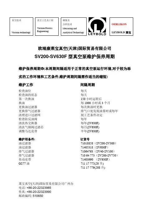
欧瑞康莱宝真空(天津)国际贸易有限公司SV200-SV630F型真空泵维护保养周期维护保养周期 (本周期间隔适用于正常的真空泵运行环境,对于较为恶劣的工作环境和工艺条件,维护周期间隔需作适当的缩短)维护工作间隔周期检查油位每天检查油的状态每天第一次换油150小时运转后换油每1000小时或3个月更换油过滤器每次换油时更换更换排气过滤器排气口处发现油雾时或每年清理进口过滤网视工艺条件决定检查防反油阀每年清洗热交换器每年(SV630F)清洗气镇阀过滤芯每月(SV630F)调整马达皮带半年(SV630F)维护用备件: 订货号油过滤器71018858(SV200-SV300)油过滤器71405318(SV630F)排气过滤器71064763(SV40-SV100)排气过滤器710 64 773(SV200-SV750)传动皮带71403990 (SV630F)GS77油711 17 775(20升)711 17 779(208升)莱宝真空(天津)国际贸易有限公司广州办电话: +86-20-22323985传真: +86-20-22323990邮政编码: 510650欧瑞康莱宝真空(天津)国际贸易有限公司SV200-SV300真空泵维护保养周期维护保养周期 (本周期间隔适用于正常的真空泵运行环境,对于较为恶劣的工作环境和工艺条件,维护周期间隔需作适当的缩短)维护工作间隔周期检查油位每天检查油的状态视工艺条件决定第一次换油150小时运转后换油每1000小时或3个月更换油过滤器每次换油时更换更换排气过滤器排气口处发现油雾或每年清理进口过滤网每月检查防反油阀每年检查浮阀每次更换排气过滤器或每年清理散热油管每年维护用备件: 订货号油过滤器71018858排气过滤器71064763(SV200 4个)71064773(SV300 4个)GS77油711 17 774(5升)711 17 776(25升)711 17 779(208升)欧瑞康莱宝真空(天津)国际贸易有限公司广州维修中心电话: +86-20-22323985传真: +86-20-22323990邮政编码: 510663莱宝真空(天津)国际贸易有限公司SV40-SV100真空泵维护保养周期维护保养周期 (本周期间隔适用于正常的真空泵运行环境,对于较为恶劣的工作环境和工艺条件,维护周期间隔需作适当的缩短)维护工作间隔周期检查油位每天检查油的状态视工艺条件决定第一次换油150小时运转后换油每500-1000小时或6个月更换油过滤器每次换油时更换更换排气过滤器排气口处发现油雾或每年清理进口过滤网每月检查防反油阀每年维护用备件: 订货号油过滤器71212718(SV40-SV65 1个)71213158(SV100 1个)排气过滤器71064763(SV40、SV65 1个)(SV100 2个)GS32油71117723(2升)71117724(5升)71117727(60升)GS77油711 17 774(5升)711 17 776(25升)711 17 779(208升)莱宝真空(天津)国际贸易有限公司中国天津市北辰经济开发区双海道与双辰西道交口电话: +86-22-26970808传真: +86-22-26972017邮政编码: 300400。
莱宝产品手册
莱宝油封式真空泵油品使用说明
莱宝油封式真空泵油品使用说明目录1.真空泵油的作用及性能要求2.莱宝真空泵油品牌及常用牌号3.真空泵油的选择、使用、更换及储存4.油的状态判定5.废油的处理1.真空泵油的作用及性能要求油封式旋转真空泵的泵油,必须符合相关要求。
作为一种运行介质,泵油在真空泵中起着以下重要作用:l密封---防止大气进入排气阀,有相对运动零件间间隙密封(转子与定子、旋片与转子槽等)。
l润滑---相对运动件间的润滑。
l冷却---油在泵内与油箱间循环,散热、冷却。
l液体活塞---填充空隙。
真空泵油的性能要求:l高温下饱和蒸汽压要低,易挥发成分要少。
l最低的水含量和吸水性。
l要有一定粘度,且随温度变化小(粘度温升曲线平滑)。
l润滑性能好,机械应力下具有良好的抗裂解性。
l抗腐蚀、抗氧化、化学性能稳定。
对大部分应用,莱宝真空泵使用Oerlikon Leybold Vacuum品牌的标准油品, 油品牌号为N62, GS32, GS77, FM32, FM68等,具有适宜的化学稳定性和热稳定性,耐水解,与密封材料的相容性很好。
针对一些特殊应用,标准油品的某些弱点表现为:l高温时的稳定性较差。
l化学反应(酸、碱、卤素)的惰性较差。
l遇强氧化剂时(氧气)的惰性较差。
l对非极性物质(蜡、油脂)的溶解性较差。
l对极性物质(低聚物、树脂、分解产物、特别是结晶物)和聚合物的溶解性较差。
因此在特殊应用中,可以使用一些泵适用的特殊润滑品做工作液,或者在泵油中调入添加剂以增强某方面的性能表现。
但须注意,添加剂可能会使泵油的真空表现达不到期望值,如真空度变差,甚至与抽排气体发生反应。
因此如果使用未经审验的油品,可能造成换油频繁,真空性能降低,油反应产生沉淀,甚至损坏泵。
3.真空泵油的选择、使用、更换及储存3.1 使用指定油品:本文中介绍的Oerlikon Leybold Vacuum品牌的标准油品,以及欧瑞康莱宝真空泵产品样本中所提到的油品,都是在我们工厂实验室内,对相应系列的各种泵,在各种使用条件下经过全面长期运行检验后定型的油品。
莱宝双级油封式旋片真空泵
抽 速
真空度
抽 速
真空度
当泵停止时,泵轴上的离心开关开启放空管道,将大气空气送入防返油阀的活 塞下,使防返油阀的阀盘压住进气口,将通向真空容器的管道封闭,将空气放 入泵中。 泵上的油位观察窗便于检查油位,供应的标准泵型备有单相或三相交流电机两 种。
1.2 供货没备
交货时,泵的小型法兰连接口是封闭的,标准设备供货时带有两个肩环和两个 卡箍(DN25KF 或DN40KF ) ,以便于连接进气和排气管道。
注:
1)此值由电容薄膜真空计测得。如用皮拉尼真空计测量,此值会高半个至一个数量级,此值来源于N62油。如采用其它泵油,请 与我们联系。 2)此值为三相泵的噪音,单相泵的噪音会略高。 3)选择不同的电机,泵的总长度a会略有变化。 4)其它电压、频率的电机可根据您的要求而另行配备。 5)无石棉。
GA01.800_011_02 - 11/2009 - © Oerlikon Leybold Vacuum 9
TRIVAC® C
D8C, D16C, D30C, D40C, D60C
双级油封式旋片真空泵
使用说明书 GA01.800_011_02
产品号: 310 18 310 86 311 08 311 59 311 58 及其改型
目录
页
重要安全信息
4
1 说明
5
1.1 工作原理
5
1.2 供货设备
6
1.2.1 带单相交流电机的泵
说明
GA01.800_011_02 - 11/2009 - © Oerlikon Leybold Vacuum 5
说明
1 泵体 2 转子 3 定位销 4 进气通道 5 防返油阀 6 尘粒过滤网 7 进气口 8 气镇阀帽 9 排气口 10 二次空气注入口(消音) 11 油过滤器 12 排气阀 13 排气通道 14 气镇通道 15 进油嘴 16 叶片
莱宝真空泵维护保养说明书
Vacuum technology Vacuum ProcessEngineering分析技术Measuring andAnalyticalTechnologyOERLIKONLEYBOLD莱宝SV200-SV630F型真空泵维护保养周期维护保养周期( 本周期间隔适用于正常的真空泵运行环境,对于较为恶劣的工作环境和工艺条件,维护周期间隔需作适当的缩短) 维护工作间隔周期检查油位每天检查油的状态每天第一次换油150小时运转后换油每1000小时或3个月更换油过滤器每次换油时更换更换排气过滤器排气口处发现油雾时或每年清理进口过滤网视工艺条件决定检查防反油阀每年清洗热交换器每年(SV630F)清洗气镇阀过滤芯每月(SV630F)调整马达皮带半年(SV630F)维护用备件: 订货号油过滤器71018858(SV200-SV300)油过滤器71405318(SV630F)排气过滤器71064763(SV40-SV100)排气过滤器710 64 773(SV200-SV750)传动皮带71403990 (SV630F) GS77油711 17 775(20升)711 17 779(208升)Vacuum technology Vacuum ProcessEngineering分析技术Measuring andAnalyticalTechnologyOERLIKONLEYBOLD莱宝SV200-SV300真空泵维护保养周期维护保养周期( 本周期间隔适用于正常的真空泵运行环境,对于较为恶劣的工作环境和工艺条件,维护周期间隔需作适当的缩短)维护工作间隔周期检查油位每天检查油的状态视工艺条件决定第一次换油150小时运转后换油每1000小时或3个月更换油过滤器每次换油时更换更换排气过滤器排气口处发现油雾或每年清理进口过滤网每月检查防反油阀每年检查浮阀每次更换排气过滤器或每年清理散热油管每年维护用备件: 订货号油过滤器71018858排气过滤器71064763(SV200 4个)71064773(SV300 4个)GS77油711 17 774(5升)711 17 776(25升)711 17 779(208升)Vacuum technology Vacuum ProcessEngineering分析技术Measuring andAnalyticalTechnologyOERLIKONLEYBOLD莱宝SV40-SV100真空泵维护保养周期维护保养周期( 本周期间隔适用于正常的真空泵运行环境,对于较为恶劣的工作环境和工艺条件,维护周期间隔需作适当的缩短) 维护工作间隔周期检查油位每天检查油的状态视工艺条件决定第一次换油150小时运转后换油每500-1000小时或6个月更换油过滤器每次换油时更换更换排气过滤器排气口处发现油雾或每年清理进口过滤网每月检查防反油阀每年维护用备件: 订货号油过滤器71212718(SV40-SV65 1个)71213158(SV100 1个)排气过滤器71064763(SV40、SV65 1个)(SV100 2个) GS32油71117723(2升)71117724(5升)71117727(60升)GS77油711 17 774(5升)711 17 776(25升)711 17 779(208升)Vacuum technology Vacuum ProcessEngineering分析技术Measuring andAnalyticalTechnologyOERLIKONLEYBOLD莱宝RUV AC 真空泵维护保养周期维护保养周期( 本周期间隔适用于正常的真空泵运行环境,对于较为恶劣的工作环境和工艺条件,维护周期间隔需作适当的缩短) 维护工作间隔周期检查油位每天检查油的状态视工艺条件决定第一次换油500小时运转后换油每3000小时清理进口过滤网视工艺条件决定清理泵腔视工艺条件决定更换整套密封件每2-3年维护用备件: 订货号N62 Oil 17701(1升)17702(5升)17701(20升)17701(208升)经销商:深圳市凯福机电设备有限公司电话: +86-755-28926851传真: +86-755-89302180邮政编码: 510663。
莱宝油封式真空泵泵油使用说明
莱宝油封式真空泵油品使用说明目录1.真空泵油的作用及性能要求2.莱宝真空泵油的种类(品牌油牌号)---- 标准油品和特种油品3.真空泵油的选择、使用、更换及储存 4.油的状态判定5.废油的处理1.真空泵油的作用及性能要求油封式旋转真空泵的泵油,必须符合相关要求。
作为一种运行介质,泵油在真空泵中起着以下重要作用:z密封---防止大气进入排气阀,有相对运动零件间的间隙密封(转子与定子、旋片与转子槽等)。
z润滑---相对运动件间的润滑,降低磨损。
z冷却---油在泵内与油箱间循环,散热、冷却。
z携裹---将磨损产生的尘粒或其它颗粒挟裹在油中,减小磨损伤害。
z保护---形成保护性油膜,避免水及化学蒸汽凝结物腐蚀泵内部件。
真空泵油的性能要求:z高温下饱和蒸汽压要低,易挥发成分要少。
z最低的水含量和吸水性。
z要有一定粘度,且随温度变化小(粘度温升曲线平滑)。
z润滑性能好,机械应力下具有良好的抗裂解性。
z抗腐蚀、抗氧化、化学性能稳定。
对大部分应用,莱宝真空泵使用Oerlikon Leybold Vacuum品牌的标准油品, 油品 牌号为N62, GS32, GS77, FM32, FM68等,具有适宜的化学稳定性和热稳定性,耐水解,与密封材料的相容性很好。
针对一些特殊应用,标准油品的某些弱点表现为:z高温时的稳定性较差。
z化学反应(酸、碱、卤素)的惰性较差。
z遇强氧化剂时(氧气)的惰性较差。
z对非极性物质(蜡、油脂)的溶解性较差。
z对极性物质(低聚物、树脂、分解产物、特别是结晶物)和聚合物的溶解性较差。
因此在特殊应用中,可以使用一些泵适用的特殊润滑品做工作液,或者在泵油中调入添加剂以增强某方面的性能表现。
但须注意,添加剂可能会使泵油的真空表现达不到期望值,如真空度变差,甚至与抽排气体发生反应。
因此如果使用未经审验的油品,可能造成换油频繁,真空性能降低,油反应产生沉淀,甚至损坏泵。
3.真空泵油的选择、使用、更换及储存3.1 使用指定油品:本文中介绍的Oerlikon Leybold Vacuum品牌的标准油品,以及欧瑞康莱宝真空泵产品样本中所提到的油品,都是在我们工厂实验室内,对相应系列的各种泵,在各种使用条件下经过全面长期运行检验后定型的油品。
莱宝真空泵说明书中文
第3页/共26页
工作原理图
1. 泵缸体 2. 转子 3. 定位销 4. 进气通道 5. 通气/隔离阀(防返油阀) 6. 尘粒过滤网 7. 进气口 8. 气镇阀帽 9. 排气口 10. 二次空气注入口(消音孔) 11. 油过滤器 12. 排气阀 13. 排气通道 14. 气镇通道 15. 注油口 16. 叶片
第12页/共26页
影响极限真空的因素
• 极限真空(有害空间的存在) 有害空间: 转子与泵腔的接触点到排气口之间的尖角地带,藏在这里并处于排气压强下不能被旋片推出泵腔之外的
气体,常被旋片通过间隙挤到吸入腔内,因而降低泵的极限真空。 旋片与转子、旋片与泵腔的接触点,这里的气体会因为压差的原因影响泵的极限真空。 真空泵油的作用就是填充有害空间以消除其对极限真空的影响。
中间辅助排气阀的设定
在双级泵中,若高真空级与低真空级之间是不等腔的结构(只是泵腔长度不 同),则需在两级中间通道上设置辅助排气阀。
原理图:
第15页/共26页
设定中间辅助排气阀的原因
举例说明:假设高真空级泵腔容积V1为低真空级泵腔容积V2的四倍,由于 是同轴旋转,故高真空级的抽速S1为低真空级抽速S2的四倍。由气体流量连续 性方程可知:P1S1=P2S2,又因S1/S2=4,所以P2/P1=4。由此看出,当高真 空级吸入压强P1为大气压时,其排气压强P2可达4个大气压,此时真空泵就变 成压气机了。由于真空泵配用的电机功率比压缩机小,因而工作困难。
第17页/共26页
Trivac C 极限真空的测定及合格标准
• 全压强:CTR90电容薄膜规+DM21显示器 开气镇Pul≦6E-3mbar 关气镇Pul≦3E-3mbar
• 分压强:ITR100热阴极溅射离子计(B-A规)+IT23显示器+液氮冷阱 关气镇Pul≦4E-4mbar
莱宝真空泵-DOT25 DOT16使用说明书
TRIVAC ®B - DOTRotary Vane Vacuum Pump S 4B -DOT D 8B -DOTD 16B -DOT/-with float switch D 25B -DOT D 40B -DOT D 65B -DOTCat.No.104 04114 06114 10AccessoriesAF/AK 4-8-DOTAF/AK 16-25-DOT AF/AK 40-65-DOT AF/AK 40-65-DOT AR 4-8-DOTFloat switch 16 - 25Operating Instructions Spare Parts ListT R IV A C -B -D O T p um p s a n d a cc e s s o r ie s a r e e q u i pp e d w i t h s p e c i a l s e a l s w h i c h a r e c a p a b l eo f r e s i s t i n g e x p o s u r et o b r a k e f l u i d s .T h e s e pu m p s m u s t o n l y b e o p e r a t e d w i t h b r a k e f l u i d s i n a c c o r d a n c e w i t h D O T 3 a n d D O T 4 o r a l t e r n a t i v e o p e r a t i n g a g e n t s w h i c h h av e b e e n a p p r o v e d b y L e y b o l d .GA/ET 01.208/3.02 - 06/97Contents2Contents. . . . . . . . . . . . . . . . . . . . . . . . . . . . . . . .Page 1Description . . . . . . . . . . . . . . . . . . . . . . . . . .31.1Function . . . . . . . . . . . . . . . . . . . . . . . . . . . . .31.2Supplied equipment . . . . . . . . . . . . . . . . . . . .51.3Accessories . . . . . . . . . . . . . . . . . . . . . . . . . .61.4Transportation . . . . . . . . . . . . . . . . . . . . . . . .61.5Technical data . . . . . . . . . . . . . . . . . . . . . . . .72Operation . . . . . . . . . . . . . . . . . . . . . . . . . . .92.1Installation . . . . . . . . . . . . . . . . . . . . . . . . . . .92.2Connection to the system . . . . . . . . . . . . . . . .92.3Electrical connection . . . . . . . . . . . . . . . . . . .102.4Start-up . . . . . . . . . . . . . . . . . . . . . . . . . . . .112.5Operation . . . . . . . . . . . . . . . . . . . . . . . . . . .122.6Switching off/shutdown . . . . . . . . . . . . . . . . .123Maintenance . . . . . . . . . . . . . . . . . . . . . . . .133.1Checking the oil level . . . . . . . . . . . . . . . . . .143.2Oil change . . . . . . . . . . . . . . . . . . . . . . . . . .143.3Cleaning the dirt trap . . . . . . . . . . . . . . . . . .143.4Removing and fitting the internal demister . . .153.5Disassembly and reassemblyof the electric motor . . . . . . . . . . . . . . . . . . .163.6Replacing the outer shaft seal . . . . . . . . . . . .173.7Removing and remounting the pump module 183.8Leybold service . . . . . . . . . . . . . . . . . . . . . .183.9Storing the pump . . . . . . . . . . . . . . . . . . . . .193.10Maintenance plan . . . . . . . . . . . . . . . . . . . . .204Troubleshooting . . . . . . . . . . . . . . . . . . . . .225Spare parts list . . . . . . . . . . . . . . . . . . . . . .25EEC Declaration of Conformity . . . . . . . . .24Indicates procedures that must be strictlyobserved to prevent hazards to persons.Indicates procedures that must strictly be observed to prevent damage to, or destruc-tion of the equipment.FiguresThe references to figures, e.g.(1/2) consist of the Fig.No.and the Item No.in that order.Leybold ServiceIf a pump is returned to Leybold, indicate whether the pump is free of substances damaging to health or whether it is contaminated.If it is contaminated also indicate the nature of the hazard.Leybold must return any pumps without a "Declaration of Contamination" to the sender's address.Information on the pump’s operating agentThe operating agent used in the pump complies with the US standard FMVSS/116 DOT 4.Operating agents which comply with this specification may be used instead of DOT 3 and may also be mixed with DOT 3.• Store the operating agent only in its origi-nal container in a clean and dry place.Keep the container firmly sealed.• Any contamination by dirt, water, crude oil products or other materials may result in damage to the pump.• Operating agent which has been used must never be re-used.• The operating agent will attack (dissolve)paint.• When swallowing the operating agentthere is the danger of being poisoned.• Always keep the operating agent in a sea-led container and out of reach of children.Disposal of waste oilUnder the amended law relating to waste disposal dated November 1, 1986 (valid in the Federal Republic of Ger-many) the disposal of used oil is subject to new provi-sions.According to legislation relating to waste disposal the so-called principle of causality is applied.Hence,anyone in possession of used oil is responsible for its proper disposal.Used oils coming from vacuum pumps must not be mixed with other substances.Used operating agents must be disposed of separately and in accordance with the regulations.Operating agents from vacuum pumps that have been contaminated by other substances must be labelled, sto-red and disposed of as special waste with reference to the kind of contamination.Waste disposal key:+ 55256 xIn many countries proof of were the operating agent has finally been left is required by Law and often shipping of such contaminated waste requires permission by the authorities.Waste disposal information is available through:Bundesamt für Gewerbliche Wirtschaft (BAW)Frankfurter Str.29-31D-65760 Eschborn/T aunus Phone:+ 49 (0)6196 4041T elefax:+ 49 (0)6196 404212Warning CautionWarning CautionGA/ET 01.208/3.02 - 06/97Description31DescriptionTRIVAC-B-DOT pumps are oil-sealed rotary vane pumps having either a single stage or two stages.The number in the type designation indicates the pumping speed in m 3x h -1.TRIVAC-B-DOT pumps can pump gases and vapours.They are used to evacuate brake systems and to degas hydraulics liquids.The drive motor of the TRIVAC-B-DOT is directly flanged to the pump at the coupling housing.The pump and motor shafts are directly connected by a flexible cou-pling.The bearing points of the pump module are force lubricated sliding bearings.All controls as well as the oil-level glass and the nameplate are arranged on the front.All connections are to be found at the sides of the pump.The oil-level glass is provided with prisms for better observation of the oil level.The pump module consists of assembly parts which are pin-fitted so as to allow easy disassembly and reassem-bly.The pump module can be easily removed without special tools.TRIVAC-B-DOT pumps are equipped with special seals capable of resisting brake fluids.1.1FunctionThe rotor (2/7), mounted eccentrically in the pump hou-sing (2/6), has two radially sliding vanes (2/5) which divi-de the pump chamber into several compartments.The volume of each compartment changes periodically with the rotation of the rotor.As a result, gas is sucked in at the intake port (2/1).The gas passes through the dirt trap sieve (2/2), flows past the open anti-suckback valve (2/3) and then enters the pump chamber (2/6).In the pump chamber, the gas is passed on and compressed, after the inlet aperture is closed by the vane.The operating agent injected into the pump chamber is used for sealing and lubricating.The slap noise in the pump which usually occurs when attaining the ultimate pressure is prevented by admitting a very small amount of air into the pump chamber.The compressed gas in the pump chamber is ejected through the exhaust valve (2/10).The operating agent entrained in the gas is coarsely trapped in the internal demister (2/11);there the operating agent is also freed of mechanical impurities.The gas leaves the TRIVAC-B-DOT through the exhaust port.During compression, a controlled amount of air - the so-called gas ballast - can be allowed to enter the pump chamber by opening the gas ballast valve.The gas bal-last stops condensation of vapours in the pump chamber up to the limit of water vapour tolerance as specified in the technical data for the pump.CautionGA/ET 01.208/3.02 - 06/97The gas ballast valve is opened and closed by turning the gas ballast knob (7/5) on the front.T o enable the TRIVAC-B-DOT to be used at intake pres-sures as high as 1,000 mbar, a special lubricating system was developed featuring force-lubrication of the sliding bearings.A pump (3/6) for the operating agent pumps the opera-ting agent from the reservoir (3/5) into a pressure-lubri-cation system which supplies all bearing points (3/2).From there the operating agent enters the pump cham-ber area (2/6) of the vacuum pump.The pump for the operating agent is fitted in the front end plate on the coupling side of the pump module.The suc-tion line for the operating agent is placed low, resulting in a large usable reservoir.The operating agent is separated from the gas in the TRIVAC-B-DOT in two steps as described above.First,small droplets are coalesced into large drops in the inter-nal demister (2/11) fitted above the exhaust valve (2/10).These are then returned by deflection at the chamber wall of the volume for the operating agent back to the reservoir for the operating agent.This and the large usa-ble reservoir for the operating agent ensure long inter-vals between operating agent changes even at high inta-ke pressures.DescriptionThe vacuum is maintained by the TRIVAC-B-DOT by an integrated hydropneumatic anti-suckback valve (2/3)which is controlled via the pressure of the operating agent.During operation of the TRIVAC-B-DOT the control piston (4/3) remains sealed against a spring (4/2) by the pressure of the operating agent.The valve disc (4/6) of the anti-suckback valve is held at the lower position by its own weight (valve open).When the pump stops (becau-se it has been switched off or because of a failure), the pressure of the operating agent drops and the spring (4/2) presses the control piston (4/3) up.Thus a connec-tion is provided between the case for the operating agent or the reservoir (4/1) for the operating agent and the piston (4/4) of the anti-suckback valve.Due to the pres-sure difference between the case of the operating agent and the intake port, the operating agent presses the piston (4/4) up and the valve plate (4/6) against the valve seat (4/5).The quantity of operating agent in the reser-voir (4/1) prevents the entry of air into the intake port (2/1) at the beginning of this process.After the operating agent has flowed out from the reser-voir and when the valve plate rests on the valve seat, air follows in, which vents the pump chamber and forces the valve disc (4/6) against its seat.This effectively prevents backstreaming of any operating agent or its vapours.The anti-suckback valve (2/3) operates independently of the operating mode of the pump, i.e.also with gas ballast.4GA/ET 01.208/3.02 - 06/97Description1.2Supplied EquipmentThe TRIVAC-B-DOT is delivered with the following basic equipment:•Pump with all-metal motor;all external plastic parts have been replaced by metal parts,• Pump filled with brake fluid according to DOT 4,• 1 centering ring,• 1 centering ring with dirt trap, • 2 clamping rings.As protection during shipment, the connection ports are each blanked off by shipping seals.5TRIVAC-B-DOT pumps with single-phase AC motor are supplied ready to operate with switch, built-in thermal motor protection switch, mains cable (2 m) and mains plug.For TRIVAC-B-DOT pumps with three-phase AC motor,the switch, motor protection switch, mains cable etc.are not included.Fig.4 Hydropneumatic anti-suckback valveKey to Fig.41Reservoir for the operating agent 2Spring 3Control piston 4Anti-suckback piston5Valve seat 6Valve disk 7Gas inletDescription1.3AccessoriesCat.No. Exhaust filter AF 16-25 DOT . . . . . . . . . . . . . . .124 16 Exhaust filter AF 4-8 DOT . . . . . . . . . . . . . . . . .124 14Condensate trap AK 16-25 DOT . . . . . . . .upon request Condensate trap AK 4-8 DOT . . . . . . . . . .upon request Exhaust filter AF 40-65 DOT . . . . . . . . . .upon request AR 16-25 DOT . . . . . . . . . . . . . . . . . . . . .upon request Float switch for all models . . . . . . .Ref.No.200 39 838 FE 40 - 65 for AF 40 - 65 . . . . . . . .Ref.No.200 39 840Only use the kind of operating agent speci-fied by Leybold.Alternative types of opera-ting agent are specified upon request.1.4Transportation•Pumps which are filled with operatingagent must only be moved while standingupright.Otherwise operating agent mayescape.Avoid any other orientations during trans-port.• Check the pump for the presence of anyoperating agent leaks, since there existsthe danger that someone may slip on spiltoperating agent.• When lifting the pump you must make useof the crane eyes provided on the pumpfor this purpose;also use the recommen-ded type of lifting device.6GA/ET 01.208/3.02 - 06/97 CautionCautionWarningGA/ET 01.208/3.02 - 06/97Description7* as per DIN 28 400 and following numbers1)Weight for the version with three-phase motor220-240/380-420 V , 50 Hz 240-265/415-460 V , 60 Hz1.5Technical DataWe can only guarantee that the pump will meet its specifications when using the type of lubricant which has been specified by us.CautionGA/ET 01.208/3.02 - 06/97Description8Operation2.1InstallationTRIVAC-B-DOT pumps must only be ope-rated in connection with brake fluid fil-ling and degassing systems.The TRIVAC-B-DOT pump can be set up on a flat, hori-zontal surface.Rubber feet under the coupling housing ensure that the pump can not slip.If you wish firmly install the TRIVAC-B-DOT in place, ins-ert bolts through bore holes in the rubber feet.Max.tilt for the pump (without furtherattachment) with possibly fitted standardaccessories is 10°from the vertical.The rubber feet act as vibration absorbers.They must therefore not be compressed byscrews.When installing the TRIVAC-B-DOTpump, make sure that the connections andcontrols are readily accessible.The site chosen should allow adequate aircirculation to cool the TRIVAC-B-DOT (keepfront and rear unobstructed).The ambienttemperature should not exceed+ 40 °C (104 °F) and not drop below+ 12 °C (55 °F) (see Section 2.5.3).The max.amount of heat given off approxi-mately corresponds to the rated motorpower.2.2Connection to theSystemBefore connecting the TRIVAC-B-DOT, remove the ship-ping seals from the connection flanges (7/2) and (7/3).Retain the shipping seals in case you needto store the pump in the future.The pump is shipped with intake and exhaust flanges mounted for horizontal connection of the connecting lines.Y ou can easily convert the ports for vertical connection by removing the four capscrews, rotating the flanges as required, and reinstalling the capscrews. Connect the intake and exhaust lines with a centering ring and a clamping ring e the centering ring with the dirt trap for the intake port.Connect the intake and exhaust lines using anti-vibration bellows, without placing any strain on the pump.The intake line must be clean.Deposits in the intake line may outgas and adversely affect the vacuum.The connecting flanges must be clean and undamaged. The maximum throughput of the pump is equivalent to the pumping speed of the pump (see Section 1.5).92OperationCaution CautionCautionGA/ET 01.208/3.02 - 06/97OperationThe cross-section of the intake and exhaust lines should be at least the same size as the connection ports of the pump.If the inta-ke line is too narrow, it reduces the pumping speed.If the exhaust line is too narrow,overpressures may occur in the pump;this might damage the shaft seals and cause leaks.The maximum pressure in the case for the operating agent must not exceed 1.5bar (absolute).When pumping vapours, it is advisable to install condensate traps on the intake and exhaust sides.Install the exhaust line with a downward slope (lower than the pump) so as to pre-vent condensate from flowing back into the pump.If this is not possible, insert a con-densate trap.The exhaust gases from the vacuum pump must be safely led away and subjected to post-treatment as required.In order to redu-ce the emission of operating agent vapours we recommend the installation of an addi-tional exhaust filter (Leybold accessory).Depending on the type of application or the kind of pumped media, the corresponding regulations and information sheets must be observed.Never operate the pump with a sealedexhaust line.There is the danger of injury.The exhaust gases coming from the vacu-um pump must be lead away safely and subjected to suitable post treatment as required.Before starting any work on the pump, the personnel must be informed about possible dangers first.All safety regulations must be observed.2.3Electrical ConnectionBefore wiring the motor or altering thewiring, ensure that mains supply for the pump is off and that it can not be applied inadvertently.In order to prevent the pump from running up unexpectedly after a mains power failu-re, the pump must be integrated in the con-trol system in such a way that the pump can only be switched on again manually.This applies equally to emergency cut-out arran-gements.Electrical connections must only be done by a qualified electrician as defined by VDE 0105 in accordance with the VDE 0100 gui-delines.Observe all safety regulations.TRIVAC-B-DOT pumps are available with a single-phase or a three-phase AC motor.2.3.1Pump with Single-Phase AC MotorPumps equipped with a single-phase AC motor may be connected directly to the mains via the mains cord and the mains plug.At 230 V use at least a 6 A slow-blow or a 10 A fast-blow fuse.The direction of rotation need not be checked as it is fixed.The motor is protected against overloading by a thermal overload switch with automatic resetting.If the thermal overload protector shuts offthe pump, the motor will restart itself as soon as it cools.That's why the mains plug should be disconnected from the mains before starting with any work on the pump.2.3.2Pump with Three-Phase AC MotorTRIVAC-B-DOT pumps with a three-phase motor are supplied without accessories for electrical connection.They must be connected via the appropriate cable, and a suitable motor protection switch.Set the switch in accordance with the rating on the motor nameplate.Fig.8 shows the connection for pumps with 230/400 V ,50 Hz motors.Please also observe the motor wiring dia-gram in the junction box and the information given on the nameplate of the motor.10GA/ET 01.208/3.02 - 06/97Warning Warning CautionWarningOperation After connecting the motor and after everytime you alter the wiring, check the directionof rotation.To do so, briefly switch on themotor and check whether a suitable cover(e.g.a blank flange) is sucked in at the inta-ke port.If not, interchange two phases ofthe connection.Observe the direction arrow on the couplinghousing.2.4Start-upTRIVAC-B-DOT pumps must only be ope-rated in connection with brake fluid fil-ling and degassing systems.Do not select a degassing pressure of lessthan 1 mbar, since at this pressure volatilesubstances in the brake fluid may escapeand damage the elastomer seals of thepump.Each time before starting up check the level of the ope-rating agent.For pumps with 3-phase motors, check the direction ofrotation before starting the pump for the first time andafter each change in the electrical connection (see Sec-tion 2.3.2).On initial start-up, after prolonged idle periods or afterhaving changed the operating agent, the specified ulti-mate pressure cannot be attained until the operatingagent has been degassed.This can be done by runningthe pump for approx.30 min.with the intake line closedand the gas ballast valve (7/5) open.Before starting the pump ensure that thepump and the fitted accessories meet therequirements of your application and thatsafe operation can be guaranteed.Avoid exposure of any part of the body tothe vacuum.There is the danger of injury.Never operate the pump with an open inta-ke port.Vacuum connections as well as oil-fill and oil-drain openings must never beopened during operation.The safety regulations which apply to theapplication in each case must be observed.This applies to installation, operation andduring maintenance (service) as well aswaste disposal and transportation.The standard pump is not suited for pum-ping of hazardous gases or vapours.Our technical sales department is available for furtheradvice in these matters.2.4.1Areas of ApplicationThe pump is not suitable for pumping of:- ignitable and explosive gases or vapours,- oxidants,- pyrophorous gases.The pumps are not suitable for pumping ofliquids or very dusty media.Suitable protec-tive devices must be installed.Our technical sales department is available for furtheradvice in these matters.8 Connection diagram for TRIVAC-B-DOT with 50 Hz 3-phase motorDelta connection Star connectionCautionWarningWarningCautionWarningCautionOperation2.5OperationTRIVAC-B-DOT pumps can pump condensable gases and vapours, provided that the gas ballast valve (7/15) is open and the pump has attained its operating tempera-ture.2.5.1Pumping of Non-CondensableGasesIf the process contains mainly permanent gases, the pump may be operated without gas ballast, provided that the saturation vapour pressure at operating temperature is not exceeded during compression.If the composition of the gases to be pumped is not known and if condensation in the pump cannot be ruled out, run the pump with the gas ballast valve open in accordance with Section 2.5.2.2.5.2Pumping of Condensable Gases andVapoursWith the gas ballast valve open and at operating tempe-rature, TRIVAC-B-DOT pumps can pump pure water vapour up to the water vapour tolerance specified by the technical data.If the vapour pressure increases above the permissible level, the water vapour will condense in the oil of the pump.When pumping vapours ensure that the gas ballast valve is open and that the pump has been warmed up for approximately 30 minutes with the intake line closed.Vapour phases may only be pumped up tothe permissible limit after the pump hasattained its operating temperature.During pumping, vapours may dissolve inthe oil.This changes the properties of theoperating agent and thus there is a risk ofcorrosion in the pump.Therefore, don'tswitch off the TRIVAC-B-DOT immediatelyafter completion of the process.Instead,allow the pump to continue operating withthe gas ballast valve open and the intakeline closed until the operating agent is freeof condensed vapours.We strongly recom-mend operating the TRIVAC-B-DOT in thismode for about 30 minutes after completionof the process.In cyclic operation, the TRIVAC-B-DOT should not be switched off during the intervals between the individual working phases (power consumption is minimal when the pump is operating at ultimate pressure), but should continue to run with gas ballast valve open and intake port closed (if possible via a valve).Once all vapours have been pumped off from a process (e.g.during drying), the gas ballast valve can be closed to improve the attainable ultimate pressure.2.5.3Operating TemperatureProper operation of the TRIVAC-B-DOT is ensured in the ambient temperature range between 12 °C to 40 °C (55°F to 104 °F).At operating temperature, the surface temperature of the TRIVAC-B-DOT may lie between 40 °C and over 80 °C (104 °F and 176 °F), depending on the load.The surface temperature of the TRIVAC-B-DOT pumps may rise above 80 °C.There isthe danger of receiving burns.2.6Switching Off/ShutdownUnder normal circumstances, all that you need do is to electrically switch off the TRIVAC-B-DOT.For longer standstill periods you must sealthe pump so that no humidity can enterbecause brake fluid is hygroscopic.No further measures will be required.When pumping condensable media let the pump conti-nue to operate with the gas ballast valve open and the intake line closed before switching off (see Section 2.5.2).When pumping aggressive or corrosive media, let the pump continue to operate even during long non-working intervals (e.g.overnight) with the intake line closed and the gas ballast valve open.This avoids corrosion during idle periods.If the TRIVAC-B-DOT is to be shutdown for an extended period after pumping aggressive or corrosive media or if the pump has to be stored, proceed as follows:After pumping of pumping harmful sub-stances, take adequate safety precautions. Our technical sales department is available for further advice in this matter.WarningWarningCautionCautionMaintenanceDrain the operating agent (see Section 3.2).Add clean operating agent until the level is at the "min"mark (see Section 3.2) and let the pump operate forsome time.Then drain the operating agent and add clean operating agent until the level is at the "max" mark (see Section 3.2).Seal the connection ports.Special conservation or anti-corrosion oils aren't necessary.Please also take note of the informationgiven in Section 3.9 (Storing the Pump). 2.6.1Shut-Down through MonitoringComponentsWhen the pump has been switched off dueto overheating sensed by the motor coil pro-tector, the pump must only be startedmanually after the pump has cooled downto the ambient temperature and after havingremoved the cause first.2.6.2Failure of the Control System or theMains PowerIn order to prevent the pump from runningup unexpectedly after a mains power failu-re, the pump must be integrated in the con-trol system in such a way that the pump canonly be switched on again manually.Thisapplies equally to emergency cut-out arran-gements.3MaintenanceDisconnect the electrical connections befo-re disassembling the pump.Make absolute-ly sure that the pump cannot be acciden-tally started.If the pump has pumped harmful sub-stances, contrary to what has been statedin Section 2.4, ascertain the nature ofhazard and take adequate safety measu-res.Observe all safety regulations.If you send a pump to LEYBOLD for repair please indi-cate any harmful substances existing in or around thepump.A form is available from LEYBOLD for this purpo-se.When disposing of used oil, you mustobserve the applicable environmental regu-lations!Due to the design concept, TRIVAC-B-DOT pumpsrequire very little maintenance when operated under nor-mal conditions.The work required is described in thesections below.In addition to this, a maintenance plan isprovided in Section 3.10.All work must be carried out by suitably trai-ned personnel.Maintenance or repairs car-ried out incorrectly will affect the life andperformance of the pump and may causeproblems when filing warranty claims.Formore information please contact the Ley-bold Service.If the TRIVAC-B-DOT is used in ambient airwhich is much contaminated, make surethat the air circulation and the gas ballastvalve are not adversely affected.CautionCautionCautionWarningWarningWarningMaintenance3.1Checking the Oil Level During operation of the TRIVAC-B-DOT the level of the operating agent must always remain between marks (9/2) and (9/3) on the level glass.The amount of opera-ting agent must be checked and topped up as required.Fill in operating agent only after the pumphas been switched off.3.2Oil ChangeFor proper operation of the pump, it is essential that the pump has an adequate supply of the correct and clean operating agent at all times.The operating agent must be changed when it looks dirty or if it appears chemically or mechanically worn out. The operating agent should be changed after the first 100 operating hours and then at least every 2,000 to 3,000 operating hours or after one year.At high intake pressures and intake temperatures and/or when pum-ping contaminated gases, the operating agent will have to be changed much more frequently.Further changes of the operating agent should be made before and after long-term storage of the pump.If the operating agent becomes contaminated too quick-ly, install a dust filter and/or a filter for the operating agent (see Section 1.3).Contact us for more information in this matter.Only change the operating agent after thepump has been switched off and while thepump is still warm.Required tool:Allen key 8 mm.Remove the drain plug (9/4) for the operating agent and let the used operating agent drain into a suitable contai-ner.When the flow of operating agent slows down, screw the drain plug for the operating agent back in, briefly switch on the pump (max.10 s) and then switch it off again.Remove the drain plug for the operating agent once more and drain out the remaining operating agent. Screw the drain plug for the operating agent back in (check the flat gasket and reinstall a new one if neces-sary).Remove the fill plug (9/1) for the operating agent and fill in fresh operating agent.Screw the fill plug (9/1) for the operating agent back in.If there is the danger that the operatingagent may present a hazard in any waybecause of the media which have beenpumped, you must determine the kind ofhazard and ensure that all necessary safetyprecautions are taken.We can only guarantee that the pump ope-rates as specified by the technical data ifthe lubricants recommended by us areused.3.3Cleaning the Dirt TrapA wire-mesh sieve is located in the intake port of the pump to act as a dirt trap for coarse particles.It should be kept clean to avoid a reduction of the pumping speed. For this purpose, remove the dirt trap (2/2) from the inta-ke port and rinse it in a suitable vessel with solvent.Then thoroughly dry it with compressed air.If the dirt trap is defective, replace it with a new one.The cleaning intervals depend on the appli-cation.If the pump is exposed to large amo-unts of abrasive materials, a dust filtershould be fitted into the intake line.9 Exchanging the operating agentKey to Fig.9Plug for filling in the operating agentOperating agent level mark maximumOperating agent level mark minimumPlug for draining out the operating agentCautionWarning 1 2 3 4CautionCautionCaution。
- 1、下载文档前请自行甄别文档内容的完整性,平台不提供额外的编辑、内容补充、找答案等附加服务。
- 2、"仅部分预览"的文档,不可在线预览部分如存在完整性等问题,可反馈申请退款(可完整预览的文档不适用该条件!)。
- 3、如文档侵犯您的权益,请联系客服反馈,我们会尽快为您处理(人工客服工作时间:9:00-18:30)。
GA/ET-02307/8SOGEV ACSV200, SV300 BR2使用说明书(包括备件清单)适用的编号:10926/10927 : J 97 12 00001 (SV200)10930/10931 : J 97 12 00001 (SV300)95526/95527 – (JAPAN) : J 97 12 00001 (SV200)95536/95537 – (JAPAN) : J 97 12 00001 (SV300)95027 – (USA) : J 97 12 00001 (SV200)95031 – (USA) : J 97 12 00001 (SV300)操作说明书备件清单合格证的EC声明我们,LEYBOLD SA,在此郑重声明,以下规定的产品在设计、型号及流通过程中的改型方面均满足有关EEC指令的安全和健康基本要求。
如果没有我们批准而对产品做任何改变,本声明将无效。
产品结构:单级旋片泵SOGEV AC型号:UV25SV 16 – SV 25 – SV 40 – SV 65SV 100 – SV 200 – SV 300 – SV 585SV 630 – SV 750 – SV 1200和它们的改型,但不带电机交付的泵和带Eex…..电机交付的泵除外。
产品满足下述指令要求:- EEC 机械指令(89/392/EWG)和相继指令91/336/EWG- EEC 低电压指令(73/23/EWG)- EEC 电磁兼容性指令(89/336/EWG)应用协调标准:- EN 1012.1 (project 1993)292.1- EN- EN292.260204.1- EN真空泵安装和启动前,必须阅读并弄懂本使用说明书。
注意:按照最新技术标准和安全规程已经制造出SOGEV AC真空泵。
如果不能正确的安装或不能按指导正确使用,会发生危险。
在一定的运行条件下,当运转真空泵时可能出现危险状态。
如果发生这种情况,请与我们当地办事处联系。
警告:表明为防止造成人身伤害必须特别遵守的工艺规程。
当心:表明为防止设备损坏或破坏必须特别遵守的工艺规程。
图:参考图,例如(2/10)在这个括号中是由图号和序号组成的。
我们保留修改本说明书所给设计和任何数据的权利。
不另加说明。
警告:当对泵系统操作时,一定严格遵守本说明书。
在开始任何工作前,设备一定要切断电源。
要采取相应措施,保证泵不能启动。
如果泵已抽过危险气体,绝对必须确定涉及危害的性质并采取相应安全措施。
遵守所有安全规程!在打开吸入口或排出口之前,一定要采取安全措施。
LEYBOLD维修如果需要把泵发往LEYBOLD维修,请说明泵是否会有危害人体健康的物质或说明泵是否已被污染。
如果泵已被污染,还要说明危害的性质。
为此,您必须使用我们印制的表格,该表格按需求提供。
“真空设备和组件污染说明”的复印件复制在本说明书的最后。
请把这个表格附在泵上或把泵与它一起包装。
为了满足法规和保护我们的工作人员,特需此说明。
如果无“污染说明”,LEYBOLD将把收到的泵按发送人地址退回。
警告:泵的包装必须保证:泵在运输中不会损坏,并且不会有有害物质从包装中溢出。
目录使用说明p.51 概述p.51.1 结构与功能p.51.1.1 应用范围p.61.2 标准规格p.61.3 技术数据p.71.3.1 欧洲型号的50Hz和60Hz电机p.71.3.2 技术数据p.71.3.3 USA型号p.81.4 接头p.101.5 附件p.111.6 SV+WAU直联组合p.111.7 备件p.121.8 润滑油1.9 管理与存放p.122 使用p.132.1 安装p.132.2 连接到系统上p.142.2.1 吸入口侧p.142.2.2 排气口侧p.152.3 电气连接p.162.4 启动p.172.5 运行p.182.5.1 抽空非冷凝气体p.182.5.2 抽空可冷凝气体和蒸汽p.182.5.3 循环工作p.192.6 停车p.202.7 真空泵的极限压力p.202.8 安装选用的气镇阀p.213 维修p.213.1 日常维护制度p.223.2 检查油p.223.2.1 油位p.223.2.2 GS77油状态p.233.3 换油,更换油过滤器p.233.4 更换出口过滤器,检查压力安全阀p.243.5 清洗污物防护罩p.253.6 检查防返油阀p.253.7 清洗气镇进口过滤器p.263.8 检查浮球阀p.263.9 更换排气阀p.273.10 更换泵组件p.273.11 拆、装泵组件p.283.12 电机的拆卸p.293.13 冷却盘管清洗p.294 故障排除指南p.30备件清单p.37 警告本手册对标准产品是有效的。
如果交付的泵是特殊型号,则泵还带有附加文件,该文件作为说明书的一部分,操作说明1、概述1.1、结构和功能SOGEV AC SV 200 和 SV300是单级油封式旋片泵。
泵本身带有防返油阀、气镇阀(选用件)、出口过滤器、回油线路和油冷却回路。
泵由直联法兰电机驱动。
注:气镇阀在USA销售的泵中是标准件。
安装在泵缸体(7/83)中的偏心转子(7/88)有三块叶片,它们把泵腔分成几个隔室。
每个隔室的容积随转子旋转周期性改变。
当转子旋转时,抽空腔的进气部分容积扩张,将气体通过吸入口吸入。
气体经过污物防护罩,打开的防返油阀(7/54)进入泵腔。
当转子进一步旋转,叶片从吸入口将泵腔部分分开。
这部分泵腔体积减少,气体被压缩。
气体在略高于大气压力时经过排气阀(6/20)从泵腔中排出。
油被注入泵腔起密封,润滑和冷却泵的作用。
压缩气体夹带的油在油箱(6/27)内由于折转而被初步捕集。
然后在出口过滤器元件(6/29)中被彻底过滤。
于是,排气中油含量下降至低于可见程度(捕集率大于99%)。
在出口过滤器中捕集的油经过回油管(6/11)返回到进气室。
为了防止大气压下的气体从油槽流入进口,回油管由一个浮球阀控制。
油循环是由油箱(压力高于或等于大气压)和泵的进气口(压力低于大气压)之间存在的压差维持的。
一部分油取自油槽(6/27),经过油过滤器(6/25)流到转子的轴承支撑点和泵腔。
注入泵内油的另一部分不会通过油过滤器。
所以,如果油过滤器偶然完全堵塞,通过具有足够油量的第二线路确保润滑,从而保证泵良好机械运转。
然而在这种情况下,泵达不到规定的极限压力。
一般来说这表明油脏了或油过滤器被堵塞了。
在电机轴上旋转的风扇产生冷却所必须的空气流,来通过冷却盘管中的润滑。
根据需求,可订购带气镇装置(6/14)的泵(USA型号的泵气镇阀为标准配置)。
打开气镇阀,让被称作“气镇”的可控制的一定数量的空气进入泵腔。
当抽空可冷凝气体或蒸汽时,这气镇可防止可冷凝气体在泵内的冷凝(最大容许水蒸汽压力见技术参数)。
有不同种类的气镇:- 标准气镇- 较大气镇(10%)- 带电磁阀的气镇见 2.5.2供货时不带气镇阀的泵,也可加装气镇阀。
(参阅第1.5节和第2.8节)用防返油阀(7/54)防止真空腔的意外破空和返油。
1.1.1 应用范围根据设计,SOGEV AC泵可用来抽空稳定气体,其工作范围为从大气压到泵极限真空之间的粗真空范围。
警告SOGEV AC泵不能抽空侵蚀性、腐蚀性的、易爆或易燃气体。
若存在有侵蚀性的,易燃的,腐蚀的或易爆气体,请与LEYBOLD公司联系。
根据设计,这些泵不能在易燃或易爆环境下工作。
若有问题,请与LEYBOLD公司联系。
当心泵不适合抽空液体或含有灰尘的介质。
必须引入相应防护措施。
如有问题,请与LEYBOLD公司联系。
在抽空氧含量高于大气(>20%)的气体或其它高活性气体之前,泵必须改型,除油,然后必须使用特殊油(例如PFPE)。
采取相应安全措施。
请与LEYBOLD联系以获取有关重要的安全说明书。
1.2 标准规格处于备用状态的泵,电机随泵一起提供。
随泵一起提供的还有GS77或等同的油已注入泵内。
连接口由塑料保护盖封住。
在启动泵之前要去除这些塑料保护盖。
1.3 技术数据1.3.1欧洲型号的50Hz 和60Hz 电机。
SV200和SV300的标准型安装的是50/60Hz 电机。
标准电压:在50Hz 下230/400V在60Hz 下460V+10%+10%-6%1.3.2 技术参数表SV200 SV300 50Hz 60Hz 50Hz 60Hz名义抽速 m 3.h -1180 220 280 340 抽速m 3.h -1 170 200 240 290 无气镇1)下的极限分压mbar <8.10-2 <8.10-2 <8.10-2 <8.10-2 有气镇下的极限全压(标准)1) mbar<0.7<0.7<0.7<0.7有气镇下水蒸汽容限(标准)1)mbar 40 50 30 40有气镇下水蒸汽容许负载 kg.h -1 5.7 8.5 5.4 7.4 配大气镇时的耐水蒸气压力 mbar 50 60 60 70配大气镇时的耐水蒸气能力 kg.h -1 5.7 8.5 10 12.5 噪声水平2)dB(A)69737074漏率 mbar.l.s -1<1.10-3 <1.10-3 <1.10-3 <1.10-3电源电压(标准的) V 230/400 460 4) 230/400 460 4) 如需其它电压请与LEYBOLD 接洽 电机功率 kW 44.65.56.3保护类型IP55IP55 3 IP55 IP55 3额定转速min.-1 1450 1750 1450 1750重量(充油状态) kg 160 160 200 200 油量(min 最小/max 最大) l 5/9 5/9 8.5/11.5 8.5/11.5 进气口 G2 G2G2 G2NPT 2 3)NPT 2 3) 排气口 G2 G2 G2 G2NPT 2 3)NPT 2 3)1)符合DIN 28400,有标准气镇2)在无气镇极限压力下运行,距1m 远空地现场测量 3)请与LEYBOLD 联系4)CEI: 460V , NEMA :200-230/460V订货编号SV200 SV300 带有三相电机的泵230V/400V ,50Hz; 460V , 60Hz 10926 10930 带有三相电机和气镇阀的泵230V/400V , 50Hz; 460V , 60Hz 1092710931带有200V ,50/60Hz 三相电机的泵 95526 95536可选件:95390-95391可选排气口øb油位监控器(可选件)气镇阀油过滤器温度开关(可选件)注油口油观察窗排油口排气过滤器进气口 øc1.3.3 US Versions (销向美国产品) 尺寸单位:mm 尺寸单位:mm表中文字真空泵配有气镇阀和NEMA 标准电机200-230/460V AC 60Hz , 3 Phase (+400V 50Hz )排气口法兰 NPT 标准(阴螺纹)进气口法兰 NPT 标准(阴螺纹)注油量(最大/最小) 重量 转速电机功率 有标准气镇下水蒸气容限 有气镇下极限总压(标准)1)无气镇下极限分压1) 抽速1) 名义抽速1) 注: 泵在60Hz 下运转时抽速要比在50Hz 下运转时抽速高出20%。