Pancharatnam-Berry phase optical elements for wavefront shaping in the visible domain switc
基于石墨烯超表面的效率可调太赫兹聚焦透镜
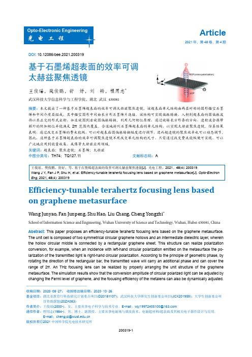
DOI: 10.12086/oee.2021.200319基于石墨烯超表面的效率可调太赫兹聚焦透镜王俊瑶,樊俊鹏,舒 好,刘 畅,程用志*武汉科技大学信息科学与工程学院,湖北 武汉 430081摘要:本文提出了一种基于石墨烯超表面的效率可调太赫兹聚焦透镜。
该超表面单元结构由两层对称的圆形镂空石墨烯和中间介质层组成,其中镂空圆形中间由长方形石墨烯片连接。
该结构可实现偏振转换,入射到超表面的圆偏振波将以其正交的形式出射,如左旋圆到右旋圆偏振转换。
利用几何相位原理,通过旋转长方形条的方向,透射波会携带额外的附加相位并能满足2π范围内覆盖。
合适地排列石墨烯超表面的单元结构,以实现太赫兹聚焦透镜。
仿真结果表明:通过改变石墨烯的费米能级,可以对超表面圆偏振转换幅度进行调节,进而超透镜的聚焦效率也可以动态调节。
因此,这种基于石墨烯超表面的效率可调聚焦透镜不用改变单元结构的尺寸,只需通过改变费米能级便可实现,可以广泛地应用到能量收集、成像等太赫兹应用领域。
关键词:超表面;聚焦透镜;石墨烯;太赫兹中图分类号:TH74;TQ127.11 文献标志码:A王俊瑶,樊俊鹏,舒好,等. 基于石墨烯超表面的效率可调太赫兹聚焦透镜[J]. 光电工程,2021,48(4): 200319Wang J Y , Fan J P , Shu H, et al. Efficiency-tunable terahertz focusing lens based on graphene metasurface[J]. Opto-Electron Eng , 2021, 48(4): 200319Efficiency-tunable terahertz focusing lens based on graphene metasurfaceWang Junyao, Fan Junpeng, Shu Hao, Liu Chang, Cheng Yongzhi *School of Information Science and Engineering, Wuhan University of Science and Technology, Wuhan, Hubei 430081, China Abstract: This paper proposes an efficiency-tunable terahertz focusing lens based on the graphene metasurface. The unit cell is composed of two symmetrical circular graphene hollows and an intermediate dielectric layer, wherein the hollow circular middle is connected by a rectangular graphene sheet. This structure can realize polarization conversion, for example, when an incidence with left-hand circular polarization emitted on the metasurface the po-larization of the transmitted light is right-hand circular polarization. According to the principle of geometric phase, by rotating the direction of the rectangular bar, the transmitted wave will carry an additional phase and can cover the range of 2π. An THz focusing lens can be realized by properly arranging the unit structure of the graphene metasurface. The simulation results show that the conversion amplitude of circular polarized light can be adjusted by changing the Fermi level of graphene, and the focusing efficiency of the metalens can also be dynamically adjusted.LCPRCP(cross-polarization)xy zV g——————————————————收稿日期:2020-08-27; 收到修改稿日期:2020-10-26基金项目:湖北省教育厅科技研究计划重点项目(D2*******);武汉科技大学研究生创新基金项目(JCX201959);大学生创新基金项目资助课题(20ZA083)作者简介:王俊瑶(2000-),女,主要从事电子科学与技术专业。
巴黎欧莱雅“光学嫩肤级”组合新品上市 。

点击图片进入下一页>>左起:Elisabeth Bouhadana、Jo?lle Ciocco、李冰冰、鲍燕悦巴黎欧莱雅品牌总经理鲍燕悦女士,巴黎欧莱雅品牌全球科技传播总监Elisabeth Bouhadana女士及全球顶级护肤专家Jo?lle Ciocco女士亲临现场见证巴黎欧莱雅复颜光学嫩肤组合的上市。
一直以来,巴黎欧莱雅顶尖的研发团队和不断的立异科技,为女性朋友带来一次又一次的护肤革命,复颜光学嫩肤系列的上市更是向我们展示了品牌强盛的研发实力和立异科技。
同时,欧莱雅研发中央开展了一项为期6个月的研究,通过41位女性长达半年的研究发现,在3%高浓度Pro-Xylane玻色因的作用下:眼角的鱼尾纹淡化达11%,肌肤的紧致度增加了24%,肤质得到了全面改善;14天后,肌肤破损处能迅速复原。
美容护肤小窍门,美容护肤知识,美容知识/list-8-1.html。
25岁是女性的黄金岁月,但此时也是女性肌肤的分水岭,过了25岁,肌肤的初老化现象开始发生,细纹泛起、毛孔增大、肌肤失去弹性,如何应付这些突如其来的题目成为了泛博女性的困扰?光学嫩肤作为新兴的美容方式,虽然受到众多女性的追捧,但是其高昂的价格和手术的风险也令人望而生畏。
全套产品持续使用,能匡助肌肤抵御岁月痕迹,全面恢复年青状态!年青肌肤的枢纽——玻色因玻色因,由欧莱雅研发中央经由14年精心研究而成,它能促进透明质酸的天生以及胶原蛋白的合成,匡助表皮与真皮的紧密连结,还能促进粘多糖的合成,匡助真皮的弹性维持。
在深入探究了女性抗老需乞降特点之后,巴黎欧莱雅品牌针对轻熟肌的“初老化”现象而特别研发了一组功效可挑战光学嫩肤术的组合——复颜光学嫩肤系列,该组合蕴含了巴黎欧莱雅历时 14年精心研究,以自然植物精萃融合30项专利成果凝结而成的高效抗老成分——Pro-Xylane玻色因,它能促进细胞代谢,保持真皮弹力紧致。
因玻色因强盛且安全的功效,巴黎欧莱雅以3%高浓度的Pro-Xylane玻色由于核心,并融合巴黎欧莱雅最新的立异科技,推出挑战光学嫩肤术的组合——巴黎欧莱雅复颜光学嫩肤系列,通过玻色因的强盛功效及品牌的立异科技,从细纹、毛孔、弹力三方面着手,强效抵御肌肤初老化,实现肌肤年青新生!挑战光学嫩肤级护肤组合点击图片进入下一页>>巴黎欧莱雅品牌总经理鲍燕悦致辞巴黎欧莱雅品牌总经理鲍燕悦就亚洲女性的老化特点和抗老需求做了简朴分析,她表示:“亚洲女性面部皱纹的形成比欧洲女性晚大约10年,而且皱纹的发展趋势也存在着明显差异:欧洲女性年青时就开始有皱纹,皱纹形成基本呈现线性趋势,即跟着春秋增长,皱纹逐渐增加;而亚洲女性则不同,在35岁前皱纹形成较为缓慢,35岁后则呈现出蹊径型迅速增快的趋势。
视网膜投影显示技术研究进展

第37卷第5期2022年5月Vol.37No.5May2022液晶与显示Chinese Journal of Liquid Crystals and Displays视网膜投影显示技术研究进展张旭1,王梓1,2*,屠科锋1,陈涛1,庞煜剑1,吕国强1,冯奇斌2(1.合肥工业大学仪器科学与光电工程学院,安徽合肥230009;2.合肥工业大学特种显示国家工程实验室,光电技术研究院,安徽合肥230009)摘要:近眼显示器可将数字世界与物理世界无缝融合,有望成为下一代增强现实显示终端。
视网膜投影显示(Retinal projection displays,RPD)技术因其具有无辐辏-聚焦冲突、高光效、大视场等优点,是近眼显示领域的研究热点之一。
本文回顾了RPD技术的发展,阐述了RPD的基本工作原理,综述了RPD及其出瞳拓展方面的最新进展,并对其未来的前景进行了展望。
未来通过结合全息波前调控与全息光学元件(HOE)的优点,有望实现大出瞳、高系统自由度的轻薄化RPD近眼显示。
关键词:近眼显示;增强现实;视网膜投影;出瞳拓展中图分类号:TN27文献标识码:A doi:10.37188/CJLCD.2022-0040Research progress of retinal projection displaysZHANG Xu1,WANG Zi1,2*,TU Ke-feng1,CHEN Tao1,PANG Yu-jian1,LYU Guo-qiang1,FENG Qi-bin2(1.School of Instrumentation and Opto-Electronics Engineering,Hefei University of Technology,Hefei230009,China;2.National Engineering Laboratory of Special Display Technology,Academy of Photoelectric Technology,Hefei University of Technology,Hefei230009,China)Abstract:Near-eye displays,which seamlessly integrate the digital and physical worlds,are expected to become the next generation of augmented reality display terminals.Retinal projection displays(RPD)technology is one of the research hotspots in the field of near-eye display due to its advantages of conver‐gence-conflict free,high light efficiency and large field of view.In this paper,the development of RPD technology is reviewed,the basic working principle of RPD is described,the latest progresses of RPD and its eyebox expansion are reviewed,and the future prospect of RPD is forecasted.In the future,by combin‐ing the advantages of holographic wavefront control and holographic optical element(HOE),it is expected to realize a lightweight RPD near eye display with large eyebox and high system freedom.Key words:near eye displays;virtual reality;augmented reality;retinal projection displays;eyebox expansion文章编号:1007-2780(2022)05-0639-08收稿日期:2022-01-30;修订日期:2022-02-21.基金项目:国家自然科学基金(No.61805065)Supported by National Natural Science Foundation of China(No.61805065)*通信联系人,E-mail:wangzi@第37卷液晶与显示1引言近眼显示器(Near eye display,NED)或头戴显示器(Head mounted display,HMD)[1-3]作为实现虚拟现实(Virtual reality,VR)[4]和增强现实(Augmented Reality,AR)[5-6]并提供沉浸式和交互式体验的基本设备,受到了研究者们的广泛关注。
基于超表面材料的光波相位精密操控新技术

基于超表面材料的光波相位精密操控新技术郑国兴;吕良宇;李松;李子乐;何平安【摘要】In recent years,a lot of new optical phenomena have been discovered based on research of metasurfaces.Among them,geometric phase modulation is one of the most attractive directions.In thispaper,some innovation research works in our group on accurate controlling of optical phase based on metasurfaces have been introduced,including anisotropy in electromagnetic response and electromagnetic resonances.Based on these principles,a series of new-concept optical elements and devices have been proposed and investigated.Firstly,a gold nanorod-based CGH (Computer Generated Hologram) was realized.Experimental results show that it can work in broad bandwidth of 630 nm~1 050 nm and the maximum diffraction efficiency reaches 80% at a wavelength of 825 nm.Secondly,a silicon nanorod beam splitter was proposed and it can generate uniform 4 × 4 spot arrays with an extending angle of 59° × 59° in far field.For such device,diffraction efficiency exceeds 50% in ranges of 1530 nm~1 565 nm.At last,a polarising beam splitter was designed with reflectivity of 98.5%along long axis of nanorod,whilst transmissivity along short axis is94.3%.More interesting,only by changing width of nanorod,we can shift peak response wavelength from 1 460 nm to 1 625 nm.Above research results show that,with advantages such as single-step nanofabrication,continuous,arbitrary,accurate and efficient phasecontrolling,metasurfaces have brilliant commercial prospects.We predict that metasurfaces will be applied to develop new generation of chip-scale optoelectronic components and devices with high performance.Its application fields can cover optical telecommunication,military defense,industry and consumer electronics.%近年来,基于超表面材料的研究发现了很多新的光学现象,其中几何相位调制是最具吸引力的方向之一.笔者介绍了超表面材料用于光波相位精密操控方面的研究,包括电磁响应的各向异性、电磁共振等机理研究、以及一系列新概念光器件.研究表明,基于金纳米棒超表面材料制造的计算全息片,能够在波长为630 nm~1 050 nm的宽带范围内高效工作,且在波长825 nm处的衍射效率超过80%;基于硅材料超表面材料制造的光分束器,能够在远场形成衍射角为59°×59°的4×4个均匀点阵,且其衍射效率在波长为1 530 nm~1 565 nm的范围内超过50%;基于硅材料超表面材料制造的偏振分离器,其在纳米棒长轴方向的反射率高达98.5%,在短轴方向透过率达到94.7%,且仅需通过调节纳米棒的宽度,就可以在波长为1 460 nm~1 625nm的宽带范围内任意选择峰值反射波长.研究结果表明,基于几何相位调制机理的超表面材料在具备连续、任意、精密、高效的相位操控等优点的同时,在制造上却仅需要简单的二台阶微纳光学工艺条件,可用于打造新一代高性能、芯片级的光电子元器件,在光纤通信、军事国防、工业及消费电子等领域得到重要应用.【期刊名称】《应用光学》【年(卷),期】2017(038)002【总页数】6页(P153-158)【关键词】光学;超表面材料;几何相位;光电子器件;光波操控【作者】郑国兴;吕良宇;李松;李子乐;何平安【作者单位】武汉大学电子信息学院,湖北武汉 430072;武汉大学地球空间信息技术协同创新中心,湖北武汉 430079;武汉大学电子信息学院,湖北武汉 430072;武汉大学电子信息学院,湖北武汉 430072;武汉大学地球空间信息技术协同创新中心,湖北武汉 430079;武汉大学电子信息学院,湖北武汉 430072;武汉大学地球空间信息技术协同创新中心,湖北武汉 430079;武汉大学电子信息学院,湖北武汉430072【正文语种】中文【中图分类】TN26;O439;O438.1精密的操纵和控制光波电磁场(振幅、相位、偏振等),进而改变其传播行为是科学家们多年来孜孜不倦的追求目标,而这其中操控相位又显得尤其重要。
安罗拉化妆品无添加系列

安罗拉化妆品-女士护肤产品介绍(瑞士配方专业,超天然无添加)安罗拉化妆品------可以吃的护肤品安罗拉蓝莓酵母优氧修复眼霜:防止产生皱纹,有效去除眼袋、黑眼圈、避免产生应眼袋,因眼部循环不畅而引起的脂肪粒。
安罗拉蓝莓酵母智能密集柔肤液:奶油配方,界于精华水和乳液之间,油水平衡,深度补水,袪除皱纹。
适合任何肤质使用。
4ml*5安罗拉苹果干细胞多肽原液:半透明的高效精华原液,苹果干细胞维持皮肤内细胞的平衡,保护肌肤干细胞,减缓肌肤的老化,三肽和六肽协同作用,有效袪除表情纹,真性皱纹。
安罗拉蓝莓酵母智能密集换肤乳液:深度补水,紧致肌肤,袪除皱纹,肌肤易吸收,轻盈零负担,安罗拉蓝莓酵母金钻尊亨极致霜:天然原料,质地厚实,肤感柔软,肌肤瞬间吸收,零负担。
深度补水,阻止细胞老化,减少细纹的产生。
另肌肤白晳,有弹性。
4ml*5安罗拉EGF玻尿酸原液:安罗拉无色透明原液, EGF表皮生长因子,全效修复肌肤,增加皮肤的再生和代榭。
玻尿酸保湿效果极佳,是表皮生产因子的极佳的载体,协同作用,提亮肤色,肌肤饱满度。
长期使用可以长时间保持皮肤水分、减少肌肤的敏感,增加肌肤抵抗力。
同时增加肌肤的活力。
暗沉的肌肤效果明显。
能有效收细毛孔,保持肌肤的细致。
安罗拉蓝莓酵母优氧甜静晚安冻膜:免洗型的一款面膜,淡绿色半透明状,皮肤易吸收。
能够给肌肤很好镇静和安抚的作用。
尤其对于白天晒后,上妆,工作疲劳的肌肤修复和安抚作用的效果特别明显。
4ml*5安罗拉酵母胶原原液:无色透明原液,高效修复因子和弹力因子,保持肌肤光泽。
酵母提取物:提高细胞有氧量,作为皮肤呼吸因子能刺激上皮细胞形成和胶原的合成。
提供肌肤所需胶原。
紧致肌肤保持肌肤弹性和光泽.。
安罗拉蓝莓酵母智能密集换肤水凝霜:质地新颖,似凝胶,涂开时有水滴,补水,柔滑肤感安罗拉蓝莓酵母优氧生态精华液:无色、无味、可以食用,深度补水,安全美白。
可做为神仙水全天使用。
安罗拉蓝莓酵母优氧BB霜:丝绒高贵触感,产品高防护,高隔离,高保湿,透气性好。
基于几何相位的高透射型太赫兹超表面设计

现代电子技术Modern Electronics Technique2024年2月1日第47卷第3期Feb. 2024Vol. 47 No. 30 引 言太赫兹(Terahertz, THz )电磁波是指频率在0.1~10 THz 之间,介于微波与红外光波之间的电磁波。
因其特殊的频谱位置,太赫兹波具有穿透性强、分辨率高、对生物组织的非破坏性等优点,在无损检测、高分辨率成像、安全检测、医学等领域具有广泛的应用前景[1⁃4]。
携带轨道角动量[5⁃6](Orbital Angular Momentum, OAM )的电磁波波前电场强度分布呈中心有暗环状、相位呈涡旋状分布,因此又叫作涡旋波束[7⁃8]。
目前,涡旋波束被应用到光学微粒子操控[9]、大容量通信[10]、成像[11]等领域。
以往研究人员通常使用反射或透射型螺旋相位板[12]、环形阵列天线[13]等产生涡旋波束。
其中,螺旋相位板的体积较大,不利于小型化和集成化,阵列天线则馈电网络复杂。
由于超表面具有厚度薄、低损耗、加工难度小等优势,因此,研究人员又提出利用超表面产生涡旋波束。
超表面是由亚波长超材料单元结构周期性或非周期性拓展组成的二维平面形式的超材料,能够基于几何相位的高透射型太赫兹超表面设计张 莉, 孙 俊(昆明理工大学 信息工程与自动化学院, 云南 昆明 650500)摘 要: 文中提出一种基于几何相位的透射型超表面,通过对超表面单元结构的设计和排布实现了对入射圆极化波的波前任意操控和太赫兹涡旋波的产生。
该超表面单元由典型的“三明治”型结构,即金属⁃介质⁃金属结构组成,顶层和底层金属图案均是由“C ”型和矩形组成。
利用几何相位原理,在工作频点下通过旋转金属结构对其相位进行调控,同时交叉极化透射幅度较高(>0.9)。
通过对单元结构进行旋转编码,可以形成用于产生异常偏折现象、不同拓扑荷数涡旋光束的编码超表面。
仿真结果表明,在0.63 THz 处,设计的编码超表面能够对电磁波进行良好的调控,产生折射角为±50.1°和30°的异常折射现象,拓扑荷数l =±1两种模态的涡旋波束,在激光雷达和太赫兹大容量通信等领域具有潜在的应用价值。
变形Jaynes-Cummings模型中的Pancharatnam相位

变形Jaynes-Cummings模型中的Pancharatnam相位王发强;梁瑞生【摘要】关系.【期刊名称】《华南师范大学学报(自然科学版)》【年(卷),期】2009(000)003【总页数】4页(P39-42)【关键词】变形;Pancharatnam相位;几何相位【作者】王发强;梁瑞生【作者单位】华南师范大学信息光电子科技学院,广东广州,510631;华南师范大学信息光电子科技学院,广东广州,510631【正文语种】中文【中图分类】O431.2自从Berry几何相位于1984年被发现以来[1],量子力学几何相位得到了深入且广泛的研究[2-4],并在实验系统中观测到了相关现象[5-6],其中文献[6]观测到了单光子水平上的几何相位. 另外,Berry关于几何相位的概念已经被推广,如Bhandari 和Samuel 将Pancharatnam 定义的非绝热非回复光路中光波相位的比较推广到量子力学中[5,7],其比Berry相位更普遍. 在应用方面,几何相位可以用来实现量子门和量子计算[8],Pancharatnam-Berry相位可以被用来控制光场波前形状[9].另一方面,变形的Jaynes-Cummings(J-C)模型得到了相当广泛的研究[10-12],因为其在量子场论、量子引力、自旋链、核物理以及分子光谱等方面具有潜在的应用前景. 在变形J-C模型中,通常谐振子算符变为单参数或双参数变形谐振子算符. 众所周知,通常谐振子算符是满足Bose型对易关系的,当变形谐振子参数偏离1时,则变形场光子的统计特性将偏离传统的Bose统计,这将产生许多新的效应.另外,变形J-C模型中还包含了光场与原子耦合系数与光场强度相关的非线性效应,而Pancharatnam相位可以通过Mach-Zehnder干涉仪测量. 因此,本文将研究不同参数条件下变形J-C模型中的Pancharatnam相位随时间的演化规律.本文第1部分给出系统的微观模型及Pancharatnam相位的理论推导,第2部分是数值计算和结果分析,最后给出结论.当一两能级原子与单模变形量子光场作用时,系统Hamiltonian在旋波近似下,可写为[10-12]:其中,ω为原子基态1〉之间的跃迁频率,σZ、σ+和σ-是原子的赝自旋算符,g 是原子与光场的耦合参数,A†(A)是频率为ν变形光场的产生(湮灭)算符,N为变形光场的粒子数算符. 光场算符满足如下的变形谐振子对易关系:其中,结构函数Φ(x)与具体的变形方案有关,具体形式将在后面给出. 一般来讲,结构函数Φ(x)是满足Φ(0)=0的解析函数,且A†A=Φ(N)≡[N],AA†=Φ(N+1)≡[N+1].假设系统的初态如下:其中,|n〉表示光场处于变形谐振子Fock态.则系统t时刻的态矢量为:).为简化计算,本文假定原子与光场处于共振状态,即ω=ν. 通过计算,可以得到:bn(t)=bCncos(gt)-iaCn+1sin(gt).当光场初始处于变形相干态时,上式中的系数Cn为[11-12]:其中,α为复数,变形的e指数定义为由此,可得到系统的Pancharatnam相位为[13]:φt=arg〈ψ(0)|ψ(t)〉=其中,X(t)、Y(t)为:Y(t)=(a*bα*+ab*α)×,X(t)=+下面讨论当系统为通常J-C模型以及变形J-C模型时,系统Pancharatnam相位随时间的演化.首先,讨论系统为通常的J-C模型时,Pancharatnam相位随时间的演化. 当光场产生和湮灭算符对易关系中的结构函数为Φ(N)=N时,系统即为通常J-C模型. 由图1的(a)和(b)可以看出,当光场的平均光子数为25和9时,系统Pancharatnam相位随归一化时间gt的演化出现坍塌与回复,即相位随时间振荡——消失——振荡. 众所周知,当光场处于相干态时,与其作用的原子布居数反转随时间也出现坍塌与反转,这是因为,光场的相干态可以看作是不同粒子数态(Fock态)的相干叠加,而不同粒子数态演化产生的相位是不同的,其相干叠加,导致了坍塌与回复的出现. 以上结果表明,系统的Pancharatnam相位反映了与光场、原子量子特性相关的信息. 另外,由图1(c)可以看出,当平均光子数较小时,系统的Pancharatnam相位将不出现坍塌与回复,而是一直作某种有规律的振荡. 这与原子的布居数反转随时间的演化规律是一致的.其次,讨论系统为q变形J-C模型时,Pancharatnam相位随时间的演化. 当光场产生和湮灭算符对易关系中的结构函数取Φ(N)≡[N]=(qN-q-N)/(q-q-1)(0lt;qlt;1)时,系统通常被称为q变形的J-C模型. 当q→1时,结构函数[N]=N, 系统将变为前面的通常J-C模型[10-12]. 当然,系统还存在其他的单参数变形,如[N]Q=(QN-1)/(Q-1). 但其与前面的q变形是相关联的,即当Q=q2时,[N]=q1-N[N]Q,所以,此处,我们只考虑q变形就可以了. 由图2可以发现,变形的J-C模型Pancharatnam相位演化,与前面通常的J-C模型一样,同样存在坍塌与回复. 对比图1与图2,可以看出,当平均光子数较大时,即|α|=25,变形J-C模型的Pancharatnam相位演化与通常的J-C模型的Pancharatnam相位演化存在较大差别,即振荡的时间、坍塌与回复的时间周期皆不同. 但当平均光子数减小时,这种差别也逐渐减小. 对比图3与图1、图2,可以发现,当q偏离1,进一步减小时,系统的Pancharatnam相位演化也将出现较大的变化,但这种差别在平均光子数为1时,变得非常细微.最后,我们将讨论双参数(p,q)变形J-C模型中的Pancharatnam相位演化. 当光场产生和湮灭算符对易关系中的结构函数取[N]=(qN-p-N)/(q-p-1) (0lt;qlt;1, pgt;1, pqlt;1)时,系统便被称为(p,q)变形的J-C模型. 当p→q时,系统即是前面的q变形J-C模型. 由图4可以发现,当平均光子数较大时,系统的Pancharatnam相位作周期性振荡,且当平均光子数减小时,其振荡波形将出现分裂,与q变形情况下的演化规律有较大差异,这是因为,在(p,q)变形模型中,结构函数[N]并不总是随N的增加而增加,当N大于某一确定值时,[N]将随N的增加而减小,这将导致系统的部分本征能谱变负或存在简并[12]. 当平均光子数为1时,其演化趋势与前面模型相对应的情况下的趋势一致. 研究发现,系统的Pancharatnam相位同样也反映了与光场、原子量子特性相关的信息.由上面的结果可以看出,当平均光子数较大时,变形J-C模型的Pancharatnam相位演化规律与通常J-C模型的Pancharatnam相位演化规律差异较大. 而当平均光子数较小时,此差异则较小. 这是由于光场算符的结构函数是光子数算符的函数,即系统具有非线性, 所导致的.本文首先解析计算了变形J-C模型的Pancharatnam相位,然后,具体计算和讨论了变形J-C模型的Pancharatnam相位随归一化时间的演化规律,并与通常J-C模型的Pancharatnam相位演化规律作了比较. 结果表明,Pancharatnam相位反映了与原子布居数反转以及光场量子特性相关的信息,且平均光子数较大时,变形J-C模型的Pancharatnam相位演化规律与通常J-C模型的Pancharatnam相位演化规律差异较大. 这些结论表明,系统的Pancharatnam相位演化与系统所蕴涵的量子代数结构密切相关. 研究结果对量子信息的测量、编码、存储以及量子门的设计都具有指导意义.Key words: deformed; Pancharatnam phase; geometric phase【相关文献】[1] BERRY M V. Quantal phase factors accompanying adiabatic changes[J]. Roy Soc A, 1984, 392:45-47.[2] SHAPERE A, WILCZEK F. Geometric phase in physics[M]. Singapore: World Scientific, 1989.[3] 颜玉珍,胡连. 旋转磁场中的自旋演化及几何位相[J].华南师范大学学报:自然科学版,2004(2):82-85.YAN Yuzhen, HU Lian. Evolution and geotric phase of spin in a rotating magnetic field [J].Journal of South China Normal University:Natural Science Edition, 2004(2):82-85. [4] 高玉梅, 胡连, 张晓燕. 旋转中子及螺旋光纤的几何相[J].华南师范大学学报:自然科学版,2005(1):60-65.GAO Yumei,HU Lian,ZHANG Xiaoyan. Geotric phase for helical neutron and opticalfiber[J].Journal of South China Normal University:Natural Science Edition, 2005(1):60-65.[5] KWIAT P G, CHIAO R. Observation of a nonclassical Berry’s phase for the photon[J]. Phys Rev Lett,1991,66(5): 588-591.[6] WEBB C L, GODUN R M, SUMMY G S, et al. Measurement of Berry’s phase using an atom interferometer[J]. Phys Rev A,1999,60(3):R1783-R1786.[7] PANCHARATNAM S. Generalized theory of interferencia and its applications[J]. Proc Indian Acad Sci A, 1956,44: 247-262.[8] WANG Z S, WU C F, FENG X L, et al. Nonadiabatic geometric quantum computation[J]. Phys Rev A,2007,76: 044303.1-044303.4[9] MARRUCCI L, MANZO C, PAPARO D. Pancharatnam-Berry phase optical elements for wave front shaping in the visible domain: Switchable helical mode generation[J]. ApplPhys Lett,2006,88(22): 221102.1-221102.3[10] BONATSOS D, DASKALOYANNIS C, LALAZISSIS G A. Unification of Jaynes-Cummings model[J]. Phys Rev A,1993,47(4):3448-3451.[11] CRNUGELJ J,MARTINIS M,MIKUTA-MARTINIS V. Properties of a deformed Jaynes-Cummings model[J]. Phys Rev A,1994,50(2):1785-1791.[12] GELOUN J B,GOVAERTS J,HOUNKONNOU M N.(p,q) deformations and (p,q)-vector coherent states of the Jaynes-Cummings model in the rotating wave approximation[J]. J Math Phys,2007,48(3): 1-23.[13] WAGH A G,RAKHECHA V C. On measuring the Pancharatnam phase[J].Phys Lett A, 1995, 197:107-111.。
Optical spin-to-orbital angular momentum conversion in inhomogeneous anisotropic media

L. Marrucci,∗ C. Manzo, and D. Paparo Dipartimento di Scienze Fisiche, Universit` a di Napoli “Federico II” and CNR-INFM Cohe.Jf,42.81.Gs,42.79.-e
∗
Electronic address: lorenzo.marrucci@na.infn.it
1
A monochromatic light beam travelling along a given axis z can transport angular momentum oriented as the propagation direction in two different forms [1, 2, 3]. The first is the classical “spin-like” form associated with the circular polarizations of light, each photon carrying ±h ¯ of angular momentum depending on the handedness of the polarization. The second is an “orbital” form, associated with the optical phase profile of the beam in a plane orthogonal to the propagation axis, i.e. parallel to the xy plane. Using a complex notation [4], the electric field of a beam carrying a well defined value of the orbital angular momentum can be written as E(r, ϕ) = E0 (r) exp(imϕ), where r, ϕ are polar coordinates in the xy plane and m is an integer. For such a field, commonly named a “helical mode”, it has been shown that each photon carries a quantized intrinsic orbital angular momentum (z -component) given by mh ¯ [3, 5, 6]. The wavefront of this field is composed of |m| intertwined helical surfaces, with a handedness given by the sign of m, as shown in Fig. 1. Moreover, these fields present a topological phase singularity (an “optical vortex”) at the beam axis [7, 8]. For definiteness, in the following we will refer to m as the orbital-helicity of the beam (also called “charge” of the vortex). In general, any optical wave can be decomposed in circularly polarized helical modes carrying well defined values of both spin and orbital angular momentum. A particularly important example is that given by the Laguerre-Gaussian set of modes, which are exact eigenmodes of the wave equation in the paraxial approximation (Helmholtz equation). When light propagates in vacuum or in a homogeneous and isotropic transparent medium, both spin and orbital angular momentum are separately conserved. Both forms of angular momentums can be however transferred to matter in suitable conditions. When a photon is absorbed, for example, it transfers all its angular momentum to the absorbing particle, both spin and orbital [9, 10]. However, the two forms of optical angular momentum may couple to different material degrees of freedom, when the particle is located off axis [6]. Transfer of spin-only angular momentum to matter is achieved in optically anisotropic media, as in normal birefringent wave plates [11], trapped microscopic particles [12], and liquid crystals [2, 13, 14]. An independent coupling of orbital-only angular momentum with matter is instead possible in inhomogeneous isotropic transparent media [15, 16] (see also the related demonstration of optical manipulation of particles with helical beams [17]). Clearly, a simultaneous independent coupling of both the spin and orbital forms of angular momentum of light with matter is to be expected in a medium which is both inhomogeneous 2
- 1、下载文档前请自行甄别文档内容的完整性,平台不提供额外的编辑、内容补充、找答案等附加服务。
- 2、"仅部分预览"的文档,不可在线预览部分如存在完整性等问题,可反馈申请退款(可完整预览的文档不适用该条件!)。
- 3、如文档侵犯您的权益,请联系客服反馈,我们会尽快为您处理(人工客服工作时间:9:00-18:30)。
arXiv:0712.0101v1 [physics.optics] 1 Dec 2007
Compl. di Monte S.Angelo, v. Cintia, 80126 Napoli, Italy
(Dated: January 19, 2006)
Abstract
We report the realization of a Pancharatnam-Berry phase optical element [Z. Bomzon, G. Biener, V. Kleiner, and E. Hasman, Opt. Lett. 27, 1141 (2002)] for wavefront shaping working in the visible spectral domain, based on patterned liquid crystal technology. This device generates helical modes of visible light with the possibility of electro-optically switching between opposite helicities by controlling the handedness of the input circular polarization. By cascading this approach, fast switching among multiple wavefront helicities can be achieved, with potential applications to multistate optical information encoding. The approach demonstrated here can be generalized to other polarization-controlled devices for wavefront shaping, such as switchable lenses, beam-splitters, and holographic elements.
2
transformed by this element into the following field (up to an overall phase): Eout
1 = M · Ein = E0 ei2α(x,y) . −i
(2)
It is seen that the output wave is uniformly right-circular polarized, but its wavefront has acquired a nonuniform phase retardation ∆Φ(x, y ) = 2α(x, y ). If the input light is rightcircular polarized, it is easy to verify that the wavefront is the conjugate one, i.e. ∆Φ(x, y ) = −2α(x, y ). To appreciate the possible applications of these devices, consider, for example, a half-wave PBOE having a polarization-grating geometry as that shown in Fig. 1a. This device will function as a circular-polarizing beam-splitter or as polarization-controlled optical switch.6 A PBOE lens can instead be obtained with an optical axis geometry given by α∝r2 , where r is the radial coordinate in the xy plane, as that shown in Fig. 1b. This element will be focusing or defocusing, depending on the input circular polarization handedness.3,7 Let us consider now a PBOE geometry given by α = qϕ + α0 , where ϕ is the azimuthal angle in the xy plane, and q and α0 are two constants. We further assume that q is an integer or a semi-integer, so that the optical axis does not have discontinuity lines in the plate, but only a defect in the center. We will call these devices “q -plates”. Figures 1c and 1d show examples of these devices for q = 1/2 and q = 1, respectively. These q -plates give rise to a wavefront modulation given by ∆Φ = ±2qϕ, with a sign depending on the input circular polarization handedness, i.e. they generate helical wavefronts of order ±2q .8,9 Thus far, q -plates have been demonstrated only for the mid-infrared wavelength of 10.6 µm, based on the subwavelength gratings technology.5,10 We manufactured q = 1 plates working at the visible wavelength λ = 633 nm based on the patterned liquid crystal (LC) technology (see, e.g., Refs. 11,12 and references therein). Nematic LC planar cells were prepared with a thickness (about 1 µm) and a material (E63 from Merck, Darmstadt, Germany) chosen so as to obtain a birefringence retardation of approximately a half wave. Before cell assembly, one of the inner surfaces of the two containing glasses of the cell was pressed against a piece of fabric kept in continuous rotation. This “circular rubbing” procedure leads to a surface easy axis (i.e. the preferred orientation of LC molecules) having the desired q = 1 circular-symmetric geometry, as that shown in Fig. 1d. The other glass was left unrubbed, for degenerate planar alignment. To ensure good LC alignment, the cell was heated above the clearing point and then cooled slowly, keeping the 3
Pancharatnam-Berry phase optical elements for wavefront shaping in the visible domain: switchable helical modes generation
L. Marrucci,∗ C. Manzo, and D. Paparo CNR-INFM Coherentia and Dipartimento di Scienze Fisiche, Universit` a di Napoli “Federico II”,
1
When the polarization of an electromagnetic wave undergoes a continuous sequence of transformations following a closed path in the space of polarization states (e.g., the Poincar´ e sphere), the wave acquires a phase shift, known as Pancharatnam-Berry phase, that is determined only by the geometry of the polarization path.1,2 By the same principle, if a wave is subjected to transversely inhomogeneous polarization transformations with a homogeneous initial and final polarization state, the associated inhomogeneous geometrical phases will induce an overall wavefront reshaping. This approach to wavefront shaping is fundamentally different from the usual optical-path-length approaches of standard lenses, curved mirrors, and gradient-index (GRIN) elements. It is also conceptually different from holographic approaches, although the two are related, as we will discuss further below. The realization of so-called Pancharatnam-Berry phase optical elements (PBOE) for wavefront shaping has been proposed only recently,3,4 and it has been experimentally demonstrated only in the mid-infrared domain, using subwavelengths inhomogeneous gratings to manipulate the polarization.4,5,6,7 An additional general feature of PBOE’s is that they are polarizationcontrolled, i.e. different input polarizations will give rise to different wavefront shaping in the same PBOE element. Since the polarization can be electro-optically switched at a high rate, PBOE’s allow a very fast control of the generated wavefront. This polarization multiplexing is limited to a finite set of predefined wavefronts, so PBOE’s cannot compete with spatial light modulators in terms of flexibility, but they will be much faster and cheaper. To be more specific, let us consider a PBOE made as a single (uniaxial) birefringent plate having a homogeneous phase retardation of π (half-wave PBOE) for light propagation in the longitudinal z direction but a transversely inhomogeneous optical axis n(x, y ), lying in the xy plane. To analyze the effect of this element on the optical field, it is convenient to adopt the Jones formalism. Let α(x, y ) be the angle between n(x, y ) and a fixed axis x. The Jones matrix M to be applied on the field at each transverse position x, y is the following: