红外贴片接收头的规格
泊声E68产品说明书
附件一 : FM 电台接收信号增强的几种方法
附件二: FM 天线安装示意图
附件三: MP3 使用注意事项
附件四:安装布线说明
1. backaudio 泊声简介
backaudio 泊声是业界领先的家庭背景音乐品牌,采用美国顶级音频工程设计及 DSP 数 字信号处理技术,系统操作灵活方便,HI-FI 级立体声音质,声音均匀柔和;泊声同时开创 性地提出了中央智能主机的概念,集成了功放阵列和先进的控制系统,拥有该领域多项专利; 凭借优异稳定的性能、卓越的人性化设计理念及优质的服务,泊声家庭背景音乐系统深受顾 客的喜爱和消费者的广泛好评。
2.3.1.产品特点.................................................................................................................. 2 2.4. 标准控制面板使用说明 .................................................................................................. 4 3. 系统安装说明.............................................................................................................................. 4 3.1. 喇叭选型及安装 .............................................................................................................. 4
东裕光电科技有限公司产品规格书:红外接收管DY-PT333-3C说明书

广州市东裕光电科技有限公司GUANGZHOU TONYU TECHNOLOGY CO.,LTD产品规格书SPECIFICATION客户名称CUSTOMER 产品名称PRODUCTION红外接收管Photo Transistor产品型号MODEL DY-PT333-3C 版本号VERSION NOA1.0地址(Add):广东省广州市番禺区石基镇海涌路3号10号厂房2楼电话(Tel):************传真(Fax):************邮箱(E-mail):************网址(Net):客户确认CUSTOMER CONFIRMATION 审核CHECKED BY编制PREPARED BY汪建新陈少龙DY-PT333-3C产品描述Descriptions●PT333-3C是一种NPN型高速度和高敏感的光敏三极管.(PT333-3C is an NPN type photosensitive transistor with high speed and high sensitivity.)产品特性Features●响应时间快(Fast response time)●高灵敏度(High photo sensitivity)●引脚间距2.54mm(2.54mm Lead spacing)●无铅(Pb free)●符合RoHS要求(This product itself will remain within RoHS compliant version)产品应用Applications●打印机(Printer)●烟感(Smoke detector)●红外应用系统(Infrared applied system)包装方式Packing Quantity Specification●袋装:500PCS/袋,4袋/小盒,10小盒/箱(1000PCS/1Bag,4Bags/1Box,10Boxes/1Carton)一、外形图Outline dimensions :Notes:1.All dimensions are in mm,tolerance is ±0.25unless otherwise noted.2.An epoxy meniscus way extend about 1.5mm down the leads.3.Burr around bottom of epoxy may be 0.5mm Max.※备注:承认书之编号和型号可用于查询,客户如有需要,请提供相应的编号和型号。
SMT贴片电子元器件封装尺寸汇总
SMT贴片电子元器件封装尺寸汇总贴片电子元器件是一种常见的表面安装技术(SMT)组装之外,广泛应用于各种电子产品中。
贴片电子元器件封装尺寸的选择对于组装和排布电路板具有重要的影响。
在这篇文章中,我们将汇总常见的贴片电子元件封装尺寸,并对其应用领域和特点进行简要介绍。
1.贴片电阻(0805、0603、0402、0201等):贴片电阻是最常见的贴片电子元件之一,尺寸包括0805(2.0mm x1.25mm)、0603(1.6mm x 0.8mm)、0402(1.0mm x 0.5mm)和0201(0.6mm x 0.3mm)等等。
较大尺寸的贴片电阻通常用于电源线路和信号线路,较小尺寸的贴片电阻适用于高密度电子产品。
2.贴片电容(0805、0603、0402、0201等):贴片电容与贴片电阻类似,尺寸也包括0805、0603、0402和0201等等。
贴片电容主要用于储存和释放电荷,广泛应用于电源滤波、信号耦合和信号处理等电路。
3.贴片二极管(SOD-323、SOD-523等):贴片二极管是一种小尺寸的电子元件,尺寸包括SOD-323(1.8mm x 1.25mm)和SOD-523(1.0mm x 0.6mm)等等。
它们通常用于电路的整流、保护和信号处理等方面。
4.贴片三极管(SOT-23、SOT-323等):贴片三极管是一种常用的功率放大器,尺寸包括SOT-23(3.0mm x1.78mm)和SOT-323(1.3mm x 1.0mm)等等。
它们通常用于音频放大、电源管理和电压调节等应用中。
5.贴片集成电路(SOT-23、SOT-363、QFN等):贴片集成电路是封装了多个功能的电子组件,尺寸和引脚布局因不同的集成电路类型而异。
常见的尺寸包括SOT-23、SOT-363和QFN等等。
它们广泛应用于数据处理、通信系统、嵌入式系统和功率管理等领域。
6.贴片场效应管(SOT-23、SOT-223、QFN等):贴片场效应管是一种广泛应用于功率开关、电源管理和放大器等应用的电子元件,尺寸包括SOT-23、SOT-223和QFN等等。
红外遥控的发射和接收
红外遥控的发射和接收Donna 发表于2006-5-12 10:08:00光谱位于红色光之外,波长为0.76~1.5μm,比红色光的波长还长,这样的光被称为红外线。
红外遥控是利用红外线进行传递信息的一种控制系统,红外遥控具有抗干扰,电路简单,编码及解码容易,功耗小,成本低的优点,目前几乎所有的视频和音频设备都支持这种控制方式。
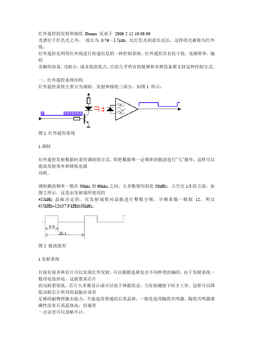
一、红外遥控系统结构红外遥控系统主要分为调制、发射和接收三部分,如图1 所示:图1 红外遥控系统1.调制红外遥控发射数据时采用调制的方式,即把数据和一定频率的载波进行“与”操作,这样可以提高发射效率和降低电源功耗。
调制载波频率一般在30khz到60khz之间,大多数使用的是38kHz,占空比1/3的方波,如图2所示,这是由发射端所使用的455kHz晶振决定的。
在发射端要对晶振进行整数分频,分频系数一般取12,所以455kHz÷12≈37.9 kHz≈38kHz。
图2 载波波形1.发射系统目前有很多种芯片可以实现红外发射,可以根据选择发出不同种类的编码。
由于发射系统一般用电池供电,这就要求芯片的功耗要很低,芯片大多都设计成可以处于休眠状态,当有按键按下时才工作,这样可以降低功耗芯片所用的晶振应该有足够的耐物理撞击能力,不能选用普通的石英晶体,一般是选用陶瓷共鸣器,陶瓷共鸣器准确性没有石英晶体高,但通常一点误差可以忽略不计。
红外线通过红外发光二极管(LED)发射出去,红外发光二极管内部材料和普通发光二极管不同,在其两端施加一定电压时,它发出的是红外线而不是可见光。
图3a 简单驱动电路图3b 射击输出驱动电路如图3a和图3b是LED的驱动电路,图3a是最简单电路,选用元件时要注意三极管的开关速度要快,还要考虑到LED的正向电流和反向漏电流,一般流过LED的最大正向电流为100mA,电流越大,其发射的波形强度越大。
图3a电路有一点缺陷,当电池电压下降时,流过LED的电流会降低,发射波形强度降低,遥控距离就会变小。
红外线接收头的产品知识

4.接收距离:这个一般都是生产厂家依自已的测试来进行标识的 , 无实际对比意义,最主要还是看客户自已机台上测试效果。
5.温度: 工作温度为-20~85℃ 贮存温度为-40~125℃ 焊接温度为最高260 ℃,焊接时间5S。 6.电源电流,最大为3mA。 7.脉宽:500 ~700μs。
• 灌胶型设备投资小,现在国内厂所作的大多是灌胶型产品, 优点是价格便宜,缺点是抗光干扰能力差,接收角度要小 (270度接收),灌胶型同样也分为分塑封和铁壳两种,在选 择接收头时具体要不要带铁壳这要根据设计来定,一般情况 下用在玩具类的产品上使用塑封的,用在家电类产品上用带 铁壳的较多。
• 目前市场上接收头多种多样,从生产工艺上讲,接收头主要是 由以下几种原料构成:接收管芯片(简称PD)、IC(集成电 路)、支架(L/F引脚框)、色素、环氧树脂(胶水)
档次 低端
中低端 中端
高端
厂家 SILICOM SILICOM 欧美亚 士兰微 ADTECH SILICOM
ND ATMEL ATMEL
ND ATMEL ATMEL
NEC ND
型号 2004单
2008 L2004 4766G 2500B 2004多频 ND5300 A2525R338 A2526R338 ND5200 T2525N338 T2526N338 NEC2807 ND5100Leabharlann 支架代码 支架型号A
长支架 (33mm)
B 中支架
C 窄脚内屏
D
2.0支架 (44mm)
E
2.0支架内 屏
型号 接线
A(2004单)
B(2500B)
C(2008)
红外线接收头应用说明书LF0038
1
型号:LF0038(深圳兰丰科技产红外线接收头、发射管、发光二极管等光电系列产品)
1.特性 ●小型设计; ●内置专用 IC; ●宽角度及长距离接收; ●抗干挠能力强; ●能抵挡环境干挠光线; ●低电压工作;
2.应用: ■视听器材(音箱,电视,录影机,碟机) ■家庭电器(冷气机,电风扇,电灯) ■其它红外线遥控产品;
Ice L
θ1/2 f0
fBW VOL VOH TPWL TPWH
2.7
5.5
0.6
0.8
-
无信号输入时
0.1
0.5
※
15
18
+/-45
38
-3Db Bandwidth
-
8
-
Vin=0V Vcc=5V
0.4
Vcc=5V
Vcc-0.3
Vcc
Vin=50mVpVp-p
Min 2.7
-20
规格 -0.3—6.5 -20— +85 -40 —— +125 260(5S)
Typ
Mnx
-----
5.5
38
25
80
单位 V ℃ ℃ ℃
单位 V kHz ℃
12.使用注意: 1).在无任何外加压力及影响品质的环境下储存及使用; 2).在无污染气体或海风(含盐分)的环境下储存及使用; 3).在低湿度环境下储存及使用; 4).在规定的条件下焊接引线管脚,焊接后,请勿施加外力; 5).请勿清洗本产品,使用前,请先用静电带将作业员及电烙铁连接落地线; 6).请注意保护红外线接收器的接收面,沾污或磨损后会影响接收效果,同时不要触碰表面。
4
型号:LF0038
Typical Electrical Curves at Temp=25℃
亿光红外线接收头IRM-H638T-TR2
Technical Data SheetInfrared Remote-control Receiver ModuleIRM-H6XXT/TR2 Features‧High shielding against electric field disturbance.‧Circular lens to improve the receive characteristic.‧Line-up for various center carrier frequencies.‧Low voltage and low power consumption.‧High immunity against ambient light.‧Photodiode with integrated circuit.‧TTL and CMOS compatibility.‧Top-received SMD.‧Suitable burst length ≧10 pulses/burst.‧This product itself will remain within RoHS compliant version.‧Pb free.‧External dimensions 5(L)*7(W)*4(H)mm.DescriptionsThe device is a miniature SMD type infrared remotecontrol system receiver that has been developed anddesigned by utilizing the most updated IC technology. ThePIN diode and preamplifier are assembled on lead frame,the epoxy package is designed as an IR filter. Thedemodulated output signal can directly be decoded by amicroprocessor.Applications1. Light detecting portion of remote control․AV instruments such as Audio, TV, VCR, CD, MD, etc.․Home appliances such as Air-conditioner, Fan , etc.․The other equipments with wireless remote control.․CATV set top boxes․Multi-media EquipmentDevice Selection GuidePART MATERIAL COLORChip Silicon ---Package Epoxy BlackIRM-H6XXT/TR2 Absolute Maximum Ratings (Ta=25℃)Parameter Symbol Rating Unit NoticeSupply Voltage Vcc 0~6 V Operating Temperature Topr -25 ~ +85 ℃Storage Temperature Tstg -40 ~ +85 ℃Recommended Operating ConditionSupply Voltage Rating: Vcc 2.7V to 5.5VElectro-Optical Characteristics (Ta=25℃, and Vcc=3.0V)Parameter SymbolMIN.TYP.MAX.UnitCondition Supply Current Icc --- --- 1.2 mA No signal input Peak Wavelength λp--- 940 --- nmL08 --- ---Reception DistanceL45 5 --- ---mHalf Angle(Horizontal) Θh--- 45 --- deg At the ray axis*1Half Angle(Vertical) Θv--- 45 --- degHigh Level Pulse Width T H400 --- 800 μs Low Level Pulse Width T L400 --- 800 μs At the ray axis*2High Level Output Voltage V H 2.7 --- --- V Low Level Output Voltage V L--- 0.2 0.5 V Notes:*1:The ray receiving surface at a vertex and relation to the ray axis in the range of θ= 0° and θ=45°.*2:A range from 30cm to the arrival distance. Average value of 50 pulses.IRM-H6XXT/TR2 The Notice of Application:Transmission remote control signal consist of four parts: Encode Part, IR Transmitter Source, IRM device, Decode Part1. When IRM-H6XXT code select frequency, it need to well understand the center system ofencode part.2. Strong or weak light of IR Transmitter can affect distance of transmission.3. Minimum Burst Length T burst (number of pulses per burst) : 10 cycles4. It needs to ensure the translation range of decode part if it is applied to the pulse-width range. If the above items hardly assure of its application, it’ll cause NG(no good) message from the edge of signal.Note: This model might not work well with RCA code.Test Method:The specified electro-optical characteristics is satisfied under the followingConditions at the controllable distance.c Measurement placeA place that is nothing of extreme light reflected in the room.d External lightProject the light of ordinary white fluorescent lamps which are not highFrequency lamps and must be less then 10 Lux at the module surface.(Ee≦10Lux)e Standard transmitterIRM-H6XXT/TR2Application Circuit:RC Filter should be connected closely between Vcc pin and GND pin.IRM-H6XXT/TR2Fig.-8 Fig.-9 Relative Transmission Distance vs.Fig.-9 Arrival Distance vs. Ambient TemperatureCenter Carrier FrequencyReliability Test Item And ConditionThe reliability of products shall be satisfied with items listed below.Confidence level:90%LTPD:10%Reflow Terms: JEDEC Level 4 SpecificationDrying; Temp.:125℃ 24hrs Æ Moisture 30℃/ 60% RH 96hrs Æ Reflow Temp.: 260℃±5℃10sec, 3 timesNote:1. Not sooner than 15 minutes and not longer than 4 hours after removal from thetemperature/humidity chamber.2. The time between reflow shall be 5 minutes minimum and 60 minutes maximum.Recommended method of storageDry box storage is recommended as soon as the aluminum bag has been opened prevent moisture absorption. The following conditions should be observed, if dry boxes are not available:z Storage temperature 10℃ to 30℃z Storage humidity ≦60%RH max.After more than 72 hours under these conditions moisture content will be too high for Reflow soldering:In case of moisture absorption, the devices will recover to former condition by drying under the following condition:192 hours at 40℃+5℃/-0℃and 5%RH (dry air / nitrogen) or96 hours at 60℃+5℃and < 5%RH for all device containers or24 hours at 125℃+5℃not suitable for reel or tubes.ESD PrecautionProper storage and handing procedures should be followed to prevent ESD damage tothe devices especially when they are removed from the Anti-static bag. Electro-Static Sensitive Devices warning labels are on the packing.Recommended Solder Profile(1) Reflow soldering should not be done more than two times.(2) When soldering, do not put stress on the IRM-H6XXT/TR2 Series devices during heating.(3) After soldering, do not warp the circuit board.Soldering IronEach terminal is to go to the tip of soldering iron temperature less than 350℃ for 3 seconds within once in less than the soldering iron capacity 25W. Leave two seconds and more intervals, and do soldering of each terminal. Be careful because the damage of the product is often started at the time of the hand solder.RepairingRepair should not be done after the Devices have been soldered. When repairing is unavoidable, a double-head soldering iron should be used (as below figure). It should be confirmedBar Code Label亿光一级代理商超毅电子EVERLIGHT ELECTRONICS CO.,LTD.IRM-H6XXT/TR2Label Form SpecificationCPN: Customer’s Production Number P/N : Production Number QTY: Packing Quantity CAT: None HUE: None REF: Reference LOT No: Lot Number MADE IN CHINA: Production PlacePbRoHSIRM-H6XXT/TR2Notes1. Above specification may be changed without notice. EVERLIGHT will reserve authority on material change for above specification. 2. When using this product, please observe the absolute maximum ratings and the instructions for using outlined in these specification sheets. EVERLIGHT assumes no responsibility for any damage resulting from use of the product which does not comply with the absolute maximum ratings and the instructions included in these specification sheets. 3. These specification sheets include materials protected under copyright of EVERLIGHT corporation. Please don’t reproduce or cause anyone to reproduce them without EVERLIGHT’s consent.EVERLIGHT ELECTRONICS CO., LTD. Office: No 25, Lane 76, Sec 3, Chung Yang Rd, Tucheng, Taipei 236, Taiwan, R.O.CTel: 886-2-2267-2000, 2267-9936 Fax: 886-2267-6244, 2267-6189, 2267-6306 http:\\Everlight Electronics Co., Ltd. Device No:DMO-0000008http:\\ Prepared date:09 -26-2007Rev1Page: 11 of9Prepared by:IBU_NPID2。
红外接收头入门宝典
红外接收头入门宝典提要:这份资料里包含红外接收头所有基础资料,从最基本的红外是什么讲到红外接收头的应用,如果让老师在课堂上讲,真是讲到口水都干。
因此这是一份古今中外入门宝典,是菜鸟居家旅行的必备良药。
红外:在弄懂红外接收头之前,我们先了解一下什么是“红外”。
红外其实是红外线的简称(中国人的传统美德就是节俭,所以能省一个字就省一个),是一种光谱(电磁波)里在0.75至1000微米之间你我都看不到的光线。
只是说的话你可能不太明白,没图没真相,还是看图最直接,请看下图:现在你应该有点概念了吧,红外线就一种我们看不见的光而已。
所以嘛,眼见不一定为实,眼不见也不一定为虚。
名称:继续讲正题,从上面的了解,我们可以推出,红外接收头就是一种用来接收红外线的东西。
这个东西有很多种称呼,一般叫红外接收头,简称接收头,还可以叫红外接收器,红外接收管,红外接收模块,遥控接收头,也可以复杂一点,就是在红外后加个线字,如红外线接收头,然后就可以举一反三,再接再厉了。
除了中文名字,红外接收头还有英文名字,叫Infrared Receiver Module,简称IRM,与国际接轨。
外观:接着,我们来看看红外接收头长什么样子,其实还蛮帅的,而且各具个性。
虽然样子很个性,但是按外观还是可以分两类的:鼻梁型,圆球型(圆点型)。
而鼻梁型里可以细分为大鼻梁,标准鼻梁,小鼻梁。
除此之外还有其他特殊的,如超薄型,迷你型,草帽型,贴片型,带线接收头。
分类:除了从外观上分类之外,还可以按封装方式分类,这样比较准确。
目前市场上能买到的接收头从封装方式上分主要有两大类:压模型和灌胶型。
一般来说,鼻梁型属于灌胶型,圆球型属于压模型。
从两种封装工艺上来说,压模型设备投资较大,所用胶饼价格较贵,所以整体价格要贵些,当然其抗光干扰能力要强,接收角度要大(圆型360度接收);灌胶型设备投资小,现在国内厂所作的大多是灌胶型产品,优点是价格便宜,缺点是抗光干扰能力差,接收角度要小(270度接收)。
如何辨别红外线接收头出现故障的具体位置
如何辨别红外线接收头出现故障的具体位置文章出处:广州市超毅电子有限公司亿光红外线接收头是属于光电元器件里的红外线接收模块类型的。
有贴片型也有直插型。
而已应用非常广泛。
下面超毅电子为你阐述怎样辨别接收头出现故障的具位置。
亿光红外线接收头虽然采用贴表工艺,修理难度并不是很大,只是因为缺少资料,贴片元件密密麻麻,冷眼一看都一个模式,使一些修理者对贴片电路望而生畏。
贴片电路是今后PCB电路的必然趋势,是对家电维修人员的又一次挑战,我们必须逐步适应。
1、红外接收头由于工作在低电压、小电流的情况下,一般不会出现烧毁电路板的故障,晶体管和集成电路的损坏率也不大。
故障率最高的是接收频率偏移,多是因为进水或电路板受潮使超再升电路停止振荡,业余修理应多做清洗、驱潮工作,多测量电压(波形),尽量少拆卸元件。
2、对于业余修理可以采用整体代换法,现在用的接收头,无论是调感式还是调容式,也无论是分立直插件还是贴表器件或是混合方式(阻容元件用贴片,晶体管、集成电路、电解电容用直插件),它们之间几乎完全可以互换使用,只要找到GND(接地)、+V(电源正)、OUT(信号输出)端的对应关系,并重新调整红外线接收头的接收频率即可。
3、一旦确定红外线接收头电路工作不正常,就可以按以下方法区分故障来自哪一部分电路,即高放级、超再升级还是放大、整形电路。
检查放大、整形电路时,信号的输入椭出点是查找故障的关键点。
具体方法是用红外遥控器发射信号,用示波器观察放大、整形电路有无信号输入(如LM358F的⑤脚),如有信号波形,说明高放电路、超再升电路基本正常,故障在放大、整形电路;如测不到信号,则故障在超再升电路之前。
对放大、整形电路的检修,可以测量LM358的引脚电压,并和正常值对照,如果不正常,多为集成电路本身损坏。
4、对超再升电路的检修,可以先检查晶体管的直流电压,如不正常,检查直流偏置电路或晶体管本身;直流偏置电压正常后,再检查交流反馈电路,对贴片电容最好用代换法。
AO-R123_R123系列OEC红外线遥控器接收头-奥伟斯
AO-R123C6E-SS(T)描述该封装由高速PIN光电二极管和包装中的前置放大器IC组成。
红外遥控系统接收器2.特点◆2.7〜5.5 V供电电压,低功耗◆屏蔽电场干扰◆高抗环境光◆与主板的便捷接口◆TTL和CMOS兼容性◆一包模具◆符合RoHS3. Applications◆电视,VTR,音频,空调,汽车立体声设备,计算机,室内控制设备,和需要远程控制的设备R123M-10H(S)DescriptionThe R123M-10H(S) consist of a PIN Photodiode of high speed and a preamplifier IC in the package as anreceiver for Infrared remote control systems2. Features2.7〜5.5伏电源电压低功耗◆屏蔽电场干扰◆高抗环境光◆与主板的便捷接口◆TTL和CMOS兼容性◆一包模具◆符合RoHSe3. Applications◆电视,VTR,音频,空调,汽车立体声设备,计算机,室内控制设备以及需要远程控制的设备4. Package OutlinesSee the attached Drawing No. RM-R12□□-4PIN-ASY-01描述:AO-R123C6E-SS(S)由高速pin光电二极管和包装中的前置放大器IC组成,作为红外遥控系统的接收器Features◆2.7〜5.5 V供电电压,低功耗◆屏蔽电场干扰◆高抗环境光◆与主板的便捷接口◆TTL和CMOS兼容性◆一包模具◆符合RoHS3. Applications电视,VTR,音频,空调,汽车立体声设备,计算机,室内控制设备,和需要远程控制的设备4.Package OutlinesSee the attached Drawing No. RM-R12□□-4PIN-ASY-011. DescriptionThe R123M-10H(S) consist of a PIN Photodiode of high speed and a preamplifier IC in the package as an receiver for Infrared remote control systems2. Features2.7〜5.5伏电源电压低功耗◆屏蔽电场干扰◆高抗环境光◆与主板的便捷接口◆TTL和CMOS兼容性◆一包模具◆符合RoHSe3. Applications◆电视,VTR,音频,空调,汽车立体声设备,计算机,室内控制设备以及需要远程控制的设备4. Package OutlinesSee the attached Drawing No. RM-R12□□-4PIN-ASY-015.Absolute Maximum Ratings [Ta = 25℃ ] Reliability Test注意:* 1。
- 1、下载文档前请自行甄别文档内容的完整性,平台不提供额外的编辑、内容补充、找答案等附加服务。
- 2、"仅部分预览"的文档,不可在线预览部分如存在完整性等问题,可反馈申请退款(可完整预览的文档不适用该条件!)。
- 3、如文档侵犯您的权益,请联系客服反馈,我们会尽快为您处理(人工客服工作时间:9:00-18:30)。
3. Features
1) Transfer Mold Package. 2) Wide Operating Supply voltage 2.7V ~ 5.5V 3) Supply Current : 3.0V(0.4mA), 5.0V(0.42mA) 4) Band pass filter center frequency : 20 ~ 60Khz 5) Epoxy IR filter characteristic : 810n~940nmm 6) Maximum interference safety against optical and electrical disturbance. 7) Internal filter for a high frequency lighting fluorescent lamp. 8) Internal Pull-Up output. 9) Operation with short burst possible. 10) Lead(Pb)-free component.
. Vcc
2.7
-
5.5
V
N/Signal (3.0V) 0.3 0.4 0.5
㎃
Icc
N/Signal (5.0V 0.35 0.42 0.6
㎃
Peak Wavelength (※1)
λp
-
940
-
㎚
B.P.F Center Frequency
fo
36
-
60
㎑
High Level Output Voltage (※1)
Future Technology of Optical Sensor
Miniature Infrared Remote Control Receiver
.
OS-OPTO TECHNOLOGY CO;LTD ADD:Bridge Wing Building 1008,Qiaotao,Fu Yong Town,Bao'an District, Shenzhen,Guangdogn,China TEL:755-27361616 MB:13556894958 FAX;755-33119977 Http:// Email:adam@
▶ Minimum Burst Length (tburst ) : 12pulses ▶ Minimum Gap Time Between the burst
(tburst gap) : 16pulses
Data word
tdata
tpause
Data word
▶ Minimum Gap Time between the data commands (tpause) : 23㎳
4. Absolute Maximum Ratings
.
1) Supply Voltage : 6.0V
2) Supply Current : 2.0mA
3) Operating Temperature : -20℃ ~ +85℃
4) Storage Temperature : -30℃ ~ +90℃
Ta=+121℃ 100%RH, P=1atm, t=4hr
. Ta=+350±5℃, 3s
Consumption current ICC < 1.0mA D (Vcc=5.0V)
C=0 / n=22 C=0 / n=11
satisfies the standard (fig.2, fig3) under the conditions below against the standard transmitter.
ON/OFF pulse width is to be satisfied within 0.3m~ arrival distance length.
4) Carrier Frequency
Type
OS-○○ 32○○ OS-○○ 36○○ OS-○○38○○ OS-○○40○○ OS-○○ 56○○
Carrier Frequency
32.7 ㎑ 36.0 ㎑ 37.9 ㎑ 40.0 ㎑ 56.7 ㎑
3
SHENZHEN OS-OPTO TECHNOLOGY CO;LTD
Ta=-20℃, Vcc=5.0V t=500hr
High level output voltage C=0 / n=22
VOH > 4.5V
High Temp./ High Hum. 5
Bias (※1,※2)
Ta=+85℃, 85%RH VCC=5.0V, t=500hr
VOL (Vcc=5.0V) C=0 / n=22
Low level output voltage
Temperature Cycle 6
(※2, ※3)
Ta=-20℃(0.5h) to +85℃(0.5h) 20cycle
VOL < 0.4V ICC (Vcc=5.0V)
C=0 / n=22
7 P.C.T (※2) 8 Solder Heat (※2)
① Confidence level : 90% ② LTPD : 10% / 20%
No.
Test Item
Test Conditions
Judgment Standard
Fail(c) / Samples(n)
1 High Temp. Storage (※2) Ta=+90℃, t=500hr
C=0 / n=22
GND
2
SHENZHEN OS-OPTO TECHNOLOGY CO;LTD
OS - Series
6. Electro-Optical Characteristics
1) Absolute Maximum Ratings
Parameter
Symbol
Supply Voltage
(at 25℃ Unless otherwise note)
Ratings
Unit
6.0
V
2.0
㎃
-20 ~ +85
℃
-30 ~ +90
℃
260, t<10sec
℃
2) Recommended Operating Conditions
Parameter
Operating Voltage Input Frequency
tWH
Period = 1.2㎳
400
-
800 ㎲
Internal Pull_up Resistance
Rout
94
㏀
Arrival Distance (※1)
±0˚
-
13
-
m
D
±30˚
-
11
-
m
Output Form
Active Low Output
※1. Distance between emitter and detector specifies maximum distance that output wave form
Rev3.0 (100101)
OS - Series
1. Application This Specification is applied to inspection and approval of the IR Receiver Module for Infrared Remote Control Application.
2. Description
The OS-Series are miniaturized r eceiver for infrared remote control system. The Pin Photodiode and preamplifier are assembled on lead frame. The epoxy package is designed as IR filter. The module has excellent performance even in disturbed ambient light application and provides protection against uncontrolled output pulses.
Symbol
Vcc fin
Ratings
2.7 ~ 5.5 20 ~ 60
Unit
V ㎑
3) Electro-Optical Characteristics
(Ta=25℃)
Parameter
Supply Voltage
Supply Current
Symbol Conditions Min Typ Max Unit
0˚
20˚
40˚
100
60˚
V
90
H
80˚
80 60 40 20 0 Relative Sensitivity(%)
4
SHENZHEN OS-OPTO TECHNOLOGY CO;LTD
OS - Series
7. Reliability Test Item and Standard. 1) All output products shall satisfy below Reliability test items. 2) Related sampling quantity and acceptance/failure judgment standard accordance with MIL standard MIL-STD-883 is as listed below.
5. Functional Block Diagram