UV电子电源说明书
UVR6说明书
U.V.R.62)U.V.R.6ELECTRONIC REGULATOR2.1)General characteristcsThe UVR6 type voltage regulator is an advanced design electronic regulator that ensures excellent and during starting . The regulator is equipped with a complete protection system against operation conditions that could be dangerous for the machine .The UVR6 regulator is suitable for power outputs above or equal to 85KV A ,both three-phase and single phase.The terminal board is equipped with indications to help connection and avoid errors.Some connection diagrams that are suitable for different confgurations are given on the back of the regulator (see fig.9)2.2)Technical characteristics2.2.1)SupplyThe supply to the regulator can be from 170 to 270 Vac between terminals + and 2 of the terminal board , with +and B not connected, or from 80 to 160 Vac between terminals +and 2 but with +and B connected to each other . Supply can also be separate from the sensing and in this case should be insulated from it.2.2.2)sensingThe regulator is equipped with three differential sensing inputs (terminals1-2,3-4,5-6),which measure up to three different machine voltages.In this way you can check the average voltage on one or three phases of your choice .The most common connections are the following:a)Direct voltage adjustment of one of the phase windings ,with the machine either star or delta connected.b)Direct adjustment of the voltage of the three phase windings (also for12 terminal machines ),with the machine either star or delta connected.In both cases(“a”and “b”),the passage of the machine connection from triangle to star does not need regulator connection modification.c)Direct adjustment of the voltage to the terminals being used ,with machine erIther star or delta connected.2.3)Adjustments2.3.1)V oltage precisionThe voltage remains within +_1% of the pre-set value when passing from zero to full load ,from cosφ1to 0.8 and with turn variations of up to-6% of the nominal value. The precision of the voltage improves if the regulator sensing inputs are connected directly to the terminals being used (see point c of the previous para-graph).2.3.2)V oltage adjustmentThe voltage can be adjusted wsing the potentio-meter marked “VOLT”. It is also possible to regulate the voltage at a distance of +_5% byinserting a 100 KOhm potentiometr onto the relevant terminals of the terminal board that are markerd a variable resistance symbol.2.3.3)Transitory reply time adjustmentThe regulator is equipped with a “STAB”stability potentiometer with which it is possible to vary the regula-for reply in a way that limits the swing and obtains from the machiine a minimum voltage reset time at nominal value ,after the application or release of a load .This permits optimum use of the UVR6regulator for the whole range of Mecdc Alte alternators.2.4)ProtectionsThe UVR6 regulator is equipped with two protection systems,and when they intervene the following LEDs light up:a)Delayed protection for overloads(yellow LED).b)Low speed protection (red LED)Both protections have an intervention threshold that can be adjusted using the respective potentiometers. The protections cause an putput voltage decrease reducing overheating of the machine ,so reducing overheating of the exciter rotor .The overload protection has a delay that let’s the machine overload briefly ,for electric motor starting or other needs.The regulator also has a third LED (green) which when lit indicates that the regulator is working correctly .All these signals can be observedremotely using the S.P.D.96/A type “REMOTE PROTECTION SIGNALLER”that is available upon request (see paragraph 3).FuseThe UVR6 electronic regu lator is equipped with a fuse .which protects the alternator from overheating in cases of regulator malfunction .The fuse can be replaced easily .but the new one must have the same characteristics as the one being replaced (250v-6.3A,quick acting,F type).2.5Usage fieldThe UVR6 can be used with all voltages from 80 to 480v Vac at 50HZ . It can also function at 60HZ by bridging the “60HZ”terminals of the regulator terminal board.The admissible calibration field corresponds to the one specified for Mecc Alte alternators.2.6)Self-excitationThe regulator is equipped with a “starter”device that utilises the residual voltage of the machine for supply and excitation adjustment.This permits safe alternator excitation ,also with very low residual voltages and in very short time ,avoiding voltage swings during the starting phase .In this way ,the voltage rises to the stavilised nominal value ,approximately at the same moment when the speed reaches nominal value ,even with prime movers with very fast starting ramps. 2.7)TEST PROCEDURES2.7.1)Workbench test procedure-)Prepare the connection diagram as shown in figure 10.-)Before supplying the cercuit with current ,take the “VOLT”and “STAB”trimmers to minimum (turn anticlokwise),and the “AMP”and “HZ” trimmers to maximum (turn clockwise ).The variac cursor should remain at minimum .-)Switch on the variac and increase the voltage slowly ,making sure that the light switches on and then immediately off.-)Raise the variac voltage to approximately 200 Vac :the light should not light up.-)Turn the “VOLT”trimmer slowly clockwise .The lamp should switch on ,starting from minimum and going to maximum brightness.Make sure that the green LED switches on then immediately off again during the brightness intensity changen .-)Take the “VOLT” trimmer to maximum .The light switches on fully and the green LED remains unlit .Turn the “AMP”trimmer to minmum (anticlockwise)and wait approximately 20 seconds in these conditions .You should see that the overload protection switches off the lamp and lights the yellow LED .Almost immediately after ,the green LED switches on ,as does the light but only slightly .-)Slowly turn the “AMP” trimmer towards maximum .Make sure that the light illuminates with increasing intensity .Leave the “AMP”trimmer at half range .-)In these conditions ,the light should flicker if the “STAB”trimmer is turned slowly clockwise .When the “STAB”trimmer reaches maximum ,the flicker turns into intermittent light.-)Take the “STAB”trimmer back to minmum .the green and yellow LEDs should be lit ,and the light should be at medium brightness .-)Turn the “HZ”trimmer to minmum (anticlockwise).Make sure that the red LED switches on .NOTE: if the test bench is at 50HZ and the red LED does not illuminate ,bridge the “HZ”terminals of the terminal board .if the test bench is at 60 HZ and the red LED does not light up ,this does not mean that the regulator has problems .The low frequency protection should ,instead ,be tested in the machine .-)Short-circuit the remote potentiometer terminals .The light should switch on with greater intensity .If during all the above tests the described behaviour happens ,the regulator being examined is suitable for operation .2.7.2)Machine test procedureThe regulator should be connected as shown in the relevant diagram in figure 11.-)Before starting the system ,turn the “VOLT”and “STAB”trimmers fully anticlockwise and the “AMP”and “HZ”trimmers fully clockwise.-)Connect a light between the generator phase and neutral (select the working voltage of the light in relation to the nominal value of the generator phase-neutral voltage).-)V oltage calibrationThe output voltage may oscillate when the generator is at no load ,at nominal speed and with the “VOLT”voltage trimmer clockwise.The generator voltage should rise and stabilise itself .Increase the voltage to the nominal value .in this situation only the green LED should be lit. -)Stability calibrationTo adjust regulator stability ,slowly turn the “STAB”trimmer clockwise until the light that was previously connected between phase and neutral begins flashing slightly .Turn the “STAB’ trimmer anticlockwise until the light becomes perfectly staable .-)Overload protection calibrationTo adjust the “AMP”overload protection apply a norminal load to the alternator then decrease the speed by 10% and turn the “AMP” trimmer fully anticlockwise .After a pause of 15-20 seconds ,the generator voltage value should decrease and the yellow LED should light up ,in these conditions ,slowly turn the “AMP’trimmer clockwise until the output voltage value is at 97% of the nominal value -the yellow LED is still lit .when returning to normal speed ,the generator voltage return to nominal value .if this does not happen ,repeat the calibration.-)Low speed protection calibrtionIf the machine is to work at 60HZ make sure that the “60HZ” terminals of the electronic regulator are bridged .To adjust the low frequency protection ,make the gene-one .slowly turn the “HZ”trimmer in an anticlockwise and at the same time make sure that the red LED lights up .when the speed is increased ,the generator voltage should normalise and the red LED should swich off ,Take the speed back to the nominal value.If during all the above tests the described behaviour happens ,the regulator being esamined is suitable for operation.2.8)Replacement of electronic regulators that are no longer produced UVR6 could replace old regulators (RT80,RT80A,RT83,RT83N)U.V.R.6U.V.R.6ELECTRONIC稳压器2.1)characteristcs一般UVR6式电压调节器是一种先进的设计,电子调节器,以确保优良,在起动过程中。
uv电子电源接线方式
一、Uv电子电源操作说明:
A、前面板接线端口说明
3芯插孔或品字座:
电源输入:L1、L2、L3为交流电输入;第四个插孔为地线
4芯插孔:
UV输出:从左往右:U、V
(1)正常输出:灯管接U、V
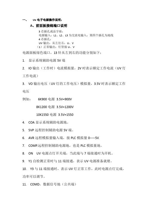
电源面板绿色端口,13针从左到右的功能分别如下:
1. 显示系统辅助电源5V端
2. IO输出(工作时)电流模拟量,2V时表示额定工作电流(UV灯工作电流)
3. VO输出电压(UV灯的工作电压)模拟量,3.5V时表示额定工作电压
例如:6K900电源3.5V=900V
8K1200电源3.5V=1200V
10K1550电源3.5V=1550
4. COA显示系统辅助电源地。
5. 5VP远程控制辅助电源5V端。
6. AVR远程模拟量输入端,接PLC模拟量0-----5V.
7. COMP.远程控制辅助电源地,也是PLC模拟量地。
8. ON UV电源点灯开关端,当此端与7端接通时为开机。
9. Y1自检测正常时与11端接通,表示UV电源准备就绪。
10. Y3与11端接通时,表示UV灯正常工作,此时电源点灯完成,功率可以调节。
11. COMD,数据信号地(公共端)
12. Y8灯管管压不足时报警端,开关量。
13. Y4灯管管压过高时报警,当Y4和Y8同时亮时,表示电源异常。
分别有:UV电源内部超温,电源输入缺相,电网电压过低或过高等等。
uv操作说明书

UV光解设备操作说明书一、原理1、本产品利用特制的高能高臭氧UV紫外线光束照射恶臭气体,裂解恶臭气体如:氨、三甲胺、硫化氢、甲硫氢、甲硫醇、甲硫醚、二甲二硫、二硫化碳和苯乙烯,硫化物H2S、VOC类,苯、甲苯、二甲苯的分子键,使呈游离状态的污染物分子与臭氧氧化结合成小分子无害或低害的化合物,如CO2、H2O等。
2、利用高能高臭氧UV紫外线光束分解空气中的氧分子产生游离氧,即活性氧,因游离氧所携正负电子不平衡所以需与氧分子结合,进而产生臭氧。
UV+O2→O-+O*(活性氧)O+O2→O3(臭氧),众所周知臭氧对有机物具有极强的氧化作用,对恶臭气体及其它刺激性异味有极强的清除效果。
3、恶臭气体利用排风设备输入到本净化设备后,净化设备运用高能UV紫外线光束及臭氧对恶臭气体进行协同分解氧化反应,使恶臭气体物质其降解转化成低分子化合物、水和二氧化碳,再通过排风管道排出室外。
4、利用高能UV光束裂解恶臭气体中细菌的分子键,破坏细菌的核酸(DNA),再通过臭氧进行氧化反应,彻底达到脱臭及杀灭细菌的目的。
二、产品性能特点有机废气气体利用排风设备输入到本净化设备后,净化设备运用高能UV紫外线光束及臭氧对有机废气进行协同分解氧化反应,使恶臭气体物质其降解转化成低分子化合物、水和二氧化碳,再通过排风管道排出室外。
UV高效光解废气净化设备的性能优势1、能高效去除挥发性有机物(VOC)、无机物、硫化氢、氨气、硫醇类、芳香类(含苯环)等主要污染物。
2、无需添加任何物质:只需要设置相应的排风管道和排风动力,使工业废气通过本设备进行分解净化,无需添加任何物质参与化学反应。
3、适应性强:UV高效光解废气净化设备可适应高浓度,大气量,不同工业废气物质的净化处理,可每天24小时连续工作,运行稳定可靠。
4、运行成本低:UV高效光解废气净化设备无任何机械动作,无噪音,无需专人管理和日常维护,只需作定期检查,本设备能耗低,设备风阻极低<50pa,可节约大量排风动力能耗。
大功率智能UV灯电子电源

2011[E-STAR]电子电源使用手册工业用UV灯电子电源安装使用说明工业用UV灯电源解决方案-------节约能源、提高生产效率、降低生产成本苏州益仕达电源科技有限公司目录1.符合性信息 ----------------------------------------------------------12.关于本设备-----------------------------------------------------------23.标志说明-------------------------------------------------------------24.安全预防措施---------------------------------------------------------25.产品附件及确认-------------------------------------------------------36.产品机械安装---------------------------------------------------------37.冷却系统-------------------------------------------------------------68.电器连接8.1主电源连接------------------------------------------------------------------------------------------68.2 辅助电源连接--------------------------------------------------------------------------------------78.3 外部控制连接--------------------------------------------------------------------------------------78.4 UV 灯管连接---------------------------------------------------------------------------------------128.5 产品散热风扇连接-------------------------------------------------------------------------------128.6 24V输出信号说明--------------------------------------------------------------------------------12 9.产品功能介绍9.1 启动电灯--------------------------------------------------------------------------------------------129.2 停止工作关闭电源-------------------------------------------------------------------------------129.3 产品功率设置-------------------------------------------------------------------------------------129.4 自动热灯--------------------------------------------------------------------------------------------149.5 长待机------------------------------------------------------------------------------------------------169.6 热灯电灯---------------------------------------------------------------------------------------------16 10.机械尺寸-------------------------------------------------------------------------------------------------16 11.滤波器----------------------------------------------------------------------------------------------------17 12.电气接线图----------------------------------------------------------------------------------------------18 13.规格参数--------------------------------------------------------------------------------------------------19 14.故障维修--------------------------------------------------------------------------------------------------20 15.质量保证--------------------------------------------------------------------------------------------------20本产品必须按照产品的相关国际和国内标准进行连接和安装。
UV光源操作说明书(1)

UVEC-4操作说明书注意事项1.照射过程中,不能用照射头对准人体的皮肤,眼睛等身体部位。
2.将照射头工作位置固定,使用照射按钮或脚踏开关,控制照射头工作。
3.不允许拧动照射头前端透镜,否则会影响到输出的紫外线能量。
4.请用干纸巾擦洗设备。
5.确保设备干燥的工作环境。
6.设备处于工作状态时,请不要设置参数。
7.设备断电或通电不久时,请不要触摸照射头。
设备安装1.设备安装图解通道1照射头接口固定导线小按钮脚踏开关接线孔通道2照射头接口通道3照射头接口通道4照射头接口电脑信号线接口电源接口电源开关2.脚踏开关连接代码1-4端口分别连接控制通道1-4照射头脚踏开关。
4个端口连接方式相同,我们将为您示范端口1脚踏开关的连接。
端口1左接线孔和右接线孔各有一个用于固定导线的小按钮,按下这个按钮,将脚踏开关的两条导线不分顺序插入孔中,然后松开按钮,连接完毕。
如果需要断开连接,只需按下接线孔的小按钮,拔出导线即可。
3.照射头连接照射头连接端与设备通道借口针孔对应,推进即可。
4.电脑信号线连接将电脑信号线与设备COM接口对应连接。
5.电源连接将电源适配器接头与设备电源接口对应连接即可。
设备操作操作界面图解功能键说明操作键名称功能确定确定设置取消返回上一级菜单菜单进入主菜单,辅助通道设定向上方向键选择设置项,辅助通道设定向下方向键选择设置项,辅助通道设定向左方向键选择设置项,辅助通道设定向右方向键选择设置项,辅助通道设定总照射控制4个通道同时照射或同时停止分立照射按钮1控制通道1照射或停止分立照射按钮2控制通道2照射或停止分立照射按钮3控制通道3照射或停止分立照射按钮4控制通道4照射或停止操作术语注释术语名称注释固定功率照射光功率可在0~100%范围内设定,设定好后光功率恒定照射。
阶梯功率照射系统提供16个阶梯照射,每个阶梯可分别设置照射时间和功率。
人工控制只能用脚踏开关控制照射头即时工作。
自动控制脚踏开关,分立照射按钮和总照射键都可控制照射头工作。
BYHX-UVLW12020产品手册
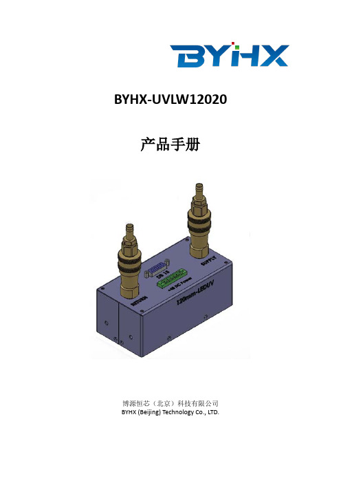
BYHX-UVLW12020 产品手册博源恒芯(北京)科技有限公司BYHX (Beijing) Technology Co., LTD.重要声明●北京博源恒芯公司保留本文件的所有版权!未经北京博源恒芯公司的书面许可,任何人员、机构不得对本手册的全部或部分内容,以任何方式进行复制。
●本手册的内容,会根据相关情况变化予以变更,变更不另行通知。
●北京博源恒芯公司尽力维护此手册内容的正确性,因技术更新缘故导致的文档更新恕不再单独说明。
如果用户在使用中发现手册有描述不当之处,欢迎及时向我们提出。
●此手册的所有技术接口、设置、软件等,均与所对应的整机系统的相关部件配置及参数存在匹配关系。
若这些部件配置或参数发生变化,则本控制系统的软硬件组合及相关设置或随之发生改变。
客户采购本公司的控制系统,并应用于喷绘机的批量生产时,务必确认相关配套部件与本文此处所描述的一致性或兼容性,因不一致或不兼容导致的问题,博源恒芯不承担责任。
Copyright © 2011,2012,2013,2014北京博源恒芯科技有限公司目录一、UV灯参数 (3)二、产品特征 (3)三、光源系统组件 (4)四、控制接口 (4)五、电源规格 (5)六、安装 (6)七、维护与保养 (7)八、UV灯故障指导 (9)九、订货信息 (9)此手册用于博源恒芯(北京)技术有限公司自主研发BYHX-UVLW12020型UV 灯。
UV灯采用金属外壳,使用波长390-395nm的纯UV光源紧密排列;在使用过程中不产生任何气体,保证生产过程的绿化。
一、UV灯参数型号BYHX- UVLW12020外观尺寸(mm) 150(长)x 75(宽)x 60(高)输入电压(V) DC 48 V输入功率(W) 480 W输出功率(W) 384 WUV灯波长(nm) 390-395nm水流量4L/min折射镜规格(mm)119.5(长)x 19.5(宽)重量UV灯功率密度UV LED视角半角40度(正负20度)二、产品特征✧UV灯体积小,安装简便✧UV灯波长390-395nm✧支持功率调节✧UV灯输出功率高达384W✧及时开关:<50ms✧使用寿命长✧使用环保三、光源系统组件下图显示光源系统运作所需零件,注意在没有冷却水的情况下勿运行UV灯。
UV无极调光电源

新研制成功国内首家UV灯和金属灯均可使用的UV无极调光电源电源(UV 灯电源)-UV无级调光电源。
用户安装此设备后可直接进行外接UV灯管,即可形成整套UV光源系统。
适合于自动丝印设备、胶印设备、喷涂设备的UV固化技术改造和加装。
完全替代传统的变压器+电容模式,此项技术以前国内空白,国外才有(如果需要,完全靠进口)。
一、宽电压输入、输出;适用各种灯管。
1、产品自带BUCK稳压电路,能工作在AC340V~440V。
2、当电压过低时机器自动保护。
3、输出电压500V-800V可以设置。
二、节能效果非常好。
1.与传统变压器比较能节能30% ~50%。
2.效率达到98%。
3.有效提高功率因素能达到0.98,有效解决工厂无功功率烦恼。
三、输出能量稳定1、控制系统采用功率矢量控制算法控制,保证输出功率恒定可调。
2、无论电压波动、环境温度波动,输出能量依然恒定。
彻底解放工程师繁琐的工作。
四、使用简单、方便灵活。
1、智能启动,自动检测灯管状态。
2、0-10V电压无极控制能量输出。
3、闲时一键及时待机,能有效节约能源并延长灯管寿命。
一键恢复能量,立即恢复生产(只需1秒钟)。
4、直观的输出电流、电压显示。
五、支持高端系统集成 - - 内置标准MODELBUS协议,为集成系统提供RS485接口。
1、系统控制机器启停。
2、系统监控机器运行状态。
3、系统控制机器输出能量。
1.印刷行业UV油墨快速固化2.木制品行业UV漆快速固化3.橡塑制品行业表面UV涂层快速固化4.金属制品行业表面UV涂层快速固化5.电子产品行业表面UV涂层快速固化6.各类涂漆生产线表面UV涂层快速固化。
最新UV灯无极调光电源

<ioo00eoooiwuo 9iW40 now无极UV 电源系统采用变频技术的高速开关,在很短的时间转换灯管电流。
灯管发射的光非常稳定,这种稳定的输岀使得无级txcfl A sivc A artcp调光UV 系统能够比传统变压器+电容系统,输岀更高的光强。
更高的强度导致更快的固化,同时较少灯管电极热量,延长灯管寿命.cntensjlyqwckd ・rxitwerbeaisitielampo-?w--UVPoMr A r-Plirssfjbleintensi ty0tw-oo«- QQCO'!图一:输入电压与光强关系 图二:典型点灯过程3.输出波形平稳Tron A ornimbal A 5l f-ucLLatn§(4)加测intensityVariationvsLineVoltageOJOC-t 0300 02^0-I020041ji 0150-[ 0300-\ OOflO-图三:强度输出波形比较4.特有的待机模式-能耗降低,温升最小,寿命延长uv 电源电流控制能力允许调整灯管电流。
操作员可以为特定的胶水特性或是满足基材温度要求,改变灯管强度。
UV 电源系统还拥有待机模式,以在不做固化情况下,减少系统温度和额外的光辐射。
这种模式节省电力消耗,减少固化区域温度升高,增加系统寿命。
UV 电源系统还可以将待机模式和内置快门结合起来。
在快门关闭过程种,灯管热量全部释放到反射罩内部,为了保持稳定的灯管温度,防止过热,强度最低可以减少到10%在这种休眠状态,能量消耗降低,环境温升最小化。
因为灯管温度保持恒定,系统能够很快恢复到预定的工作强度,提供需要的固化。
图四:柱快门周期,u\/灯管强度快速恢复5. 体积小'重量轻V2000电源出色的稳定设计,使得UV 固化系统是业内最小和最轻的。
传统UV 变压器+电容系统一般重50kg 以上,韦特UV 相应电源只有10kg 左右。
- 1、下载文档前请自行甄别文档内容的完整性,平台不提供额外的编辑、内容补充、找答案等附加服务。
- 2、"仅部分预览"的文档,不可在线预览部分如存在完整性等问题,可反馈申请退款(可完整预览的文档不适用该条件!)。
- 3、如文档侵犯您的权益,请联系客服反馈,我们会尽快为您处理(人工客服工作时间:9:00-18:30)。
UV电子电源说明书
该UV灯电子电源可以用于各种UV设备机器上,如UV涂装设备,UV生产自动线,UV固化设备,UV印刷设备,红外线隧道炉等UV机械。
这是一款完全可以替代UV变压器与UV电容组合的一款高性能UV光源系统。
既可以为UV汞灯供电,也可以为UV卤素灯、UV镓灯供电,免串接电容,直接与UV灯管、UV灯罩连接使用。
UV电子电源可以对UV灯管作出10%~100%的无级调控,可满足各种UV固化工艺需求。
UV电子电源调光动态响应速度快,从待机到全功率输出时间只要8毫秒,无任何系统震荡;可以与PLC连接进入人工界面操作,可作出10%的长时间待机,彻底避免系统稳定时间长,安全性能低等弊端,同时彻底改变了依靠电容来调节灯光的强弱控制方式,且电容的耐压强度远远不够。
PLC安装接线简单,操作方便,无须密封安装在箱体内,可安装在通风良好的地方,大幅度节省安装、运输成本。
技术特性
1、高频方波技术(18KHZ方波输出),比传统UV变压器增加20%以上的UV能量输出,能够以闪光灯模式工作,降低能耗;
2、软开关启动系统,大幅度减低启动时间(约45秒),延长灯管使用寿命;
3、单片机动态控制技术,使电源转换效率达到更高,自动找到灯管的工作电压和电流,自动进行调整灯管的工作参数;
4、高速IGBT以及软开关技术,响应速度快,从待机到全功率输出时间只要8MS;
5、功率调幅技术,输出功率10%~100%无级可调,长期待机功率仅要10%
6、相位平衡技术,功率因素96%,,无冲击电流;
注意事项
1、机器运行时,请不要来回拨动UV灯开关和总开关按钮
2、风机旋向应与所标箭头一致,否则机器内部温度将会运作失常
3、不要随意改变UV灯辐照距离
4、当UV灯亮起时,检查灯的电流是否正常,高电流会引起UV灯故障,高流会引起UV灯故障,超额电压会导致变压器部件损坏
5、灯管熄灭后,要等到UV灯完全冷却后再启动
6、传送带过热,电压超过额定值,空气排量放小等会引起火灾
7、机器运行中,任意部分非正常断电,应立即关闭总电源,故障排除后,再行开机
8、检查或修下面零部件
警告
1、使用本机前,请仔细阅读说明书
2、请忽长时间直视UV灯,否则会灼伤眼睛
3、高压电危险
4、维修换件时注意,请关闭总电源,更换灯管,请放净电容器的存电
5、请勿将手放在存动部位,以免发生危险
6、试机时,核对风机的相序是否正确
7、向风机各转动部位加润滑油,调节风阀传动机构,紧固各接线端子,检查风阀传动机构是否灵活可靠、电线有无破损,电线接头紧固是否良好
8、如机器较长时间不用,宜将传送网带调松,使其处于自由状态
9、每次使用机器后,清理污垢和尘埃,保证网带运转自如
10、经常检查机器插头与插座接触是否良好,如机器正常运行时,发现就那几天发热发烫,我们一定要停机,来及时的更换电缆,以免发生火灾
11、机内电气线路不得随意改动,出现故障,及时检修,非专业维修人员不得擅自拆换。
同类产品对比
1、可以轻易、快速、稳定地启动各种不同各类的UV灯管,如:UV卤素灯、UV镓灯、UV 汞灯等;
2、可以使灯管平衡地工作,且比传统UV变压器提高20%以上的UV能量输出;
3、低频AC方波操作,UV灯管能量输出安全稳定,提供额外20%~40%的UV能量输出;
4、在三相电源输入出现波动的情况下,还可以保持灯管的UV能量稳定输出正常工作;
5、UV电子电源可以对UV灯管作出10%~100%的无级调控;
6、可以配合输送带的速度来按比例调节合适的UV灯管功率;
7、可以配合PLC编程和触摸屏,做出简单的有效控制,使用操作简单;
8、智能控制,在满足功率的情况下,自动找到UV灯管的最佳电压和电流,提供平稳的UV 能量输出;
9、高功率因数、高效率、低待机功率情况下可以比传统UV变压器节省能源高达30%以上,可以达到更高的经济效能工作模式。
操作说明
手工操作步骤(如上图所示)
1、首选确认“点灯开关”处于“关”的位置及抽风是否关闭,然后给UV机接通电源,这时可见到控制盒数码表有显示,待3-5秒UV电源进行自检完成后方可进行下一步操作;
2、拨动“点灯开关”进行点灯,可看到UV灯点亮,经过约30秒的时间后,听到电源内继电器吸合的声音或UV灯突然变得更亮,UV灯才算正常启动;
3、风量控制:风量要适中,使用UV灯工作在额定的工作电压拨动10V为标准
4、调节电位器可使UV灯工作在所需的功率范围内
5、开关拨到“待机”位置可以10%左右的功率维持电伏,避免了灯管的频繁启动和大大减少耗能。
如果长时间待机,重新转换到正常工作状态是可能需要关闭抽风,待灯管电压升到额定工作电压后才重新打开抽风
6、把“点灯开关”拨到“关”的位置UV灯熄灭,关灯后延迟5分钟才关闭风机以便UV 灯管得到良好的冷却,UV灯管在热态时禁止点灯。
PLC操作步骤
1、前面板接线端口说明
3芯插孔或品字座:电源输入:L1 L2 L3为交流电输入;第四个插孔为地线4芯插孔:UV输出,从左往右:U、V,正常输出,灯管接U、V(如下图所示)
电源面板绿色端口,13针从左到右的功能分别如下:
1、显示系统辅助电源5V端
2、IO输出(工作时)电流模拟量,2V时表示额定工作电流(UV灯工作电流)
3、VO输出电压(UV灯的工作电压)模拟量,3.5V时表示额定工作电压
4、例如:6KW900V电源3.5V=900V
8KW1200V电源=1200V
10KW1550V电源3.5V=1550V
5、CAO显示系统辅助电源
端口说明
电源面板绿色端口,13针从左到右的功能分别如下:
1、显示系统辅助电源5V端口
2、IO输出(工作时电流模拟,2V时表示额定工作电流
3、UO输出电压<UV灯的工作电压>,3.5V时表示额定工作电压
4、如:例如:6KW900V电源3.5V=900V
8KW1200V电源=1200V
10KW1550V电源3.5V=1550V
5、CAO显示系统辅助电源
6、AVR远程模拟量输入端,接PLC模拟量0-5V
7、COP远程控制辅助电源,也是PLC模拟量
8、打开UV电源点灯开关,当ON与7端接通时为开机
9、Y1自检测正常时与11端接通,表示UV电源准备就绪
10、Y3与11端接通时,表示UV灯正常工作,此时UV电源点灯完成功率即可调节
11、Y1自检测正常时与11端接通,表示UV电源准备就绪
12、Y8灯管管压不足时报警端,开关亮
13、Y4灯管管压过高时报警,当Y4和Y8同时亮时,表示电源异常
注:电源异常分别有:电源内部超温,电源输入缺相或电网电压过低等,“可远程控制,最佳距离不超过30米,各系统之间已做相互隔离处理,排除干扰”。