RDQ3双电源说明书
人民电器 S、D、T、Q系列开关电源 产品说明书

S 、D 、T 、Q 系列开关电源
□ 采用进口元器件,可靠性高;内置滤波器,抗干扰性能好;直流纹波小,工作效率高;
设计软启动电路,交流浪涌电流限制;散热好,工作温度低,使用寿命长;输入电压范围宽,符合全球使用标准:绝缘性能好,抗电强度高;
具有短路、过载、过压保护功能;满负荷高温烧机,老化测试。
□ □ □ □ □ □ □ □ 100%
EMI 产品特点
S-15W 技术数据
S-25W
技术数据
051
052
S-35W 技术数据
S-50W 技术数据
S 、D 、T 、Q
系列开关电源
S-60W 技术数据
S-75W
技术数据
053
054
S-100W 技术数据
S-120W 技术数据
S 、D 、T 、Q
系列开关电源
S-145W 技术数据
S-150W
技术数据
055
056
S-200W 技术数据
S-201W 技术数据
S-240W 技术数据
S-250W 技术数据
S 、D 、T 、Q
系列开关电源
057
058
S-320W 技术数据
S-350W 技术数据。
双电源切换说明书
位于转换开关左下方的 TB 端子排上。参见 300
系列 ATS 随机提供的接线图连接引擎启动信
号线到适当的接线端子上。见图 1-2 和表 A。
表 A 引擎启动信号连接
当常用电源失效时 转换开关上的接点
接点闭合
TB14 和 TB15
接点断开
TB14 和 TB16
开关左侧
图 1-2 引擎启动接点标签和转换开关左侧 的接点位置
2. 如图所示,握住附装的维护手柄并用拇 指和手指转动手柄以进行手动操作。维护手柄 的转动与配重块的方向相反。如图所示,向上 或向下转动以手动操作转换开关。操作应顺畅 且无停滞。若非如此,检查是否存在运输损坏 或结构碎片。
3. 将转换开关拨到“常用电源”位置。
注:如“常用”和“备用”位置颠倒, 则该操作亦会反向。
测试与维护......................... 3
调整与设置......................... 4
控制功能........................... 5
索 引........................ 封底
381333-228B(CNs)
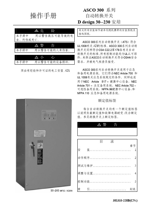
ASCO 300系列自动转换开关(ATS)符合 UL1008有关ATS的标准。ASCO 300系列自动转 换开关同样符合CSA C22.2第178条有关自动 转换开关的标准。所有控制功能均为UL认可部 件,来保证ASCO自动转换开关符合OSHA安全 需求,并被电气核查员接受。
ASCO 300系列自动转换开关适用于应急 和备用电源系统。它们符合NEC Article 700 和 UL 1008有关应急系统规定的条件。同样也适 用于NEC Article 517 – 健康中心设备,NEC Article 701 – 法定备用系统,NEC Article 702- 可选性备用系统,NFPA 99健康中心设备,和 NFPA 110 应急和备用电源系统。
RD 使用说明书

MOTOMAN专用数字式逆变焊接电源RD350使用说明书请务必将该说明书交到操作者手中A1301-02 1 / 108A1301-02在使用该设备以前,请操作者务必认真阅读本说明书,以掌握正确的使用方法。
感谢选用数字式逆变控制的高性能CO2 /MAG/MIG 机器人专用焊接电源“ RD350 ”。
在使用焊接电源以前,请仔细阅读本说明书,以掌握焊接电源的正确使用方法。
除此以外,还请参照送丝机构、焊枪、气体压力调整器等设备的“ 使用说明书”。
●为了确保本焊接机安装、维护点检、修理的安全性,须由熟悉焊接机、训练有素的人员或获得相关资格的人员进行操作。
●为了确保操作的安全性,本设备的操作人员必须充分掌握该使用说明书的内容,具有安全操作的知识及技能。
●请勿对本设备进行改装。
改装可能成为导致触电、受伤及机器故障等原因。
●在安全教育方面,希望用户参加焊接学会、焊接协会及相关学会、协会的总部及分部举办的各种讲习会,并积极参加焊接技术者、焊接技术师的资格考试。
●阅读完该使用说明书后,请将本书妥善保管于相关人员可随时看到的地方。
必要时,请再次阅读有关内容。
iiA1301-02 2 / 108A1301-02A1301-02 3 / 108安全注意事项1 额定规格2 安装和接线2.1 安装环境 . . . . . . . . . . . . . . . . . . . . . . . . . . . . . . . . . . . . . . . . . . .2-1 2.2 接地施工注意事项 . . . . . . . . . . . . . . . . . . . . . . . . . . . . . . . . . .2-1 2.3 必需的电源容量配备及接线规格 . . . . . . . . . . . . . . . . . . . .2-2 2.4 漏电断路器组合. . . . . . . . . . . . . . . . . . . . . . . . . . . . . . . . . . . . .2-3 2.5 电气系统的接线. . . . . . . . . . . . . . . . . . . . . . . . . . . . . . . . . . . . .2-4 2.6 焊接电压检出线的接线. . . . . . . . . . . . . . . . . . . . . . . . . . . . . .2-7 2.7 焊接保护气系统的连接. . . . . . . . . . . . . . . . . . . . . . . . . . . . .2-102.7.1 混合气及二氧化碳气体保护焊 . . . . . . . . . . . . . . . . . . . . . . . . .2-10 2.7.2 关于焊接用气体与气瓶的注意事项. . . . . . . . . . . . . . . . . . . . . .2-102.8 环境的整备 . . . . . . . . . . . . . . . . . . . . . . . . . . . . . . . . . . . . . . . .2-12 2.9 搬运注意事项 . . . . . . . . . . . . . . . . . . . . . . . . . . . . . . . . . . . . . .2-143 焊接准备4 焊接电源面板的操作方法4.1 焊接电源面板 . . . . . . . . . . . . . . . . . . . . . . . . . . . . . . . . . . . . . . .4-1 4.2 焊接电源面板的操作内容 . . . . . . . . . . . . . . . . . . . . . . . . . . .4-34.2.1 溶接法 (焊接方法)的选择 . . . . . . . . . . . . . . . . . . . . . . . . . . .4-3 4.2.2 使用者内容. . . . . . . . . . . . . . . . . . . . . . . . . . . . . . . . . . . . . . . . .4-7 4.2.3 P 参数的修改 ................................................................................... 4-7 4.2.4 C 参数的修改 ................................................................................... 4-8 4.2.5 D 参数的修改 ................................................................................... 4-9 4.2.6 条件记忆 . . . . . . . . . . . . . . . . . . . . . . . . . . . . . . . . . . . . . . . . .4-10 4.2.7 焊接保护气检查时间的调整 . . . . . . . . . . . . . . . . . . . . . . . . . . .4-10 4.2.8 送丝马达的选择 . . . . . . . . . . . . . . . . . . . . . . . . . . . . . . . . . . . .4-11 4.2.9 马达电流的监控 . . . . . . . . . . . . . . . . . . . . . . . . . . . . . . . . . . . .4-12 4.2.10 系统复位 . . . . . . . . . . . . . . . . . . . . . . . . . . . . . . . . . . . . . . . .4-12 4.2.11 面板操作锁的设定 . . . . . . . . . . . . . . . . . . . . . . . . . . . . . . . . .4-14⏹ 面板操作锁的设定方法 . . . . . . . . . . . . . . . . . . . . . . . . . . . .4-14 ⏹ 面板操作锁的解除方法 . . . . . . . . . . . . . . . . . . . . . . . . . . . .4-154.3 P 参数一览表.................................................................................. 4-16iiiA1301-024.4 C 参数一览表 ........................................................................... 4-174.5 D 参数一览表 ........................................................................... 4-205 焊接作业5.1 焊接条件的确认. . . . . . . . . . . . . . . . . . . . . . . . . . . . . . . . . . . . 5-15.2 焊丝的干伸长. . . . . . . . . . . . . . . . . . . . . . . . . . . . . . . . . . . . . . 5-15.3 焊接方向和焊枪角度. . . . . . . . . . . . . . . . . . . . . . . . . . . . . . . . 5-15.4 延长电缆接线时的注意事项. . . . . . . . . . . . . . . . . . . . . . . . . 5-26 使用时的注意事项6.1 异常检测功能. . . . . . . . . . . . . . . . . . . . . . . . . . . . . . . . . . . . . . 6-16.2 电源开关跳闸. . . . . . . . . . . . . . . . . . . . . . . . . . . . . . . . . . . . . . 6-36.3 焊接作业时的注意事项. . . . . . . . . . . . . . . . . . . . . . . . . . . . . 6-37 关于内置功能7.1 Pr(MB) 基板的 DIP 开关的设定............................................................ 7-17.2 Pr( CR ) 基板的 DIP 开关的设定........................................................... 7-28 维护及点检8.1 防尘过滤装置的清扫. . . . . . . . . . . . . . . . . . . . . . . . . . . . . . . . 8-28.2 保险管的更换. . . . . . . . . . . . . . . . . . . . . . . . . . . . . . . . . . . . . . 8-49 故障的诊断9.1 设定内容的确认. . . . . . . . . . . . . . . . . . . . . . . . . . . . . . . . . . . . 9-19.2 焊接部分的异常、原因及对策. . . . . . . . . . . . . . . . . . . . . . 9-39.3 电气回路部分的异常、原因及对策. . . . . . . . . . . . . . . . . . 9-6ivA1301-02 4 / 108A1301-02 10 机器人用接口的信号规格10.1 机器人用接口的信号规格. . . . . . . . . . . . . . . . . . . . . . . . .10-110.2 背面侧外部端子/Pr(IF)-008 端子的含义和功能. . .10-210.3 侦测功能用信号的含义和功能[选项基板Pr(OP)-003[RD350 机用]] .......................................... 10-411 接线系统图12 诊断功能12.1 诊断模式的起动. . . . . . . . . . . . . . . . . . . . . . . . . . . . . . . . . .12-112.2 焊接电源故障发生次数的确认. . . . . . . . . . . . . . . . . . . .12-212.3 故障履历的删除. . . . . . . . . . . . . . . . . . . . . . . . . . . . . . . . . .12-312.4 诊断模式的结束. . . . . . . . . . . . . . . . . . . . . . . . . . . . . . . . . .12-313 P 参数的说明(焊接特性调整)13.1 可调整的焊接特性. . . . . . . . . . . . . . . . . . . . . . . . . . . . . . . .13-113.2 起弧特性. . . . . . . . . . . . . . . . . . . . . . . . . . . . . . . . . . . . . . . . .13-213.2.1 起弧脉冲. . . . . . . . . . . . . . . . . . . . . . . . . . . . . . . . . . . . . . . .13-213.2.2 热启动条件. . . . . . . . . . . . . . . . . . . . . . . . . . . . . . . . . . . . . .13-313.3 熄弧特性. . . . . . . . . . . . . . . . . . . . . . . . . . . . . . . . . . . . . . . . .13-413.4 短路焊接特性. . . . . . . . . . . . . . . . . . . . . . . . . . . . . . . . . . . .13-613.5 脉冲焊接特性. . . . . . . . . . . . . . . . . . . . . . . . . . . . . . . . . . . .13-713.6 弧长恒定控制增益. . . . . . . . . . . . . . . . . . . . . . . . . . . . . . . .13-913.7 焊接电流输出特性. . . . . . . . . . . . . . . . . . . . . . . . . . . . . . .13-10vA1301-02 5 / 108A1301-0214 焊接电流校验功能14.1 什么是焊接电流校验功能. . . . . . . . . . . . . . . . . . . . . . . . 14-114.2 焊接电流校验功能的步骤. . . . . . . . . . . . . . . . . . . . . . . . 14-214.3 焊接电流校验功能的参数. . . . . . . . . . . . . . . . . . . . . . . . 14-615 机器人控制柜焊接机特性文件16 电弧监视功能的设定17 外部遥控操作17.1 气体检查. . . . . . . . . . . . . . . . . . . . . . . . . . . . . . . . . . . . . . . . . 17-117.2 使用者内容切换. . . . . . . . . . . . . . . . . . . . . . . . . . . . . . . . . . 17-218 服务部件表viA1301-02 6 / 108A1301-02 安全注意事项●在使用设备前,请务必认真阅读本使用说明书,掌握正确的使用方法。
保时捷 - 家庭电源管理器 - 安装手册说明书

02/2022Porsche、保时捷盾徽、Panamera、Cayenne 和Taycan 是 Dr. Ing. h.c. F. Porsche AG(保时捷股份公司)的注册商标。
德国印刷。
未经 Dr. Ing. h.c. F. Porsche AG(保时捷股份公司)书面授权,不得以任何形式翻印、摘录或复印本手册。
© Dr. Ing. h.c. F. Porsche AG(保时捷股份公司)版权所有Porscheplatz 170435 StuttgartGermany安装手册请务必保管好本《安装手册》,并在转售充电器时移交给新的主人。
由于各个国家/地区的要求不同,本手册的拇指索引标签中的信息也会不同。
为了确保您看到的拇指索引标签适用于您所在的国家/地区,请比较“技术数据”部分中的充电器产品编号与充电器铭牌上的产品编号。
其他说明有关安装基本壁挂支架和充电盒的信息以及保时捷充电器的电气安装的信息,请参考安装说明。
建议对您的车辆或本手册有任何疑问、建议或想法吗?请与我们联系:Dr. Ing. h.c. F. Porsche AGVertrieb Customer RelationsPorscheplatz 170435 StuttgartGermany装备由于我们一直都在不断进行创新与开发,因此您车辆的实际配置和规格可能与本手册中的保时捷图示或描述有所不同。
装备项目并不总是符合标准交付范围或特定于国家/地区的车辆配置。
有关改装装备的详细信息,请与合格的专业维修中心联系。
保时捷推荐保时捷中心来完成这项工作,因为他们拥有经过培训的维修中心专业人员,并且备有必要的零件和工具。
由于各个国家/地区的法律要求不同,您车辆上的装备可能与本手册中的描述有所不同。
如果您的保时捷安装了任何本手册中未描述的装备,有资质的专业维修中心将乐于提供相关的正确操作及保养建议。
人民电器 RDQH5Y系列双电源自动转换开关 使用说明书

SERIESR D QH5Y系列双电源自动转换开关符合标准:G B/T14048.11产品安装使用前,请仔细阅读使用说明书,并妥善保管,以备查阅。
前言感谢您使用本公司产品,诚愿本产品能给您的工作和生活带来效益和方便。
欢迎您在使用过程中提出宝贵的意见和建议。
我们将一如既往与您提供热心周到的售后服务。
若有任何疑问,请与我们的销售商或直接与制造商联系。
本说明书只提供参考,若有产品或版本升级变更,恕不另行通知,以实收产品为准。
感谢您的合作与支持。
1 概述1.1 适用范围RDQH5Y双电源自动转换开关(以下简称双电源),它适用于交流50Hz、额定工作电压400V、额定工作电流50A~125A的供电系统。
可根据需求或具体电路情况进行两路电源之间的切换选择。
本产品具有过载、短路、过电压、欠电压保护功能,同时还具备消防、双分和输出合闸信号功能。
产品适用于高层楼宇、商场、银行、医疗卫生等不允许停电的重要场所。
产品符合GB/T 14048.11标准。
1.2 正常工作条件与安装条件1.2.1 安装地点的海拔不超过2000m;1.2.2 周围空气温度上限不超过+40℃,且其24h内的平均值不超过+35℃,下限不低于-5℃;1.2.3 大气的相对湿度在周围最高温度+40℃时不超过50%,在较低温度下允许有较高的相对湿度,例如+20℃时达90%。
对于温度变化偶尔产生在产品上的凝露应采取特殊的措施;1.2.4 污染等级为3级;1.2.5 产品使用在无爆炸危险的介质中,且介质无足以腐蚀金属和破坏绝缘的气体与导电尘埃的地方。
1.2.6 产品安装在无冲击振动及无雨雪侵袭的地方,安装板与各方向倾斜度不超过5°;1.2.7 安装类别为III;1.2.8 产品安装场所附近的外磁场,在任何方向不应超过5倍的地球磁场。
注:如果上述条件不满足,订货时应与制造商协商。
极数(4P :四极 3P :三极)壳架等级特殊派生代号(双电源自动转换开关)企业代号2 产品型号及含义两进一出机构额定工作电流3 结构与原理3.1 结构RDQH5Y 双电源自动转换开关,主要由两台塑壳断路器、电动机、控制器和机械转动装置组成,该双电源为两进一出结构。
人民电器 RDSG系列三相干式变压器 使用说明书
RD SG系列干式变压器符合标准:J B/T 8750产品安装使用前,请仔细阅读使用说明书,并妥善保管,以备查阅。
-1-1.概述1.1适用范围RDSG 系列干式变压器为户内空气自冷式,适用于交流50或60Hz ,电压500V 及以下的电路中,是一般电器或照明灯常用的三相电源变压器,也可作为小型电源用。
2.产品特点和结构RDSG 系列干式变压器是运用美学思想设计的一款变压器,具有造型美观、性能稳定、损耗低、维护方便等特点。
该系列干式变压器是防护式,面板有电量及电源信号显示。
变压器为内接线,接线方便用电安全。
产品底部设有脚轮移动方便,除有电压、电源显示外,5kVA 以上容量的可增加轴流散热风机。
本产品按照JB /T 8750标准设计制造。
3.正常工作条件3.1海拔高度不超过2000m;3.2环境温度(-5~+40)℃,并考虑到因温度变化在产品表面产生凝露;3.3环境空气相对湿度不大于90%(25℃时);3.4安装场所无严重的振动和颠簸;3.5在无爆炸危险的介质中,且介质中无足以腐蚀金属和破坏绝缘的气体及导电尘埃的地方;3.6电源电压波型为实际正弦波,三相电源近似对称。
电压等级:kV 额定容量:kVA 干式三相变压器公司代号4 型号及含义S GRD-2-5 外型及安装尺寸5.1 R D SG 系列防护式干式变压器外型及安装尺寸(见表、图1、2);图1 图2规格型号额定容量联 接组标号RDSG-0.5kVA RDSG-0.75kVA RDS G-1k VA RDSG-1.5k VA RDSG-2k VA RDSG-2.5k VA RDSG-3k VA RDSG-4k VA RDSG-5k VA RDSG-7k VA RDSG-10k VA RDSG-15k VA0.5k VA 0.75k VA 1k VA 1.5k VA 2k VA 2.5k VA 3k VA 4k VA 5k VA 7k VA 10k VA 15k VA380V 380V380V380V 380V 380V 380V 380V 380V 380V 380V 380V36V 36V 36V 36V 36V 36V 36V 36V 36V 220V 220V 220V330×300×250330×300×250330×300×250330×300×250410×340×290410×340×290410×340×290450×400×300450×400×300505×450×350505×450×350505×450×350外型尺寸(m m)Y/yD/y Y/dD/d电压输入输出Y/yA×B×C-3-A B CX Y ZA B CX YZxyzD/DD/YCB Azx y 6. 绕组方式常用绕组方式分为以下几种ca b Y/YA B CXY Zxyz0ca b Y/Y 0A BCX Y ZY/Dcab a b cX Y Z xyzxyzb ca7. 使用说明7.1 打开包装箱,取出说明书及本产品,仔细阅读,以便正确使用;7.2 使用前,必须测试电路。
双电源自动转换设备TOQ3D说明书
Rated: voltage 220V 50/60HZNoted: power will be interrupted when Switching.Switch time<4SMax current: 63A.1. Dual power Automatic transfer switch can switch to Normal power or reserve power aut omatically. Please noted that the switch can’t turn on or turn off the generator. This switch Normal power first. If normal power on, the switch will switch to Normal power. If norma l power off, and reserve power on, the switch will switch to reserve power.2.WirePress the button to Automatic, the switch will switch to Normal power or reserve power au tomatically.Press the button to Manual, Then you have to switch the Direction manually.1.ApplicationTOQ3D is terminal type automatic transfer device. It’s suitable for 3 phases 4 wires (or 1 phase 1 wire) dual power grid with AC 50/60Hz, rated voltage 400V/230V and rated current up to 63A . When one power goes wrong (only test normal Phase A voltage and reserve Phase A voltage, o nly test loss voltage or loss phase),it will automatic connect one or several load circuits from one power to the other power automatically, to ensure normal power supply of load circuits.The automatic transfer switch conforms to IEC60947-6-1 and GB/T14048.112.Normal conditions for operation and installation:Environmental Temperature Condition:-5~+40°CInstallation site is not more than 2000 meters above sea level.Pollution Level: Grade 3Installation Category: 3Vertical installation or horizontal installation4. Main parameterRated Current Ie A 6,10,16,20,25,32,40 50, 63Electrical Appliances Class CBUse Category AC~33BTripping Current 5~10In (Type C), 10~15In (Type D), Rated voltage Ue 220V (2P),380V (3P or 4P)Rated frequency 50/60HzRated short circuit connecting ability Icm (Peak) 9.18KA 6.615KA Rated short circuit breaking ability Icn (effective value) 6KA 4.5KA6. Terminal wiring diagram7. Installation and wiringATSE can be installed in power control cabinet directly. Users can wire after ATSE installation (refer to design and use). As per current value use suitable conductor to connect the mains side (t op terminal) and load side (bottom terminal) of MCB of normal electric power and standby elect ric power. In-phase parallel connection at load side, and ensure the phase sequence of normal electric power a nd standby electric power must be accordant (Wire as per A,B,C,N sequence). For 3 poles ATS E should add one conductor with section not less than 0.3mm2 to connect theneuter line of pow er supply correctly, thus ATSE can work properly. For 4 poles or 2 poles ATSE, N pole of norm al electric power and standby electric power should be connected to N pole of MCB respectively . In addition, when install ATSE please ground reliably at grounding mark.8. Use1) Normal use, please set the switch of controller at Automatic Function. Under Auto working the controller of ATSE monitor normal electric power and standby electric power and display runn ing status of ATSE. When Normal power cut, novoltage, failure, ATSE will transfer load autom atically from normal power to standby power. If normal power get right, ATSE will transfer loa d automatically from standby power to normal power. The luminous diode on switch panel indic ate switch off situation.2) If you don’t adopt automatic transfer or need other manual operation please set the controlle r at manual. Under manual operation the controller stop work, and manual operation can make t he breaker on off, and the switch doesn’t transfer automatically.3) When ATSE is short circuit or over load, The MCB of ATSE will protect tripping. If power display normally the handle of MCB is switching on. If the MCB has protected tripping users sh ould set at manual and operate the switch to dual separating brake by hand, and check the reaso n of trip. After trouble clearing please set the controller at auto again to operate.4) When ATSE transfer to auto from manual, if normal and standby power are normal ATSE w ill prior connect normal power to load (even if load connected standby power ago)9. Matters need attentionWhen users test or operate please follow relative rules and pay attention to the following matter s to ensure use our ATES correctly.1)Neutral conductor N can’t be connected in wrong way, must connect reliably, otherwise ATSE can’t operate properly, even burn controller and motor.2)The protective grounding of ATSE must be connected reliably to ensure safety.3)Detection sampling signal for controller work power and main power supply is taken from Po wer supply side of main circuit, and work power of auxiliary connection terminal used for conne ct indicator is taken from main circuit, so can’t have voltage test between spare terminals (unless dismantle the secondary wires). Can have power frequency voltage test between main circuit and shell or between secondary auxiliary terminals and shell.10. Simple troubleshootingWhen users find fault can request professional to test and deal with. Keep Away for Safety whe n operate. Or contact our Specialized Service Departments.1) Double Power are both switched on, but ATSE can’t transfer automatically1 Check Auto/manual should be in automatic position.2 Check if incoming line is correct or not, if phase sequence is accordance or not, and wiring is s olid and reliable or not.3 Check if the fuse is burned on not.2) Double power are both switched on, ATSE standby power is switching on.4 Check if normal power incoming line has voltage or not.5 Check Commonly used insurance6 Check if external light is connected in wrong way or not。
晟光3相混合备电源说明书
LOWER COSTBLACK-START CAPABLE7.2 electrical outages are reported worldwide in a typical month. The average in Europe is of course smaller,nevertheless there are also many grid failures in Europe.But this is something you don’t have to worry about anymore! During blackout, the 3-phase Hybrid is capable of supplying selected house loads up to 9.9 kW, even unbalanced. That’s like 50 TVs , 1000 light bulbs or even 40 fridges full of beer!The best thing about it? No external backup box is needed. More power. More security. Less costs.Available withSH 5.0 / 6.0 / 8.0 / 10 RT Switch time backup mode< 20 ms Energize loads up to 3.3 kW / phase Less components neededsave up to 1000 €ALWAYS ON -EVEN OFF GRIDSUNGROW’S BACKUP FUNCTION - WATCHINGSOCCER GAMES, NO MATTER THE CIRCUMSTANCES!POWERWHENEVER YOU NEED ITand all loads connected to the backup port will get a seamless transition into backup mode . Only loads not connected to the backup port experience the black out.The 3-phase Hybrid can route up to 3.3 kVA per phase from the grid to the backup port on a permanent basis. For regular grid-parallel operation, this allows the inverter to have all loads supplied by the grid, even the ones connected to the backup port.BACKUP FUNCTION?YES WE CAN!as backup loads (orange) are powered by the grid. Both circuits can share the same distribution box but need to be protected by their own MCCB.GRID PARALLEL OPERATIONBACKUP MODEREAL INDEPENDENCE REAL BENEFITSFULL COMPLIANCEThe 3-phase Hybrid fully complies with the VDE-AR 2510-2 regulation. All required security standards for stationary electrical energy storage systems intended for connection to the low voltage grid are met completely.GRID FAILURE?Nothing to worry about! In case of a blackout the 3-phase Hybrid will automatically switch into backup mode - you won’t even see the light flicker. Within less than 20 ms a bypass switch will open and up to 9.9 kW of loads connected to the backup port will be supplied by the battery and PV.RELIABLE & COST SAVINGOnce the grid is back online the 3-phase Hybrid will reconnect safely and reliably. This process of disconnecting and reconnecting doesn’t require any external backup box or manual work. The needed bypass switch is already included inside the inverter. BATTERY CHARGING IN BACKUP MODE? During an outage, the 3-phase Hybrid will use excess PV energy to charge the battery.After an overnight blackout with an empty battery in the morning, the 3-phase Hybrid will recharge the battery with the first beams of light. Ready for the next blackout.BACKUP FOR ALL - HOW DOES IT WORK?MORE ANSWERSANDREA POLINIProduct Manager Hybrid SolutionsSungrow GermanyAre backup loads supplied by the grid during normal operation? Yes, during normal grid paralleloperation the backup port is directly bridged to the grid port. This way the loads are supplied by the grid just like the rest of the house loads.12345678Can the battery also be charged by the grid?Yes, a forced charge of the battery can be scheduled in the iSolarCloud app. The scheduled battery charge will take energy from the grid and from PV if available.Which batteries are compatible with the 3-phase Hybrid?The following high voltage batteries are compatible: LG Chem RESU 7H and 10H type R.BYD Battery Box Premium HVM and HVS as well as BYD Battery Box HV.Is a new distribution panel required to connect loads to the backup port?No, the existing house distribution panel can be rewired. Just install a30 mA RCD and an MCCB with 20 A for SH5.0RT, 32 A for SH6.0RT and 63 A for SH8.0RT and SH10RT for the backup connection.Is it possible to set a reserve ofbattery SOC in case of grid outage? Yes, using the iSolarCloud app, it can be configured how much batterypercentage should be kept as reserve. This ensures backup load supply is always available in case you need it.Will PV still be available during grid outage?Yes, the PV will supply the backup loads, any excess PV will charge the battery. If the battery is full, the inverter will limit the production to match the load consumption.What if an overnight outage occurs and the battery discharges while there is no PV?The inverter will shut down and wait for the sun to rise. As soon as PV energy is available the inverter will turn on and start charging the battery and supply backup loads autonomously.Is it possible to connect one single phase to the backup port?Yes, one single phase up to 3.3 kW can be connected to the backup port like a single power socket. N and PE shall also be connected like in a normal circuit.。
Q开关电源使用说明书
Q开关电源使用说明书声光Q开关电源使用说明书(适用于QSD5027、QSD7527)桂林市飞鹰激光应用技术有限公司欢迎您使用我公司生产的QSD系列Q开关电源。
在使用QSD系列Q开关电源之前,请您务必仔细阅读本使用手册。
本手册适用于QSD系列标准产品。
对于用户有特殊要求的特制产品,请仔细阅读手册中另附的特别说明。
请您打开包装箱,核对随机附件。
电源线一根15芯计算机针式插头一只Q9插头一套目录一、简介 11.概述................... 错误!未定义书签。
2.型号说明............... 错误!未定义书签。
3.主要性能和技术指标..... 错误!未定义书签。
二、工作原理及结构. . . . . . . . . . . . . . . . . . . . . . . . . . . . . . . .. 31.Q开关元件结构及工作原理错误!未定义书签。
1.1.结构 .............. 错误!未定义书签。
1.2.Q开关关断激光原理.. 错误!未定义书签。
1.3. Q开关进行Q调制..... 错误!未定义书签。
1.4.Q开关的等效阻抗... 错误!未定义书签。
2.Q电源结构与原理........ 错误!未定义书签。
2.1.开关电源及射频功率的调节. 错误!未定义书签。
2.2.射频单元.......... 错误!未定义书签。
2.3.主控单元 (8)2.3.1.控制电源 (8)2.3.2.控制方式 (8)2.3.3.调制脉冲及出光控制有效电平的设置122. 3. 4. 保护逻辑 (12)2.3.4.1.超温保护 (12)2.3.4.2.外控保护 (12)2.3.4.3.反射保护 (13)2.4.对外接口 (13)2.5.控制面板........... 错误!未定义书签。
2.5.1.数显表……………………………… ..17 2.5.2.RUN/STOP指示灯 (17)2.5.3.ALARM(报警)指示灯 (18)2.5.4.TEST(测试)指示灯 (18)2.5.5.M1、M2、M3 指示灯 (18)2.5.6.按键说明 (18)2.5.7.电源开关 (20)三、电源与Q开关元件的阻抗匹配 20四、安装及操作说明 211.安装条件 (21)2.电气安装连线 (21)3.操作流程说明 (23)五、异常现象释疑…………………………………………. .. 23附图 (26)一、简介1.概述QSD系列Q开关电源是针对不同的应用领域精心设计的高品质的声光Q开关(Acousto-Otipc Q-switch)驱动电源。
人民电器 RDCPSS 系列双电源自动转换开关电器 使用说明书
R D CPS系列控制与保护开关电器符合标准:GB/T14048.9产品验收及注意事项当您收到订购人民电器集团生产的RDCPS系列控制与保护开关电器后,请开箱检查以下各项:①请在开箱后全面检查RDCPS的产品外观,如发现问题请及时与供货商联系。
②请核对RDCPS系列产品的型号、规格和铭牌是否与你的订货要求一致,如发现有问题请及时与供货商联系。
③本控制与保护开关电器系列产品在使用时不能超出其铭牌所标出的内容要求,否则可能引起损坏;超出该产品保护范围使用 ,可能引起危险,还可能导致负载烧坏或损坏。
④产品在安装、运行、维护之前,必须熟读本使用说明书,以保证正确使用。
不正确的安装和配线连接不但会损坏产品,还可能导致人身伤亡等事故的发生。
⑤不要将本产品安装于含有爆炸性气体的环境里,否则有引发爆炸的危险。
⑥安装在没有雨雪侵袭或潮湿以及强磁场的地方。
⑦必须由具有专业资格的人员进行配线作业和维护。
⑧严禁对本产品进行改造,以及按键随意设置或粗暴操作,否则,可能会损坏产品,以及产品不能正常运行或不在有效的保护范围内,导致设备损坏。
⑨配线时,应确保压线牢固可靠,否则,压线松动容易造成接点处打火、过热,并可能会引发火灾事故。
⑩产品使用前,请核对产品本身的参数是否与保护的设备或线路参数一致。
否则,请根据实际运行的设备或线路的参数设置产品的相关参数。
一、适用范围1.1 性能及用途RDCPS系列控制与保护开关电器(以下简称RDCPS),主要用于交流50Hz (60Hz)、额定工作电压至400V、主体额定电流自6.3A至125A、智能控制器可调工作电流自0.4A至125A、 控制电机功率自0.05kW至55kW的电力系统中接通、承载和分断正常条件下( 包括规定的过载条件)的电流或电压,也能够接通、承载一定时间和分断规定的非正常条件下(如短路、欠压等)的电流或电压。
RDCPS采用模块化的单一产品结构型式,集成了传统的断路器(熔断器) 、接触器、过载 ( 或过压、 断相等 ) 保护继电器、起动器、隔离器、电机综合保护器等主要功能,具有远距离自动控制和就地直接入力控制功能,具有面板指示及机电信号报警功能,具有过压欠压保护功能,具有断相缺相保护功能,具有体积小、可靠性高,具有短路分断能力高、飞弧距离短等优点、具有各种特性内部自行良好配合的时间-电流保护特性 ( 反时限过载长延时保护、短路短延时保护、 瞬时短路保护及快速瞬时短路保护四段式保护特性 ),根据需要选配功能和/或功能模块,即可为各种电力线路 (如电机的频繁或不频繁起动以及配电电路负载) 提供完善地控制和保护功能,且动作精确,可避免不必要的停电,提高供电可靠性。