XBC系列柴油机消防泵
阳光泵业XBC系列柴油机消防泵组说明书

阳光泵业XBC系列柴油机消防泵组说明书(本文来源阳光泵业)一、概述XBC型柴油机消防泵组是本公司根据国内建筑消防用泵的市场需求和使用特点而自行研制生产的新产品。
该系列产品具有高效率、运转寿命长、高可靠性(不存在较长时间停用后启动咬死的故障),是目前国内适应建筑工程消防,喷淋设施用泵的首选产品。
产品性能符合GB6245-2006《消防泵》性能要求和实验方法,经国家消防装备质量监督检测中心测试,产品达到国内领先水平,获上海市消防局审批认可。
该产品可供输送80℃以下不含固体颗粒的清水或物理化学性质类似与水的液体之用。
在满足消防工况的前提下,兼顾生活、生产给水的工况要求。
产品既可用于独立消防给水系统,又可用于消防、生活共用给水系统,还可用于建筑、市政、工矿、给排水、船舶、野外作业等场合。
XBC柴油机消防泵与电器仪表等设备安装在一起整套组合,具有功能齐全,自动化程度高,结构紧凑,故障自动报警及接受启动信号,自行完成起动程序,能快速投入全负荷运行。
机组可按需求选配减振器、橡胶挠性接头、排气口配波纹管消音器。
在燃料不足、蓄电池电压低、润滑油温度高、超速等,备有报警装置,确保柴油机低温环境起动。
整个系统安全可靠,使用方便。
二、产品特点1. 电泵为主消防泵,可以根据消防情况自动起动;2. 配备稳压泵恒定管网压力;3. 柴油机泵为备用消防泵,消防无电源情况下自动起动;4. 电泵出现故障时柴油机泵起动;三、结构说明XBC型柴油机消防泵组根据GB6245-2006《消防泵》的标准要求,主要由泵体(1)、泵盖(2)、叶轮(3)、轴(4)、密封环(5)、轴套(8)、及悬架轴承部件(12)等所组成的。
XBC型柴油机泵的泵体和泵盖的部分,是从叶轮背面处剖分的,即通常所说的后开门结构形式。
其优点是检修方便,检修时不动泵体,吸入管路,排出管路和电动机,只需拆下(加长)联轴器的中间联接件,即可退出转子部件进行检修。
泵的壳体(即泵体和泵盖)构成泵的工作室。
XBC 型柴油机消防泵 安装使用说明书

XBC 型柴油机消防泵安装使用说明书XBC型柴油机消防泵安装使用说明书造制械机佳立湖南司公有限湖南立佳机械制造有限公司Hunan Perfect Industry Co., Ltd.1一、消防泵型号说明XBC200-670B设计流量:626.4m3/h扬程:1.15MPa水泵出口直径:DN200mm配套柴油机型号及功率:12V135DAZD,315KW(430HP)二、调试前检查工作1.安装检查1.1安装位置检查1.1.1泵房内的设备布置应保证安装、运行、管理维修等工作的方便。
一般泵端或泵侧与墙之间的净距?1.5m,两排泵之间净距?2m。
1.1.2 两台泵之间的净距?0.75m,泵前端操作通道宽度?1m,多级泵?1.8m,泵前端维修通道?1.25m。
———————————————————————————————————————————————造制械机佳立湖南司公有限21.1.3 泵房有起吊设备或有至少能竖起三角架等吊装设备的空间,通风及光线良好(晴天的白天不用开灯能满足操作维修需要的光线)。
1.1.4泵组的安装高度要满足有效汽蚀余量。
1.2安装基础检查1.2.1安装基础必须是一个整体。
1.2.2对于电动机直连的型式,基础自身量应为设备重量的3倍以上,对于发动机直连的型式,基础自身的重量应为设备重量的5倍以上(混凝土的比重为:1立方米重1.8-2.45吨,平均重2.12吨)。
1.2.3在两层以上墙面板安装时,基础中心和深中心一致或套在两根梁上,并尽可能接近柱式墙壁。
1.2.4 泵组底架与基础混凝土之间距离应?10mm,且基础表面要保留凹凸不平的原样。
1.2.5基础的长(宽)应比机组底架长(宽)多出200-240mm,基础表面比地面高?200mm,地脚螺栓预留孔一般为100x100mm方孔。
1.2.6基础外观不不应有于裂纹、烽容、容洞、露筋等缺陷。
1.2.7基础的中心线需与机组底架中心线重合(偏差小于2mm)。
XBC-XBD型立式长轴消防泵样本

水泵型号
XB2.1/10~ XB10.5/10 XB12.6/10~ XB16.8/10
XB1.8/20~XB9/20 XB10.8/20~XB16.2/20 XB1.6/30~ XB9.6/30 XB11.2/30~ XB12.8/30 XB2.1/40~XB10.5/40
XB12.6/40 XB2.5/60~ XB10/60
7、配用动力: 1)、配用普通立式电机直联驱动。 2)、配用带推力轴承的立式电机直联驱动。 3)、配用柴油机通过直角齿轮箱变速驱动。 4)、配用卧式高速电机通过直角齿轮箱变速驱动。
液体种类 主要零件
喇叭口
主要零件材质表
清水
Ⅰ
Ⅱ
HT200
HT200Ni2Cr
海水 Ⅲ
321 或 316L 不锈钢
叶轮
HT200 或 ZG230-450 ZG1Cr18Ni9Ti ZCuZn16Si4 或 316L 不锈钢
XB3.6/20
36
XB5.4/20
54
XB7.2/20
72
XB9/20
20
90
XB10.8/20
108
XB12.4/20
124
XB14.4/20
144
XB16.2/20
162
XB1.6/30
16
XB3.2/30
32
XB4.8/30
48
XB6.4/30
64
30
XB8/30
80
XB9.6/30
96
XB11.2/30
33
75
47
110
27
45
40
75
XB6.6/100
66
XBC 型柴油机消防泵 安装使用说明书

1.6 排气管安装检查
1.6.1 排气管道的重力不应作用于柴油机的排气口上。 1.6.2 排气管上必须安装膨胀波纹管,消声筒(装室内)且其口径要比柴油机的排气口大。 1.6.3 排气管道应尽量短、减少弯头(一个弯头相当于 10 倍直径长度)。 1.6.4 排气管末端需按至室外,且必须有防水装置,排气管末端应用下倾斜(⊿1:5)。 1.6.5 排气管应用保温材料包裹。 1.6.6 排气管穿过墙体时应按下图施工。
湖南立佳机械制造有限公司
2
1.1.3 泵房有起吊设备或有至少能竖起三角架等吊装设备的空间,通风及光线良好(晴天的白
湖南立佳机械制造有限公司 天不用开灯能满足操作维修需要的光线)。
1.1.4 泵组的安装高度要满足有效汽蚀余量。
1.2 安装基础检查
1.2.1 安装基础必须是一个整体。 1.2.2 对于电动机直连的型式,基础自身量应为设备重量的 3 倍以上,对于发动机直连的型式, 基础自身的重量应为设备重量的 5 倍以上(混凝土的比重为:1 立方米重 1.8-2.45 吨,平均重 2.12 吨)。 1.2.3 在两层以上墙面板安装时,基础中心和深中心一致或套在两根梁上,并尽可能接近柱式 墙壁。 1.2.4 泵组底架与基础混凝土之间距离应≥10mm,且基础表面要保留凹凸不平的原样。 1.2.5 基础的长(宽)应比机组底架长(宽)多出 200-240mm,基础表面比地面高≥200mm, 地脚螺栓预留孔一般为 100x100mm 方孔。 1.2.6 基础外观不不应有于裂纹、烽容、容洞、露筋等缺陷。 1.2.7 基础的中心线需与机组底架中心线重合(偏差小于 2mm)。 1.2.8 机组底架水平偏差小于 1.5/1000。 1.3 减震检查
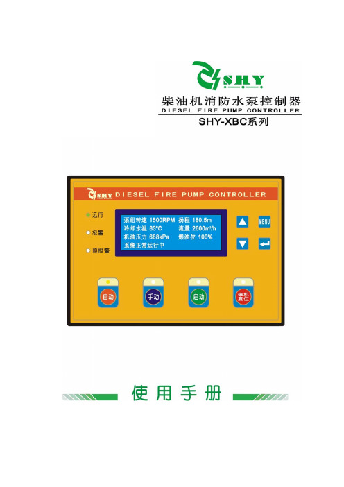
柴油机消防水泵控制器SHY-XBC使用手册
广州胜业智能科技有限公司
按键名称
SHY 系列智能控制系统
功能描述
确认键
在设 置菜单下,按此键并可在参数 设置中确认设 置信息,即返回当前设置的参数项目序号上。
上翻/递增键
按下此键进行菜单查看/向上翻屏,在设置参数过 程中向上移动光标及递增光标所在位的数字。
下翻/递减键
按下此键进行菜单查看/向下翻屏,在设置参数过 程中向下移动光标及递减光标所在位的数字。
应用环境 周围温度 周围湿度 储藏条件 海拔高度 防护等级 详细尺寸 外形尺寸 开孔尺寸 重量
-20 至 70℃ 10 至 95% RH(不淋露) 温度:- 30 至+80℃ 低于 2000m 前面板 IP55
W232mm x H163mm x D52mm W213.5mm x H144.5mm 1.4kg
其主要特点如下:
¾ 液晶显示(蓝色屏)LCD 为 192x64 点阵式,带背光灯方便数据观测;
¾ 中文显示,信息全面,设定一目了然,8 个轻触式按键操作;
¾ 精密采集柴油机水泵机组的各项参量:
泵组转速 SPD 单位:RPM 扬程 H单位:m来自冷却水温 WT 单位:℃
流量 F
单位:m3/ h
机油压力 OP 单位:kPa 燃油位 FL 单位:%
第3页
共 31 页
广州胜业智能科技有限公司
一.概述
SHY 系列智能控制系统
SHY 系列柴油机水泵智能控制器采用高性能的微处理技术,结合高可靠性 的设计,具有很高的可靠性及稳定性,实现了多种参数的精密测量、报警保护 值设定等功能;适用于柴油机水泵机组自动化控制系统,可实现泵组的手动、 自动开机/停机,数据测量、报警保护等控制功能。
SHY 系列柴油机水泵智能控制器采用 192X64 大屏幕液晶(LCD)显示, 所有参数可从控制器前面板设定。其结构美观紧凑、接线简单,运行可靠,广 泛应用于各类型水泵机组自动化控制系统。
上海东方泵业XBC柴油机消防泵组

1XBC XBC type diesel fire fighting pump unitGeneral6hApplicationOperation condition15350L/S 50180mP2.5Mpa 80Flow capacity Head Maximum operation pressure of system Temperature of medium Our diesel fire fighting pump unit is a new generational product which developed by our company combined with eign advanced technology. This fir e fighting pump unit avoids to use r aising speed tank, and equipped with fuel tank, oil tank and unit. Pump unit has small cubage, light weight, high efficiency, low noise, small convenient maintenance, beautiful outline and so on.It mainly applies in airport, oil storage, port, petroleum chemical industrial fire fighting project, pressing fire fighting pipe net, supplying water automatically, other supplying or draining water system and so on.XBC type diesel fire fighting pump unitXBC XBC performance parameter table2XBC XBC performance parameter table3XBC Performance curve drawing for XBC fire fighting pump H(m)(%)12011010090807060504080706050543(N PS H)r (m )Pa(KW)4030201001020304014410872360XBC10/258/255/25XBC8/307/406/50B02H(m)9070503010100150200Q(L/s)3Q(m /h)Q(L/s)3Q(m /h)303540455055(%)Pa(KW)757065604020B01H(m)120116112108104100969288848076726864(%)807060504030201001020304050607004080120160200240Q(L/s)3Q(m /h)02550751000100200300360Q(L/s)3Q(m /h)(N PS H )r (m )5432Pa(K W)60504030H(m)Pa(KW)806040100806040XBC10/5010/4010/308/558/45B03XBC9/708/607/706/80XBC10/60B05H(m)1601401201008060180140100602006012018020024030036010080604020Q(L/s)3Q(m /h)(%)(NPSH)r (m)908070605432H(m)8060402001601208040Pa(KW)Q(L/s)3Q(m /h)010203040506070809010011004080120160200240280320360400(m)XBC8/8012/8016/80B064(%)XBC12/12018/12012/120-Z18/120-ZB09H(m)0Q(L/s)3Q(m /h)20040060050100150(%)Pa(KW)80706015010050H(m)2402101801501209060Pa(KW)36030024018012003060801001201400100200300400500Q(L/s)3Q(m /h)(NPSH)r(m)(%)807060504030753XBC11/13516/135B10H(m)220200180160140120100(%)908070605005060708090100110120130140150160170200250300350400450500550600Q(L/s)3Q(m /h)8765432330300270240210180150P a (K W )(N P S H )r (m )XBC12/12018/12012/120-Z 18/120-ZH(m)110100Pa(KW)00180360540720040801201602002403Q(m /h)Q(L/s)(NPSH)r(m)(%)48020406080H(m)Q(L/s)3Q(m /h)56111166222200400600800P a (K W )(N P S H )r (m )43230022515075XBC13/10016/100B07H(m)20018016014012010080602001601208040(%)(NPSH)r(m)8070605040308642010203040506070809010011004080120160200240280320360400Q(L/s)3Q(m /h)Pa(KW)XBC11/15010/1505XBCXBC12.5/35010.5/320B14 DrawingB14XBC9/2108/200B13H(m)957555(%)755025002004006008000100200Q(L/s)3Q(m /h)Pa(KW)300200100Q(L/s)3Q(m /h)0400800120016000100200300400H(m)70(%)806040200Pa(KW)6DrawingB13XBC Performance curve drawing for XBC fire fighting pumpXBC XBC outline installation drawing7XBC XBC outline installation drawing8XBC XBC outline installation drawingXBC XBC outline installation drawingXBC XBC outline installation drawingXBC XBC outline installation drawingXBCXBC XBC outline installation drawingXBCFlange dimension drawing of XBC inlet & outletXBC1 Flange dimension drawing(table 1) of XBC inlet & outletPLCB B AA0~15C C BPLCB B AA0~15C C B15C PLCThe structure of this automatic control systemPressure inspecting set of pipe netAutomatic control screenWire remote control operating indicating screen of central control roomThe structure of the fire fighting pump unit in this automatic control systemSingle diesel fire fighting pump unitJockey pump and diesel fire fighting pump unitJockey pump, electric fire fighting pump and diesel fire fighting pumpThe operating procedure of fire fighting pumpControl single diesel firefighting pump unit (Single unit type)1.The pressure of pipe net reduce to less than the set point, it will start diesel fire fighting pump unit automatically when automatic control screen receives the signal;2.After PLC judges start is successful, it will control to improve unit's revolving speed until it gain the full-load operationcondition;3.During fire fighting pump operating, control system inspects the operation parameter of unit automatically. If there is malfunction, it will give sound and light alarm.Control jockey pump and diesel fire fighting pump unit (Two units type)1.The pressure of pipe net reduce to less than the set point B(B<A), it will start jockey pump automatically whenautomaticcontrol screen receives the signal;2.The pressure of pipe net raise to larger than the set point A, jockey pump will stop automatically after delaying for 0-15 seconds;3. The pressure of pipe net reduce to less than the set point C(C<B), it will start diesel fire fighting pump unit automatically when control screen receives the signal;4.After PLC judges start is successful, it will control to improve unit's revolving speed until it gain the full-load operationcondition;5.During fire fighting pump operating, control system inspects the operation parameter of unit automatically. If there is malfunction, it will give sound and light alarm.Control jockey pump, electric fire fighting pump and diesel fire fighting pump(Three units type)1. The pressure of pipe net reduce to less than the set point B(B<A), it will start jockey pump automatically whenautomaticcontrol screen receives the lower pressure signal;2. The pressure of pipe net raise to larger than the set point A, jockey pump will stop automatically after delaying for 0-15 seconds;3.The pressure of pipe net reduce to less than the set point C(C<B), it will start electric fire fighting pump unitautomatically when control screen receives the signal;4.If the pressure of pipe net is less than C after electric fire fighting pump unit starting for 15 seconds, automatic control screen will give order to start diesel fire fighting pump unit automatically;5.After PLC judges start is successful, it will control to improve unit's revolving speed until it gain the full-load operationcondition;1.During fire fighting pump operating, control system inspects the operation parameter of unit automatically. If there isMalfunction, it will give sound and light alarm.Automatic control system can give alarm as followingsStart failureIf it the start revolving speed is less than the idle speed for three times after diesel fire fighting pump received start signal, it is start failure,and will give sound light alarm. Employee should check and remove the malfunction, then start unit by manual.Electric fire fighting is sart failure."Water temperature is high","oil pressure is low","fuel level is low","over speed","start accumulator is malfunction", "screen accumulator is malfunction in diesel fire fighting pump unit.It should shut off emergently when it is over speed.Stop condition, if the select switch of automatic control screen sets on automatic position, it may finish following functions Diesel's accelerator rod replaces start position automatically.Ontrol system charges accumulator automaticallyThe power of each automatic control screen is 220V, 20A.There is operation,malfunction indicator light and" start" button of fire fighting pump unit on the operating screen of central control room. Press start button, it may start electric fire fighting pump unit or diesel fire fighting pump unit by wire remote, and can get full-load work condition automatically.Supply scopeMonitoring plant of pipe net pressure;Automatic control screen;Operating screen of central control room(If there isn't it in system design, we won't supply it);The control wire, cable from automatic control screen to each control point;Indicator light, button, relay and so on.Note: The dynamic cable isn't in the supply scope which from jockey pump's control panel to motor, andfrom start panel of electric fire fighting pump unit to motor.G J F T A7F UJ KX D C 1K C31K M 33K M 34K MQ MQ JM34K M 33K M 31K M 32K M 1K M 33K M 34K M 1S Q 2K M 3K M 4K M 34K M 7K M8K M 9K M 10K M 11K M 15H 16H 17H 18H 19H 20H 21H 22H 23H12K M 13K M 14KMGJ F TA7F UJ KX D C1K C31K M 33K M 34K MQ MQ JM34K M 33K M 31K M 32K M 1K M 33K M 34K M 1S Q2K M 3K M 4K M 34K M7K M8K M9K M 10K M 11K M 15H16H 17H18H19H20H21H22H23H12K M 13K M 14K MGeneratorvoltage adjuster AccumulatorStarterstart relay accelerograph actuatorstart dieseladd accelerographdecrease accelerograph stop dieselbrake electromagnetismelectrical source indicationautomatic control screen Diesel automatically Electricpump automatically Jockey pump operation Electric pump operationDiesel operationElectric pump failure Diesel failureAnnunciatorstart dieseladd oildecrease oilstop diesel pumpChargeAnnunciator system operationDiesel automatically Electric pump automaticallyJockey pump operation Electric pump operation Diesel operation Electric pump failureDiesel failurestart jockey pumpstart electric pumpStandbysystem operationDiesel automatically Electricpump automaticallyAccumulator failurelow oil pressure High water temperaturelow fuel level Over speed Diesel failure Electric pump operationDiesel operation Electric pump failure Jockey pump operation low fuel level the most level ofaccelerograph the start level of accelerographaccumulator failurepipe net pressure P1electric pump feedbackelectric pump automaticallyjockey pump feedback High oil temperaturehigh water temperaturelow oil pressureremote control diesel pump start electric pump system reposition stop jockey pumpstart jockey pumpSilencerTestStandbystop diesel pumpdecrease oiladd oilStart dieselSystem automaticallyMeasuring speedswitchDiesel automatically Revolving speedgaugePLCelectrical sourceelectrical sourceof switchUPSelectrical sourcecivil electricity indication charger AC 220V electrical sourcepipe net pressure P2pipe net pressure P3pipe net pressure P4Standby20400.30.13753515InstallationThe work before installation1. Check water pump and motor;2. Prepare installation tool and hoisting instrument;3. Check the level of base.The order of installation1.The pump unit have fixed and adjusted when it get to the station, it may not unload unit to find flat base, so it'sconvenient for installation.2. Put the base frame on the base, and put wedge-shaped iron under the foot bolt, block up the base to 20~40mm, it can Fill Grout after adjust the level.e level gauge to check the level of base;4.Put water pump and motor on the baseplate;5.Adjust the level of pump's shaft, install the motor after adjustment;6.Put ruler on the coupling, check if the axial leads of water pump and motor are superposition.Start and stopStart:1.Check the revolving direction of motor is right or not;2.Fill water in the pump or leading water by vacuum pump ;3.Close the gate valve of discharge pipe;4.After finished above process, switch on electric source, then open the gate valve on the discharge pipe untilthe rotor got normal revolving speed, and adjust to the required work condition.Stop1.Shut off the gate valve of discharge pipeline slowly, cut off the electrical source;2.If the ambient temperature is lower than the freezing point of liquid, we should discharge all of liquid in the pump, to Avoid frostbite;3.If pump keep stop for long time, we should discharge all of corrosive liquid in pump, and disassemble all of parts toclean, especially for seal cavity. It's better to assemble them after cleaning, besides we should lubricate them to Rust. OperationObserve the data of gauge and the bearing's temperature during pump keeping operation, the limit temperature of bearing shouldn't more than 75, and should less than ambient temperature 35;The normal leakage in the stuffing room is 15ml/minute;The oil level of bearing should keep on the normal position;If the seal ring is wore out, we should replace it in time;Pay attention to whether there is noise or not when pump is running, if there is abnormal state, we should remove it or stop to check it duly.Troubleshooting Malfunction ReasonWater pump couldn't discharge waterFlow capacity of water pump isn't enough The power is too largeNoise and shake Water pump leaks water a. The valve of inlet and outlet isn't open,inlet pipeline and flow passage of impelleris blocked;b. The revolving direction of motor isn'tright, motor is short of phase and revolvingspeed is slow;c. Suction pipe leaks gas;d. Pump isn't full of liquid, there is air inpump chamber;e. There isn't enough water in inlet, theSuction head is too high and the bottomvalve leaks water;f. The resistance in pipeline is too large,the Type of pump isn't suitable.a.Check and remove the block;b.Adjust the direction of motor, tighten thejoint of motor, and check electrical part;c.Tighten every seal surface and dischargeair;d.Open pump upper cover or opendischarge valve to discharge air;e.Stop unit to check and adjust;f.Reduce elbow of pipeline, select pumpAgain.a.Check it according to the reason thatwater Pump can't discharge water;b.Pipeline, flow passage of pump orimpeller is blocked, sediment of scale,valve aperture isn't enough;c.Voltage is too lower;d.Impeller is wore out.a.Remove it according to the reason thatwater pump can't discharge water;b.Remove block, adjust valve apertureagain;c.Steady voltage;d. Replace impeller.a. It is used over rated flow capacity;b. The suction head is too high;c. Pump bearing is wore out.a. Adjust flow capacity, turn outlet valveDown;b. Reduce it;C. Replace bearina.The support of pipeline isn't stable;b.There is gas in liquid;c.There is NPSH;d.The bearing is wore out;e.The motor operates over load.a.Reinforce pipeline;b.Increase suction pressure, discharge gas;c.Reduce the degree of vacuum;d.Replace bearing;e.Adjust it according to the heat of motor.a.Mechanical seal is damaged;b.There is sand hole or cracking in pump;c.Seal surface isn't smooth;d.Installed bolt is loose.a.Replace it;b.Weld or replace it;c.Repair it;d.Tighten it.。
柴油机调试指南

XBC 柴油机消防泵组调试指南山东双轮集团股份有限公司ShanDong Shuanglun Group CO., LTD.尊敬的用户:您好!感谢您选用山东双轮集团股份有限公司生产的XBC系列柴油机消防泵组。
为了帮助您更好的熟悉和使用本产品,保证您投资效益的最大发挥,请您在首次使用该设备时认真阅读本调试指南,以便实现设备的顺利开车。
柴油机消防泵组是一个由水泵、柴油机、控制系统等组成的复杂系统,且每个系统均自成体系且各个系统之间又有机地联合。
在调试和使用过程中,请按照本指南的操作步骤依次进行,保证设备的正常启动、运转。
一、常规检查1、 目测整个泵组是否含有破损、缺失的元器件。
2、 检查泵组所有旋转部件是否有异物卡住。
3、 首先检查整个设备的基础是否已经牢固固定,底盘的各个固定螺栓是否已经拧紧且已经进行过二次灌浆处理。
4、 控制柜是否已经安装就位且必须的连接电缆已经铺设就位。
5、 水泵的进出水管路已经连接好且所有的管路、阀门螺母已经拧紧。
6、 油箱已经安装就位。
7、 电池已经安装就位。
8、 柴油机波纹管、消音器、排气口已经正确连接,9、 进、出水管线已经进行了必要的冲洗。
10、水泵的水池已经充满水且能够送至水泵的进水口。
11、确认泵组能够对管网进行加压供水且管网的各个阀门在正确的开、关状态。
12、确认泵房的设计能够保证柴油运行时产生的大量热量的排出。
(包括冷却风扇、排烟等)二、柴油机检查1、燃油回路1、1 检查燃油箱的燃油量——观察燃油箱的存油量,根据需要添足。
另外,根据油箱放置地点的环境温度情况,添加适当牌号的柴油。
1、2 将油箱的进、回油管连接到柴油机的相应位置并将接口处紧箍防止漏气。
1、3 排除油路中的空气。
松开喷油泵上的放气螺钉或旋松燃油滤清器上的放气螺塞,排除燃油系统中的空气,直至放气处不断流出的燃油无气泡后将放气螺钉或放气螺塞拧紧,然后继续泵油,直至回油管有回油后,将手泵旋紧。
1、4 检查油箱的安装位置,保证油箱至出油管路的接口不得低于柴油机输油泵的高度。
柴油机消防泵操作步骤演示文稿

整改后或良好状态
启 动 旋 钮
13
四、柴油机消防泵启动后的提速操作
➢ 6、如果其他装置需要大 量消防水,需要进行提压 ,按下提速开关至OFF状 态,消防泵最高转速达到 1200r/min,压力达到 1.2MPa,然后根据用水量 的大小和时间的长短来操 作提速按钮,如果需求量 小,则将提速开关打至 ON状态,此时柴油机转 速达到720r/min左右。
4、轴承冷却水的检查 启动柴油机前打开轴承冷却
水的进水阀门和出水阀门 (此处在出口未装阀门),
保证运行中的轴承的冷却6Βιβλιοθήκη 二、柴油机启动前的检查工作
加油孔
5、轴承润滑油的检查 运行前检查轴承油室内润滑 油液位在1/3~2/3之间。
7
二、柴油机启动前的检查工作
油位标尺
6、齿轮箱润滑油的检查 运行前检查齿轮箱油室内润 滑油液位符合油位标尺的需 求。
整改后或提速良好状态
开 关
14
四、柴油机消防泵启动后的提速操作
➢ 7、在运行过程中,要 观察监控面板的参数 。
15
五、柴油机消防水泵的停止操作
➢ 8、按停止按钮,直至 柴油机停止转动后松 开停止按钮。
整改后或良好状态
停 止 按 钮
16
五、柴油机消防水泵的停止操作
➢ 9、关闭消防水泵出口 阀门。
17
五、柴油机消防水泵的停止操作
➢ 10、根据此次柴油 机运行消耗的柴油 进行及时的补充, 保证油位在安全范 围。(达到满液位 的2/3)
18
结束! 谢谢!
19
3
二、柴油机启动前的检查工作
2、进油管、回油管阀门的确 认 启动前要检查进油管和回油 管阀门的全开,否则没有柴 油进入柴油机,无法启动。
- 1、下载文档前请自行甄别文档内容的完整性,平台不提供额外的编辑、内容补充、找答案等附加服务。
- 2、"仅部分预览"的文档,不可在线预览部分如存在完整性等问题,可反馈申请退款(可完整预览的文档不适用该条件!)。
- 3、如文档侵犯您的权益,请联系客服反馈,我们会尽快为您处理(人工客服工作时间:9:00-18:30)。
4、自动化程度高:具有自动、手动及故障自检功能,全过程监控工作状况,可恢复故障启动失败 自动重启功能,自动预润滑、预加热,令设备启动更为安全可靠;具有中央控制室遥控及远传 控制功能,还可具有现场总线接 (可选功能)。蓄电池采用全自动浮充(恒流、恒压、涓流式 充电)电方式,保证蓄电池随时处于备用状态。
长沙华都供水设备有限公司
长沙华都供水设备有限公司
+40oC; • 空气相对湿度:≤90%;
长沙华都供水设备有限公司
XBC系列柴油机消防泵组的特点
1、动力强劲:柴油机组整体曲轴,刚度大,高强度,传递扭矩效率高。
2、技术先进:采用国际先进技术和龙门式机体,滑动轴承,板翅式机冷器,上置式 热交换器,旋装式油滤器及双重冷却系统。
3、性能优越:烟度,噪声指标达到国家优等品,燃油耗低于国标优等品2.1g/kW.h以上。
长沙华都供水设备有限公司
XBC系列柴油机消防泵组产品概述
XBC系列柴油机消防泵组为本公司严格按照国家标准 GB6245《消防泵性能要求和试验方法》及美国消防协会 标准NEPA20《离心消防泵的安装》等标准研制开发的一 种新型消防设备(以下简称设备),该系列设备按所配用的 消防泵(单级单吸式、单级双吸式、节段多级式)可分为 XBC-IS、XBC-BPOW、XBC-D等三个子系列,设备压力、 流量范围广,其应用几乎能满足消防所需的各种场合。
长沙华都供水设备有限公司
XBC系列柴油机消防泵组组成及其结构说明
组 成 :设备由X6135、12V135、4102、4105、6102等系列柴油机为动力, 柴油机(可配离合器)通过高弹性联轴器与消防泵联接组合成 消防泵 组,机组外还包括柴油箱、散热水箱、风扇、控制屏(自动机组用)等 部件。
结构说明:按消防规范要求,消防泵组均为自罐引水,故以下型号的消防泵组均 不带引水装置。如客户确实需要,我公司可专门生产,但部分尺寸可 能发生变化。 XBC系列柴油机消防泵组原动机为国产优质柴油机,亦可根据用户要 求选用中外合资康明斯、曼海姆等知名品牌进口柴油机,但消防泵尺 寸可能有所变化。 XBC系列柴油机消防泵组冷却方式一般是通过热交换器来实现,与风 冷式相比有噪音低、冷却效果好、工作环境好等优点。 对于采用12V135系列柴油机消防泵组,其供油箱为分体设计。用户 可根据泵房情况自行安装,油箱一般为4小时用油箱,也可根据用户 要求配置不同容积油箱。
备所配柴油机均采用国产或进口优质产品,具有启动 特性好、过载能力强、结构紧凑、维修方便、使用简单、 自动化程度高等特点,是一种先进、性能可靠的消防设备。
长沙华都供水设备有限公司
XBC系列柴油机消防泵组图
长沙华都供水设备有限公司
XBC系列柴油机消防泵组
• 设备正常运行的条件: •