MGC操作手册-Ver5
POLYCOM视频会议软件MGC使用教程
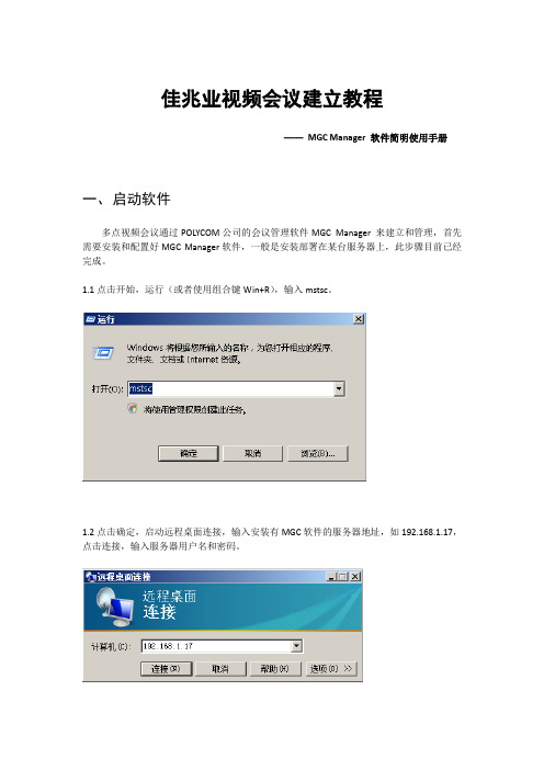
佳兆业视频会议建立教程——MGC Manager 软件简明使用手册一、启动软件多点视频会议通过POLYCOM公司的会议管理软件MGC Manager 来建立和管理,首先需要安装和配置好MGC Manager软件,一般是安装部署在某台服务器上,此步骤目前已经完成。
1.1点击开始,运行(或者使用组合键Win+R),输入mstsc。
1.2点击确定,启动远程桌面连接,输入安装有MGC软件的服务器地址,如192.168.1.17,点击连接,输入服务器用户名和密码。
1.3在服务器桌面上找到MGC manager软件的快捷方式,双击运行。
弹出软件界面。
二、配置会议左侧是当前已经建立的MCU网络,正对某个MCU网络可以对其下的会场建立多点视频会议,下面介绍一般性的多点会议配置过程2.1当前本公司的MCU网络JZY 为脱机:2.2双击,使其联机(或者右键,点击菜单第一个选项connect):2.3点击JZY前面的图标,展开JZY网络2.4选中第二项,“On Going Conferences”2.5点击右键,选择菜单的第一项,New Conference…,新建一个会议。
2.6点击New Conference…,弹出建立一个新会议的配置界面。
其中总共有5个标签页,建立新会议需要用到其中的前四个。
2.7建立步骤2.7.1General标签页这个界面填写会议的基本信息,需填写两个信息,会议名称和会议持续时间,会议名称任意,持续时间根据会议要求设置,一般设置长一点。
2.7.2Settings 标签页在这里进行链路传输配置,需要修改三项内容,从上到下顺次修改。
2.7.3Participants 标签页在这个标签下进行会场的添加和移除。
首先在左侧的全部会场中选择需要开会的会场(多个会场可以单个添加,也可以按住Ctrl键,选择所有会场后一起添加),点击中部的添加会场按钮,则这些会场会进入右部的本次会议会场框。
会议建立前和会议进行中都可以在这个界面进行会场的实时添加和移除。
MCU使用手册

第 7 页 ,共 46 页
7
点击 Disconnect ,出现对话框如下。
文件编号: longhu-003
点击确定按钮 ,与 MCU 的连接即可断开。 关于自动登陆
如果你需要频繁地登陆到 MCU,每次输入密码都是非常麻烦的事情,你可以通过创建 一个登陆记录来自动登陆到 MCU。 注:此设置仅针对不存在系统安全问题并希望简化操作步骤时使用 创建登陆记录
定义如下参数
第 9 页 ,共 46 页
9
文件编号: longhu-003
参数
描述
MCU Date Parameters 这些参数显示 MCU 当前定义的年,月,日。这些参数同样允
Month/Year
许你通过下拉菜单来做新的设置。
Operator Local Time and 显示 MGC Manager 上设置的日期和时间(这个时间来源于
Get Oper Time & GMT 根据 MGC Manager 自动更新 MCU 的时区,日期与时间
Get Oper Time Offset 根据 MGC Manager 的时间自动更新 MCU 的时间(没有时差)
六.定义各项服务
进入 MCU ConfigurationNetwork Services 界面,如下图:
第五章 问题诊断.........................................................................................................................39 一、常见问题解答.................................................................................................................39 二、故障诊断分析.................................................................................................................42
MGC R5 产品说明书

MGC® R5Typical applicationsThe MGC R5 product is a fully inertial navigation system (INS). It can output heading, roll, pitch, heave andposition. Acceleration and velocity of linear motions, as well as angular rates, are output from the unit. The MGC R5 product outputs both processed and raw (gyro and accelerometer) sensor data.The MGC R5 can be used as a stand-alone unit or as an IMU in other systems. The product is designed for high precision maritime applications such as offshore operations and seabed mapping.The product includes integrated navigation algorithms with input from a GNSS receiver for output of aided position and heading data. The proven PFreeHeave® algorithms are part of the navigation algorithms that enable down to 2 cm accuracy in delayed heave output and 3 cm accuracy in real-time heave output. The linear position and velocity measurements can be output in up to four different points on the vessel.FunctionThe MGC can operate in Gyrocompass mode andIntegrated Navigation mode. In the Gyrocompass mode only, input of speed is required. In this mode the product will output heading, roll, pitch and heave accurately. In the Integrated Navigation mode, input of speed, position and PPS from a GNSS receiver is required (VTG, GGA, ZDA). In this mode the product will output heading, roll, pitch, heave and position. In free inertial mode (GNSS denied environment) the position drift is lessthan 20 meters DRMS for a period of 15 minutes (proven performance). The unit is delivered with Windows based configuration and data presentation software, the MRC+. In this software vector arms from where the MGC is mounted to the center of gravity (CG) and two individually configurable monitoring points (MPs) can be defined. The heave measurements can be output in four different locations (the MGC itself, CG, MP1 and MP2) simultaneously on serial lines or Ethernet ports. A typical measurement point is the echo sounder transducer head.Variables outputThe MGC outputs heading, roll and pitch andcorresponding angular rate vectors. The unit outputs relative (dynamic) heave position, velocity andacceleration. In the Integrated Navigation mode it also outputs position in north and east direction in addition to height above the ellipsoid.Digital I/O protocolsMGC data is available through both Ethernet interface and serial lines enabling easy distribution of data to multiple users on board the vessel. Output protocols for commonly used survey equipment are available on two individually configurable serial lines and Ethernet/UDP.GYRO COMPASS AND INSA new family of products with motion sensing and gyro compass functionality is introduced. This MGC R5 product, with emphasis on position drift, includes three Ring Laser Gyros and three linear accelerometers.ORIENTATION OUTPUTAngular orientation range ±180°Resolution in all axes 0.0001°Roll, pitch accuracy (unaided) 0.008° RMSAttitude noise <0.0003° RMSHeading accuracy (speed aided) 0.02° RMS t Heading accuracy (GNSS aided) 0.008° RMS t. Heading settling time to dataavailable <5 min from start-up Heading settling time tofull accuracy (typical) 8 min from start-up GYRO OUTPUTAngular rate range ±125°/s ACCELERATION OUTPUTAcceleration range (all axes) ±45 m/s2HEAVE OUTPUTOutput range ±50 m, adjustable Periods (real-time) 0 to 30 sPeriods (delayed) 0 to 50 sHeave accuracy (real-time) 3 cm or 3% whichever ishighestHeave accuracy (delayed) 2 cm or 2% whichever ishighestPOSITION OUTPUTFree inertial drift (GNSS aided) 0.25 nm/h DRMSFree inertial drift (GNSS aided) <20 m/15 minutes DRMS ELECTRICALVoltage input 24 V DC nominal (18 to32VDC)Power consumption Max 12 W (typical11W)Serial ports:Com1BidirectionalRS-422Com2BidirectionalRS-232Com3 & Com4 Input only, userconfigurableRS-232, RS-422Ethernet output ports 5Ethernet UPD/IP 10/100 MbpsData output rate (max) 200 HzTiming<1msINPUT FORMATSNMEA 0183, incl. GGA, VBW, VTG, ZDA or MRU Normal format OUTPUT FORMATS- MRU normal - Sounder- NMEA 0183 proprietary - EM3000- Atlas Fansweep - TSS1- Seapath binary 23, 25, 26 - PFreeHeave®- KM binary - MDL Trim Cube- RDI ADCP - Tokimec PTVG- NMEA GGA, GLL, HDT, THS, ROT, VTG, GST, VER, HCROTHER DATAMTBF (computed) 50000 hMTBF (Service history based) 100000 hMaterialAnodisedaluminium Connector (MIL. spec.) Souriau 851-36RG 16-26S50WEIGHTS AND DIMENSIONSWeight8.0kgDimensions (HxLxW) 188.9 x 189.5 x189.5mm ENVIRONMENTAL SPECIFICATIONSOperational temperature range -15 °C to +55 °CStorage temperature range -25 °C to +70 °CVibrationIEC60945/EN60945 Enclosure protection IP66Specifications subject to change without any further notice.KONGSBERG SEATEXSwitchboard: +47 73 54 55 00Global support 24/7: +47 33 03 24 07E-mailsales:****************************.comE-mailsupport:******************************* /maritime D e c e m b e r 2 0 2 0。
797中文操作手册_ver5[1].0_
![797中文操作手册_ver5[1].0_](https://img.taocdn.com/s3/m/ff5d72a1b0717fd5360cdca1.png)
N I T O N 重金属元素分析仪X L t 797简易操作手册(塑料&合金模式)罗肯仕科技股份有限公司e R o H S T e c h n o l o g y C o .,L t d1. 开机: 按开关键约5秒,当按开关键或屏幕进入两侧灯亮,就放开4. 版权画面,按Yes进入安全保护密码画面,按屏幕输入密码1234,再按E 进入6. 主功能画面二、自动校正注意:工具及校正画面,按此进入校1. 按此进入工具及校正画面 2.正画面3. 自动校正画面,按此开始自自动校正中动校正6. 主功能画面5. 自动校正完成,按右键回主功能画面至此完成开机自动校正,可开始测试按”Bulk Sample Mode”进入1. 按”Mode”进入测试模式 2.塑料模式(ppm)按”Start”进行分析作业。
3. 按此进入测试分析模式 4.5. 分析仪检测时画面6. 按”Stop”即停止检测;完成检测程序完成后按”Return”或右键回到主功能画面8. 如需输入测试样品各项数据时,按Date Entry进入字段编码画面如有识别条形码,可按1依序(1-5)进行条形码扫瞄。
如无条形码,则按2依序键盘画面进入画面输入编号10. 按触控屏幕或计算机键盘输入编号。
数据编号完成,按Return回数据输入画面11. 按此” Batch”设定检测次数及秒数画面1212. 输入样品需检测次数(连续及时间(Sec),按ok键即可四、A l l o y合金模式测1. 按”Mode”进入测试模式选择2. 按“Alloy”进入合金模式(%)画面3. 按此进入合金判定及成份分析模式按”All Alloys”进入全合金自动测试画面5. 按”Start”进行分析作业(如需输入编号等数据,方式同PVC模式里步骤)6. 全合金自动测试检测时画面7. 测试完成后自动停止检测 8.按”Return”或右键回到主功能画面五、仪器示意图电池式意图开启NITON NDT 软件选取下载钮选取Query Reading 钮存放路径勾选资料选取要下载的数据,选择存放路径及设定文件名选取Download 钮下载数据选择 Done 钮完成下载工作NDT资料表Excel资料表八、检视测试资料I. 开启NITON NDT数据文件II. 点选 View Æ Customize Report 即出现以下对话框III. 勾选欲保留之字段或元素(本例为勾选 Index,Reading No,Time,Duration,Type,Unit,Cd,Pb,Br,Hg,Cr) ,并点选OK即可IV. 最后显示如以下画面III. 勾选Always load hidden readings 及Display ” < LOD ” 方块,Language则勾选Other。
马克五中文使用说明书
本设备经过测试,根据联邦通讯委员会(FCC)规章第 15 部分的有关规定,证明符合 B 级数字设备条件。这些条 件的设立,是为了提供住宅安装设施合理的保护,防止其受到有害的干扰。本设备会产生、使用和放射射频能 量,如果不根据使用说明进行安装和使用,可能会对无线电通信形成有害的干扰。本公司无法保证在某一特定安 装过程中不会出现干扰。用户可以将设备关闭再打开,以测试是否对无线电或电视接收形成有害的干扰,如果有 干扰产生,本公司鼓励用户用以下的一种或多种方法,来试着解决信号干扰问题:
重要注意事项
所有关于 DCI 产品的陈述、技术信息和建议事项,都是根据可靠的资料来源,但是我们并不保证其准确度或完整 性。在使用任何 DCI 产品之前,用户必须确定该产品是否适用。在此所有关于 DCI 产品的陈述都是指由 DCI 递送 的产品,而非指任何未经 DCI 授权,由用户自行改造的产品,亦非指任何第三方的产品。本文中的任何部分都无 法构成 DCI 的售后保证,也不可据此对 DCI 所有产品现有的有限售后保证条件进行修改。
接收器的屏幕菜单功能 .......................................................................8 超声波 ..................................................................................8 数据记录 ................................................................................9 电源 ....................................................................................9 频率 ...................................................................................10 遥感信号 ...............................................................................10 背景灯 .................................................................................11 单点校准 ...............................................................................11 双点校准 ...............................................................................15 自检 ...................................................................................16 深度单位 ...............................................................................16 倾角单位 ...............................................................................17 运行计时器 .............................................................................17
犀牛中文教程:Rhinoceros 3D 参考手册 Rhinoceros NURBS modeling forWindows

RHINO参 考 手 册
Rhinoceros
第
4 页 , 共 733 页
使 下 一 個 觀 視 視 窗 成 為 最 上 層 觀 視 視 窗 (NextViewportToTop) ................................ ......41 關 閉 觀 視 視 窗 (CloseViewport) ................................ ................................ ..................... 42 放 大 觀 視 視 窗 (MaxViewport) ................................ ................................ ........................ 42 複 製 窗 至 所 有 的 觀 視 視 窗 (CopyViewToAll) ................................ ................................ ...42 設 定 最 大 觀 視 視 窗 (SetMaximizedViewport) ................................ ................................ .42 複 製 顯 示 視 窗 至 剪 貼 簿 (CopyDisplayWindowToClipboard)................................ .........43 選 取 色 彩 對 話 窗 (Select Color dialog box) ................................ ................................ ...43 顯 示 指 令 歷 史 (Command history display) ................................ ................................ ...44 指 令 歷 史 (CommandHistory)................................ ................................ ........................ 44 貼 上 指 令 (CommandPaste) ................................ ................................ .......................... 44 讀 入 指 令 檔 (ReadCommandFile) ................................ ................................ ................. 45 第 3章 檔 案 功 能 表 ................................ ................................ ................................ ............. 47
MPLAB Code Configurator v5.1.1 1 用户指南说明书
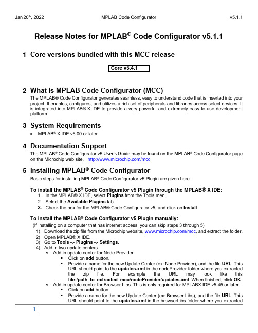
Release Notes for MPLAB® Code Configurator v5.1.11 Core versions bundled with this MCC release2 What is MPLAB Code Configurator (MCC)The MPLAB®Code Configurator generates seamless, easy to understand code that is inserted into your project. It enables, configures, and utilizes a rich set of peripherals and libraries across select devices. It is integrated into MPLAB®X IDE to provide a very powerful and extremely easy to use development platform.3 System Requirements•MPLAB® X IDE v6.00 or later4 Documentation SupportThe MPLAB® Code Configurator v5 User’s Guide may be found on the MPLAB® Code Configurator page on the Microchip web site. /mcc5 Installing MPLAB® Code ConfiguratorBasic steps for installing MPLAB® Code Configurator v5 Plugin are given here.To install the MPLAB® Code Configurator v5 Plugin through the MPLAB® X IDE:1. In the MPLAB® X IDE, select Plugins from the Tools menu2. Select the Available Plugins tab3. Check the box for the MPLAB® Code Configurator v5, and click on InstallTo install the MPLAB® Code Configurator v5 Plugin manually:(If installing on a computer that has internet access, you can skip steps 3 through 5)1) Download the zip file from the Microchip website, /mcc, and extract the folder.2) Open MPLAB® X IDE.3) Go to Tools -> Plugins -> Settings.4) Add in two update centerso Add in update center for Node Provider.▪Click on add button.▪Provide a name for the new Update Center (ex: Node Provider), and the file URL. This URL should point to the updates.xml in the nodeProvider folder where you extractedthe zip file. For example the URL may look like thisfile:/path_to_extracted_mcc/nodeProvider/updates.xml. When finished, click OK.o Add in update center for Browser Libs. This is only required for MPLABX IDE v5.45 or later.▪Click on add button.▪Provide a name for the new Update Center (ex: Browser Libs), and the file URL. This URL should point to the updates.xml in the browserLibs folder where you extractedthe zip file. For example the URL may look like thisfile:/path_to_extracted_mcc/browserLibs/updates.xml. When finished, click OK.5) Uncheck the Microchip Plugins in the Update Center.6) Go to Tools -> Plugins -> Downloaded and click on the Add Plugins... button.7) Navigate to the folder where you extracted the zip file and select the MCC plugin file, com-microchip-mcc.nbm.8) Click on the Install button. MPLAB X IDE will ask to be restarted. Upon restart, the pluginis installed.9) If you unchecked the Microchip Plugins in the Update Center, go back and recheck theselection.6 What’s New7 Repairs and EnhancementsThis section lists the repairs and enhancements for the plugin and core. For library specific issues, please look at the individual library release notes.8 Known IssuesThis section lists the known issues for the plugin, for library specific issues please look at the individual library release notes.8.1 Workarounds8.2 Open9 Frequently Asked QuestionsFor frequently asked questions, please refer to the FAQ post on the MCC Forum.10 S upported FamiliesFor the list of supported families, refer to the release notes of respective libraries.This version of MCC is distributed with the core versions specified in the table shown in Chapter 1 of this document. The following libraries are also distributed with core compatibility as shown in the table below:Additional and archived libraries can be found at: /mcc.11 C ustomer Support11.1 MCC SupportTechnical support is available through the website at: /support11.2 The Microchip Web SiteMicrochip provides online support via our web site at . This web site is used asa means to make files and information easily available to customers. Accessible by using your favoriteInternet browser, the web site contains the following information:•Product Support–Data sheets and errata, application notes and sample programs, design resources, user’s guides and hardware support documents, latest software releases and archived software•General Technical Support–Frequently Asked Questions (FAQs), technical support requests, online discussion groups/forums (), Microchip consultant program member listing•Business of Microchip–Product selector and ordering guides, latest Microchip press releases, listing of seminars and events, listings of Microchip sales offices, distributors and factory representatives.11.3 Additional SupportUsers of Microchip products can receive assistance through several channels:•Distributor or Representative•Local Sales Office•Field Application Engineering (FAE)•Technical SupportCustomers should contact their distributor, representative or field application engineer (FAE) for support.Local sales offices are also available to help customers. A listing of sales offices and locations is available on our web site.Generic technical support is available through the web site at: .12 A ppendix: Supported DevicesFor the list of supported devices, please refer to the release notes of respective libraries.。
MGC操作手册-Ver5

MGC操作手册-Ver5MGC操作手册-Ver5 (1)第一章MGC硬件结构描述 (2)一. MGC的外形图 (2)二. 硬件特点 (2)三. 前面板 (2)四. 后面板 (3)五.俯视图 (4)六. 内部结构图 (4)七.模块介绍 (5)第二章开会前的准备工作 (8)一.正确连接MCU 至网络 (8)二.定义及修改MCU的控制IP地址 (8)三.安装MGC Manager (9)四.连接MGC (11)五.修改MGC的时间 (14)六.定义各项服务 (16)第三章召开会议 (22)一. 连接MCU (22)二. 迅速召开一个即时会议 (22)第四章监控会议 (33)一、一般监控 (33)二、监控中对与会者的操作 (36)三、监控中对会议的操作 (40)第一章MGC硬件结构描述一. MGC的外形图如下为MGC100的外形图,MGC50与此外形相似,仅槽位数目不同二. 硬件特点●支持在线的设备硬件诊断.●所有的模块均为前触式插拔方式, 易于维护.●所有的功能模块支持热插拔.●设备可以自动地辨认功能模块. 同时, 可获知其能力.●可以支持在线的软件升级.●指示灯可以指示模块目前的运行状态.三. 前面板●MGC100为16个通用插槽,MGC50为8个通用插槽●MGC100为三组共享负载电源模块四. 后面板●电源支持220交流或-48V直流●支持24小时开机.五.俯视图六. 内部结构图●AUDIO 模块●AUDIO+模块(包括,AUDIO+8,AUDIO+12/24,AUDIO+24/48,AUDIO+48/96)●VIDEO 模块●VIDEO+ 模块●ISDN/E1 模块●ATM 模块●H323 模块●IP24模块●IP48模块●V35/RS449 模块●MUX 模块●DATA 模块●主控制模块●电源模块七.模块介绍接口板●Polycom的MCU支持专线接入, 同时支持ISDN接入.●对于ISDN网络, MCU提供 PRI(30B+D).●对于专线网络, MCU提供E1接口.●NET模块可以分为NET-2/4/8.●接口类型为, BNC或RJ48.2.ATM模块155M的多模光接口, OC-3.3.H323 模块、IP24模块与IP48模块●H323模块支持12个384K的IP点.6个768KIP点●IP24模块支持24个384K的IP点,12个768KIP点,48个128K点●IP 48模块支持48个384K的IP点,24个768KIP点,48个128K点●IP端口为10M/100M自适应, 可设置为自动, 全双工或半双工.4、关于Dongle模块的说明:此模块用于POL YCOM MCU新版软件(MGC 5.02版及以上版本)的知识产权保护功能,安装在MGC MCU背板串口上。
- 1、下载文档前请自行甄别文档内容的完整性,平台不提供额外的编辑、内容补充、找答案等附加服务。
- 2、"仅部分预览"的文档,不可在线预览部分如存在完整性等问题,可反馈申请退款(可完整预览的文档不适用该条件!)。
- 3、如文档侵犯您的权益,请联系客服反馈,我们会尽快为您处理(人工客服工作时间:9:00-18:30)。
MGC操作手册-Ver5MGC操作手册-Ver5 (1)第一章MGC硬件结构描述 (2)一. MGC的外形图 (2)二. 硬件特点 (2)三. 前面板 (2)四. 后面板 (3)五.俯视图 (4)六. 内部结构图 (4)七.模块介绍 (5)第二章开会前的准备工作 (8)一.正确连接MCU 至网络 (8)二.定义及修改MCU的控制IP地址 (8)三.安装MGC Manager (9)四.连接MGC (11)五.修改MGC的时间 (14)六.定义各项服务 (16)第三章召开会议 (22)一. 连接MCU (22)二. 迅速召开一个即时会议 (22)第四章监控会议 (33)一、一般监控 (33)二、监控中对与会者的操作 (36)三、监控中对会议的操作 (40)第一章MGC硬件结构描述一. MGC的外形图如下为MGC100的外形图,MGC50与此外形相似,仅槽位数目不同二. 硬件特点●支持在线的设备硬件诊断.●所有的模块均为前触式插拔方式, 易于维护.●所有的功能模块支持热插拔.●设备可以自动地辨认功能模块. 同时, 可获知其能力.●可以支持在线的软件升级.●指示灯可以指示模块目前的运行状态.三. 前面板●MGC100为16个通用插槽,MGC50为8个通用插槽●MGC100为三组共享负载电源模块四. 后面板●电源支持220交流或-48V直流●支持24小时开机.五.俯视图六. 内部结构图●AUDIO 模块●AUDIO+模块(包括,AUDIO+8,AUDIO+12/24,AUDIO+24/48,AUDIO+48/96)●VIDEO 模块●VIDEO+ 模块●ISDN/E1 模块●ATM 模块●H323 模块●IP24模块●IP48模块●V35/RS449 模块●MUX 模块●DATA 模块●主控制模块●电源模块七.模块介绍接口板●Polycom的MCU支持专线接入, 同时支持ISDN接入.●对于ISDN网络, MCU提供 PRI(30B+D).●对于专线网络, MCU提供E1接口.●NET模块可以分为NET-2/4/8.●接口类型为, BNC或RJ48.2.ATM模块155M的多模光接口, OC-3.3.H323 模块、IP24模块与IP48模块●H323模块支持12个384K的IP点.6个768KIP点●IP24模块支持24个384K的IP点,12个768KIP点,48个128K点●IP 48模块支持48个384K的IP点,24个768KIP点,48个128K点●IP端口为10M/100M自适应, 可设置为自动, 全双工或半双工.4、关于Dongle模块的说明:此模块用于POL YCOM MCU新版软件(MGC 5.02版及以上版本)的知识产权保护功能,安装在MGC MCU背板串口上。
MCU新版软件在系统开机后,会自动检查Dongle模块及其中的许可证号码的匹配情况:若匹配,则在MGR管理软件的界面上,可以查看与操作MCU上所配置的各种功能模块;若不匹配,在MGR管理软件的界面上,用户无法看到MCU上所配置的各种功能模块的情况,因而无法进一步执行相关的操作。
Dongle模块的安装图示:`第二章开会前的准备工作一.正确连接MCU 至网络●将MCU安装到相应的机架上,按照电源类型(直流或交流)接好电源。
●用网线将MCU的控制端口以及所有MG323板卡连接至网络。
建议:a)MCU的电源应接有UPS电源保护,并设置有地线b)除MCU的控制端口外,其余MG323板卡所接的交换机上相应端口都设置为100M全双工模式。
二.定义及修改MCU的控制IP地址●鼠标右键点击MCU图标,会出现如下菜单●点击IP Configuration,菜单将会显示如下●定义如下参数●点击O K完成,配置将在重新启动MCU后生效。
三.安装MGC Manager1.放入光盘到光盘驱动器中,运行setup,安装程序向导会出现版权事项,点击“Next”,出现如下界面:2.点击Next,会出现如下界面:3.在相应位置输入“用户名”以及公司的名称,点击Next,显示如下界面:4.选择要安装MGC Manager软件的路径,如果接受默认目录,点击Next。
如要更改目录,点击Browse,选择要安装的目录,点击Next显示如下界面:5.选择要安装MGC Manager图标的程序目录,如接受默认设置,点击Next,检查所有安装信息是否正确。
如要更改设置,点击Back直到出现相应的屏幕。
点击Next 后开始拷贝文件到你的硬盘中。
当安装程序完成后,会显示如下界面:6.点击Finish。
MGC Manager现在已经安装到你的计算机中。
四.连接MGCMGC Manager的启动进入WINDOWS的开始→程序→MGC Manager V5.0→MGC Manager V5.0,点击鼠标左键,启动MGC Manager。
出现MGC Manager操作系统的主窗口。
连接到MCU●双击MCUs Network图标,在MCUs Network图标下将出现MCU的列表。
如果为首次安装,需要建立一个新的连接。
用鼠标右键点击MCUs Network,点击New MCU,输入相应的名称和MCU的控制端口IP地址。
●右键点击MCU列表中需要使用的MCU的名称。
●点击Connect就可以连接到MCU上。
●输入登陆名和密码,然后点击OK。
MCU出厂默认的用户名称和密码均为ACCORD或POL YCOM(均为大写)建议:安装时更改用户名与密码,以提高系统安全性●连通MCU以后,显示如下界面。
●用右键点击MCU的名字●点击Disconnect ,出现对话框如下。
●点击确定按钮,与MCU的连接即可断开。
关于自动登陆如果你需要频繁地登陆到MCU,每次输入密码都是非常麻烦的事情,你可以通过创建一个登陆记录来自动登陆到MCU。
注:此设置仅针对不存在系统安全问题并希望简化操作步骤时使用创建登陆记录●在主菜单上选择File→Preferences ,出现子菜单如下:●点击Create Login Record, 出现对话框如下:●输入登陆的用户名和密码。
●点击OK。
以后如再次连接,便可以直接进入MCU而不需要输入用户名和密码。
删除登陆记录●在主菜单上选择File→Preferences ,出现子菜单。
●选择Clear Login Record,登陆记录就被删除了。
五.修改MGC的时间●用鼠标右键点击MCU的图标,弹出如下菜单。
●点击MCU Time.打开MCU GMT时间的对话框如下:定义如下参数MCU Date Parameters Month/Year这些参数显示MCU 当前定义的年,月,日。
这些参数同样允许你通过下拉菜单来做新的设置。
Operator Local Time and Date 显示MGC Manager 上设置的日期和时间(这个时间来源于Windows 操作系统) Operator GMT Offset与MGC Manager 的时差(这个时间来源于Windows 操作系统)MCU Local Time 显示MCU 当前设置的时间。
如要手工修改这个参数,点击小时或分钟部分以修改 MCU GMT Offset 显示MCU 当前的时差Get Oper Time & GMT 点击此键根据MGC Manager 自动更新MCU 的时区,日期与时间 Get Oper Time Offset点击此浆根据MGC Manager 的时间自动更新MCU的时间(没有时差)六.定义各项服务进入 MCU Configuration →Network Services 界面,如下图:一、定义H.323服务● 用鼠标右键点击 H.323,选择 New H.323 Service ,弹出菜单如下:●定义如下参数:点击●如果打开Quality Of Service的设置,则会出现如下页面,否则直接跳到下一步定义如下参数如果需要设置Gatekeeper选项,需要在上一步选中External Gatekeeper选项,这样会进入如下页面,否则直接跳到下一步设置如下参数:点击Next 进入到下一页面1.点击图标,进入下一级菜单定义如下参数*如需要将音频/视频数据业务通过防火墙,则需要修改如下设置:首先要选中Enable Fixed Ports,然后设置相应端口号码。
点击OK ,点击Finish,完成H.323 板的配置。
配置H323网络接口板●用鼠标双击MCU Configuration●选择MG323板,点击鼠标右键,选择Properties,弹出如下菜单。
●点击其中的H323-Network Parameters●点击 Null Configuration ,并在Circuit ID 的输入框内输入在H323服务NetworkService中Span 里确定的Circuit ID 值,比如24。
然后点击 OK如有多块MG323板卡,重复以上操作即可第三章召开会议一. 连接MCU启动并连接MGC Manager,如图用鼠标右键点击MCU,选择“Connect…”,然后在“Logon”窗口键入用户名和密码。
缺省用户名和密码均为大写的“ACCORD”或者“POL YCOM”,选择“OK”完成连接。
二. 迅速召开一个即时会议1.开MCU,右键点击“On Going Conferences”,选择“New Conference…”;2.出现如下窗口后,在“Name”栏中键入会议名称,在“Password”中输入需要设置的会议密码,在“Duration”栏中键入会议共召开多长时间,注意会议时间最长为99小时,缺省值为2小时,然后选择所需要召开的会议相关类型在Video Session栏中选择符合自己需求的会议模式。
Video Switching表示所有与会者连接的速率都是一样的;Transcoding表示允许与会者连接会议的速率不一样;Continuous Presence表示不但允许与会者连接会议的速率不一样,而且该会议还带分屏方式;Software CP为软件分屏的功能,不需要硬件Video板卡,但受相应H323板卡数目限制,此功能仅在纯IP(H323)网络下使用。
在Conference Type中的Standard为默认会议属性Meeting Room为聊天室会议,会议中不需要定义参加会场,分会场直接拨叫会议名称即可*此功能需要Gatekeeper支持Operator用于Greet & Guide(迎接与引导)功能。
*此功能为选项Meet Me Per Conference功能在Gatekeeper支持情况下,可实现定义部分会场与部分会场直接拨叫会议名称两种方式共用Remarks栏可以对会议做标记,例如标记会议由哪个部门召开,重要性等。