MiniKit用户手册用户手册用户手册用户手册
MiniTech+ 个人辅助交流器 说明书

MiniTech+TM个人辅助交流器(增音器)用户手册一:配件说明二:操作指南1.佩戴方法2.开/关机功能3.音量控制4.音调控制5.更换电池三:日常维护四:简单故障处理五:数据线组合(可以选择性购买)六:技术参数七:维修八:免责声明一.配件说明:1.电源开关2.麦克风3.音量按钮4.音调旋钮5.耳机6.皮带夹7.电池仓8.皮套9.电源指示灯23194 58671二.操作指南:1.佩戴方法a.首先把MiniTech+按图指示装入皮套内,以此来保护机器。
b.在开机之前, 请务必将麦克风和耳机完全插入麦克风和耳机的指标孔内, 否则高频率的音量会损伤您的听力. (附: 任何标准插头的耳机都可以与本机器连接使用)c.随机附带的标准耳机适合大多数用户的耳道。
耳塞与耳道的紧密吻合对于使用本产品非常重要,否则会降低本产品的使用效果。
佩戴时将耳机轻轻地贴入耳道,耳机的出声孔与耳道口保持一致,以便于声音顺利地由耳道传入耳内。
使用皮带夹,您可以很好地将本机器固定在您的皮带上。
d.摘下助听器在摘下MiniTech+之前,建议您先将电源关闭,然后用手轻轻地摘下耳机。
麦克风可以摘下,放入皮套内的麦克风套里。
22.开/关机功能a.将电源开关推向“ON”的位置,电源接通,电源指示灯为绿色,机器可以开始工作;b.将电源开关推向“OFF”的位置,电源断开,电源指示灯熄灭,机器停止工作。
c.如果在使用过程中或者开机后电源指示灯为红色,那表示电池电力不足,建议您在8小时内更换电池。
如果开机后,电源指示灯没有亮起,一般情况下表明电池完全消耗完毕,请更换新的电池。
3.音量控制 在MiniTech+的表面有两个橘黄色的按钮,+为加音量,-为减音量。
根据自己的需要,用手请轻轻地按下按钮,手动调节音量的大小。
每当使用完毕关闭电源后,音量将自动回归到原始状态;下次使用前请您再重新调节适合您的音量。
34.音调旋钮 在MiniTech+的右侧有一个调节音调的旋钮,您可以根据自己的需要,用手指轻轻地旋转音调旋钮,手动调节音调的高低。
Akai MPK Mini Play编辑器用户指南说明书

Table of ContentsUser Guide (4)Introduction (4)Support (4)Installation (4)Windows (4)macOS (4)Setup (5)Features (6)Graphical Interface (6)Operation (8)Managing Your Favorites (8)Saving Favorites (8)Loading Favorites (8)Sending Favorites (9)Editing a Pad’s MIDI Note (10)Editing a Knob (10)Editing the X-Y Controller (Joystick) (11)2Editing the Keyboard and Arpeggiator (12)Keyboard (12)Arpeggiator (13)Editing the Sound (14)Appendix (15)Trademarks and Licenses (15)3The MPK Mini Play Editor software gives you intuitive ways to edit the many functions that your MPK Mini Play can perform.SupportFor the latest information about this product (system requirements, compatibility information, etc.) and product registration, visit .For additional product support, visit /support.Windows1.Double-click the .exe installer file you downloaded.2.Follow the on-screen instructions.macOS1.Double-click the .dmg installer file you downloaded.2.Follow the on-screen instructions.45To use the MPK Mini Play Editor: 1.Optional: Connect M PK M ini Play to your computer using a standard USB cable. (If you are connecting MPK Mini Play to a USB hub, make sure it is a powered hub). You can still use the Editor and create favorites without connecting an MPK M ini Play, but you will not be able to send/load favorites to/from it.2.Open the M PK M ini Play Editor on your computer. The window will show a visual representation of all your M PK M ini Play’s editable controls. See Features > Graphical Interfacefor an overview of each section.6Graphical InterfaceThe MPK Mini Play Editor has a straightforward user interface that can be broken down into seven sections for editing:1.Joystick: These settings control the parameters affected when moving the X-Y Controller alongits X axis (left/right) or Y axis (up/down). See Operation > Editing the X-Y Controller (Joystick) to learn more.2.Sound: These two fields determine the overall sound of the keyboard as well as the pads. SeeOperation > Editing the Sound to learn more.3.Pads: This section enables you to edit note assignments for the pads. 16 pads are pictured inthe Editor: 8 of them correspond to the pads on the MPK Mini Play when Bank A is active, and the other 8 correspond to the pads on the M PK M ini Play when Bank B is active. See Operation > Editing a Pad’s MIDI Note to learn more.4.Knobs: This section enables you to edit the function of the knobs. 8 knobs are pictured in theEditor: 4 of them correspond to the knobs on the MPK Mini Play when Bank A is active, and the other 4 correspond to the knobs on the MPK Mini Play when Bank B is active. See Operation > Editing a Knob to learn more.5.Favorites: These controls let you import a favorite from your computer or from your connectedMPK Mini Play. They also allow you to save the current settings as a favorite and export them to your computer or to your connected M PK M ini Play. See Operation > Managing Your Favorites to learn more.6.Channels: These two fields determine the channels through which the pads, knobs, X-YController, and keyboard send MIDI data. Specific instructions are provided in the chapters for each control: Operation > Editing a Pad’s MIDI Note, Editing a Knob, Editing the X-Y Controller (Joystick), Editing the Keyboard and Apeggiator > Keyboard.7.Keyboard and Arpeggiator: This is a visual representation of the 25-key keyboard as well asthe settings that control the timing, range, and general behavior of the arpeggiator. See Operation > Editing the Keyboard and Arpeggiator to learn more.78Managing Your FavoritesWith the Favorites feature, you can save all your current settings in the Editor to a single .mpkplay file that can be loaded onto your MPK Mini Play. MPK Mini Play holds a maximum of eight favorites, but you can store more favorites on your computer to load onto MPK Mini Play later with the Editor. This way, you can have countless different control configurations for different situations. For instance, you may use different favorites with different software. Or you may use some favorites for production and others for performance.Saving FavoritesAfter saving a favorite on your computer, you can send it to MPK Mini Play or edit it again later. All settings that you see in the Editor software will be saved in the favorite.To save a favorite: Go to File > Save Favorite . Alternatively, you can type Ctrl + S (Windows) or + S (Mac). Then select the destination folder on your computer, enter a file name, and click Save . The favorite will be saved as an .mpkplay file.Loading FavoritesTo load a favorite from a connected MPK Mini Play: Click the R (receive) icon corresponding to the number of the desired favorite on your MPK Mini Play (1-8). Note : Using the software to edit a favorite loaded from your MPK Mini Play will not automatically affect this favorite on your keyboard; you will have to send the edited favorite to the keyboard after modifying it. See Sending Favorites below to learn more.To load a favorite from your computer, go to File > Open Favorite.Alternatively, you can type Ctrl + O (Windows) or + O (Mac). Then locate the desired .mpkplay file and click Open .Sending FavoritesWhen you send from the Editor to a connected MPK Mini Play, all settings that you see in the Editor will be stored as a favorite on the MPK Mini Play’s internal memory. When playing your keyboard, the favorite will be available for you to activate whenever you like.corresponding to the number of the favorite you want to replace on your M PKMini Play (1-8). Doing so will overwrite the favorite currently stored in this numberslot on the MPK Mini Play.You can also send a favorite to M PK M ini Play's RAM, where it will be kepttemporarily and will not overrite any favorite stored on the device. This applies thesettings to the MPK Mini Play and lets you try them out without fully committingto them. If you then decide that you like the settings, you can save the favorite toyour computer (see Saving Favorites above) or overwrite one of the currentlystored favorites on your MPK Mini Play.To send a Program to the RAM of a connected MPK Mini Play, click the SEND TO RAM icon or go to File > Send Favorite > Ram.Note: To avoid losing the settings kept in the RAM, you will need to save them before modifyingthem with the Editor or exiting the Editor.910Editing a Pad’s MIDI NoteYou can set the MIDI note for any of the pads in Bank A or Bank B. You can also set the channel through which all the pads send their MIDI notes.To select a pad’s MIDI note: Click the Note field within the pad and then type the desired M IDI note number (0 – 127). The M IDI note value will change accordingly. The current MIDI note value (C-1 – G9) will be displayed on the pad.To select the MIDI channel for all the pads: Click the Pad MIDI Channel field at the bottom of the window. In the pop-up menu that appears, select the desired MIDI channel number (1 – 16).Editing a KnobYou can edit settings for each of the eight knobs, including CC message, minimum value, maximum value, and FX level. You can also set the channel through which all the knobs send MIDI data.To select the CC message a knob sends: Click the CC field under a knob and then type the desired CC number (0 – 127).To select a knob's minimum and maximum values: Click the Lo field (minimum) or Hi field (maximum) under a knob and then type the desired value (0 – 127).To assign the FX level : Click the effect name field and then type the desired value (0 – 127). Each knob in each bank has its own designated effect.To select the MIDI channel for all the knobs, open the Keybed / Controls MIDI Channel pop-up menu at the bottom of the window. Then select the desired MIDI channel number (1 – 16). This will affect the X-Y Controller and keyboard as well as the knobs.11Editing the X-Y Controller (Joystick)You can designate the function for each axis of the X-Y Controller (joystick), allowing you to use it to manipulate up to two different parameters simultaneously.To designate the function of the axis, click the X Axis or Y Axis field under the X-Y Controller and then select the desired function from the pop-up menu: • Pitchbend: M oving the X-Y controller along the axis will bend thekeyboard pitch.• Single CC: M oving the X-Y controller along this axis will send a CCmessage.• Dual CC: M oving the X-Y controller along this axis will send one CCmessage in the positive direction (up or right) and another CC message in the negative direction (down or left).To select the CC message the X-Y Controller sends (when set to Single CC or Dual CC), click the CC field(s) and then type the desired value (0 – 127).To select the MIDI channel for the X-Y Controller, open the K eybed / Controls MIDI Channel pop-up menu at the bottom of the window. Then select the desired MIDI channel number (1 – 16). This will affectthe knobs and keyboard as well as the X-Y Controller.Editing the Keyboard and ArpeggiatorKeyboardThe Editor allows you to set the keyboard's octave and transposition.To transpose the keyboard, click the Transpose field under the keyboard. When the pop-up menu appears, select the desired value (-12 to 12 semitones). A transposition of 0 means the keyboard is not transposed. For reference, the leftmost key will display its note value to indicate the current transposition.To change the keyboard's octave, click the Octave field under the keyboard. When the pop-up menu appears, select the desired value (-4 to 4 octaves). An octave of 0 means the keyboard is at its center/default octave.To select the MIDI channel for the Keyboard: open Array the Keybed / Controls MIDI Channel pop-up menuat the bottom of the window. Then select the desiredM IDI channel number (1 – 16). This will affect theknobs and X-Y Controller as well as the keyboard.12ArpeggiatorYou can edit various parameters for the arpeggiator.To activate or deactivate the arpeggiator: Click the On/Off icon. The icon’s outline will be red if the arpeggiator is on and gray if the arpeggiator is off.To set the arpeggiator's time division: Click the Time Div field. When the pop-up menu appears, select the desired setting (1/4 – 1/32T).To set the arpeggiator's mode: Click the Mode field. When the pop-up menu appears, select the desired setting from the pop-up menu.The mode determines how the arpeggiated notes are played back:•Up: Notes will sound from lowest to highest.•Down: Notes will sound from highest to lowest.•Exclusive: Notes will sound from lowest to highest and then back down. The lowest and highest notes will sound only once at the directional change.•Inclusive: Notes will sound from lowest to highest and then back down. The lowest and highest notes will sound twice at the directional change.•Order: Notes will sound in the order they were pressed.•Random: Notes will sound in random order.1314To activate or deactivate the Latch: Click the Latch field and then select Off or On from the pop-up menu. • Off: When the Latch is Off and you press keys, the Arpeggiator will cease after you release your fingers from the keyboard.•On: When the Latch is On and you press keys, the Arpeggiator will continue even after you release your fingers from the keyboard. While holding down the keys, you can add more notes to the arpeggio by pressing down additional keys. If you press the keys, release them, and then press a new combination of keys, the Arpeggiator will arpeggiate the new notes.To set the arpeggiator's octave range: Click the Octave field and select the desired value from the pop-up menu: 0, 1, 2, or 3 octaves.To set the arpeggiator's swing, click the Swing field and select the desired setting from the pop-up menu: 50% (no swing), 55%, 57%, 59%, 61%, or 64%.To set the minimum number of taps required for MPK Mini Play’s Tap Tempo button to detect a new arpeggiator tempo: Click the Tempo Taps field and select the desired number from the pop-up menu: 2, 3, or 4 taps.Note: M PK M ini Play's Tap Tempo button is disabled if the Arpeggiator is synced to an external clock.Editing the SoundThe Editor allows you to select the default keyboard sound and pad sound for a favorite.To select the keyboard sound : Click the Keyboard Sound field at the top of the window. When the pop-up menu appears, select one of the 130 available sounds.To select the pad sound : Click the Pad Sound field at the top of the window. When the pop-up menu appears, select one of the 10 available sounds.Akai Professional is a trademark of inMusic Brands, Inc., registered in the U.S. and other countries. macOS is a trademark of Apple Inc., registered in the U.S. and other countries.Windows is a registered trademark of M icrosoft Corporation in the United States and other countries.All other product or company names are trademarks or registered trademarks of their respective owners.15。
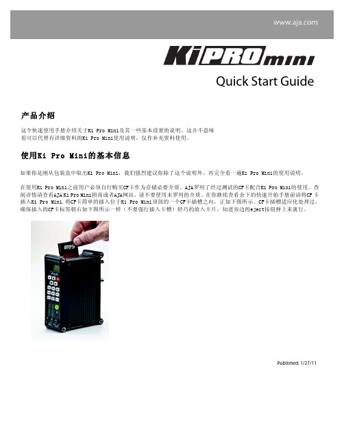
KiPro_Mini_快速使用手册
这个快速使用手册介绍关于Ki Pro Mini及其一些基本设置的说明。
这并不意味着可以代替有详细资料的Ki Pro Mini使用说明,仅作补充资料使用。
使用Ki Pro Mini的基本信息如果你是刚从包装盒中取出Ki Pro Mini,我们强烈建议你除了这个说明外,再完全看一遍Ki Pro Mini的使用说明。
在使用Ki Pro Mini之前用户必须自行购买CF卡作为存储必要介质。
AJA罗列了经过测试的CF卡配合Ki Pro Mini的使用。
查 阅详情请查看AJA Ki Pro Mini指南或者AJA网站。
请不要使用未罗列的介质。
在你继续查看余下的快速开始手册前请将CF 卡 插入Ki Pro Mini.将CF卡简单的插入位于Ki Pro Mini顶部的一个CF卡插槽之内,正如下图所示。
CF卡插槽适应化处理过, 确保插入的CF卡标签朝右如下图所示一样(不要强行插入卡槽)轻巧的放入卡片,知道旁边的eject按钮弹上来就行。
Quick Start Guide产品介绍Published: 1/27/11注意 未能正确安装或卸载CF 卡,或在录制时丢失电源,可能会导致不可恢复的数据丢失意外损失存储介质插入后,将Ki Pro Mini放置在摄像机或者视频源附近通过如下方法:• 将它放置于平稳的平面上比如桌面或者陆架上• 使用Ki Pro Mini的选配件Desk Stand和电池适配器索带使其站立• 使用Ki Pro Mini的选配件Mounting brackets装备在摄像机,三角架,或者其它摄像机配件上Ki Pro Mini如图中显示的通过选配件站立架放置(4个螺钉固定站立架和机体)通过4个螺钉和电线适配器固定站立(底视图)可选的Ki Pro Mini Stand(还有4个螺钉和电线适配器组件) Ki Pro Mini如图中显示的通过选配件站立架放置(4个螺钉固定站立架和机体)通过4个螺钉和电线适配器固定站立(底视图) 可选的Ki Pro Mini Stand(还有4个螺钉和电线适配器组件)Optional stand comes with 4 screws and a power cable adapter (bottom view) 装配相机用的Ki Pro Mini的选配件Bracket套件如图所示可以在任一侧面安装选配套件使音视频接口连接上KiPro Mini摄像机提供SDI接口输出音频和视频,在某些情况下,还通过同一根线连接上Ki ProMini传输时间码。
派诺特Minikit车载声控系统使用流程
派诺特Minikit车载声控系统使用流程Parrot MINIKIT是Bluetooth的免提工具包。
没有必要拿着移动电话机与线另一端的人交谈。
由于配备了嵌入式电池,您可以随处使用,比如在汽车里、在办公式和家里。
由于设备利用了先进的信号处理系统(DSP II)的全面优点,通话完全采用双工模式,同时消除背景噪音、减少回音,增加了听音的质量。
连接您的Bluetooth电话/PDA为保证您电话机上的所有功能都可以使用,必须在Parrot MINIKIT上设置特别的配对模式。
普通配对-适用大多数的电话机(支持免提协议)一旦您的Parrot MINIKIT已经完全充电,必须配对您的Bluetooth电话/PDA。
• 从您的Bluetooth 电话机上搜索Bluetooth外围设备(参考电话使用手册)。
• 选择“MINIKIT”。
• 提示时在您的电话机上输入“1234”。
• 当两台设备连接时Parrot MINIKIT会说“配对成功”。
连接时,该设备会发出“嘟”的声音。
• 如果您的电话机支持该功能,语言会自动选择。
否则,您可以自己调整语言。
选择配对- 使电话支持耳机协议(参考电话使用手册)• 同时按红键和旋转键三秒钟。
LED交替闪烁蓝、红光。
所有Bluetooth 设备可见Parrot MINIKIT三分钟。
• 从您Bluetooth电话机上搜索Bluetooth外围设备(参考电话使用手册)。
• 选择“MINIKIT”。
• 提示时在您的电话机上输入“1234”。
• 当两台设备连接时Parrot MINIKIT会说“配对成功”。
连接时,该设备会发出“嘟”的声音。
• 如果您的电话机支持该功能,语言会自动选择。
否则,您可以自己调整语言。
声音控制记录关键词点击中央键–工具包会说“语言”及工具包目前正在使用的语言名称。
• 转动滚频轮直至工具包说“记录关键词”,然后确认。
• 工具包会说“记录所有的关键词。
”• 如果已经记录一个或多个关键词,工具包会选择还没有记录的第一个关键词。
Minikit+_Plus详细说明书

Parrot Minikit+用户手册內容內容 (2)開始使用 (4)開始使用前 (4)包裝內容 (4)更改语言版本 (4)安装 Parrot MINIKIT+ (4)电池 (5)为 Parrot MINIKIT+ 充电 (5)待机模式 (6)电池容量 (6)使用 (6)开启 / 关闭Parrot MINIKIT+ (6)浏览菜单 (6)连接 (7)与手机建立蓝牙连接 (7)配对手机 (7)自动连接 (8)解决记忆已满的问题 (8)使用 Parrot MINIKIT+ 连接 2 部手机 (8)激活双重模式 (8)连接 2 部手机到Parrot MINIKIT+ (8)主手机和副手机 (8)拨打和接听电话 (8)切换主、副手机位置 (9)同步通讯录 (9)自动同步 (9)关闭自动同步 (10)经蓝牙传输联络人资料 (10)电话 (11)接听电话 (11)铃声 (11)关键词 (11)接听来电 (11)拒绝来电 (11)拨打电话 (12)进行语音拨号 (12)联系有数个电话号码的联络人 (12)联系通讯簿中的联络人 (12)重拨最后拨打的号码 (12)在通话时使用Parrot MINIKIT+ (13)调整音量 (13)将通话转到手机接听 (13)处理通话时另一个来电 (13)管理语音信箱 (13)挂断通话 (13)音乐/导航 (14)音乐 (14)导航指示 (14)调节音量 (14)排解疑难 (15)Parrot MINIKIT+说出 <记忆已满> (15)Parrot MINIKIT+似乎死机了 (15)装置似乎不能与我的手机配合使用 (15)開始 使用开始使用前警告: 在使用所有须提高集中力的功能时,应于车辆停止时才可使用。
您和其它道路使用者的安全比通话 重要。
请负起驾驶者的负任 :小心驾驶,并注意您周围的环境。
如您选择不尊重这个警告,派诺特将不会 对任何后果负责。
包装内容Parrot MINIKIT+遮阳挡固定带USB / 迷你USB 连接线点烟器充电器更改语言版本 Parrot MINIKIT+ 语言版本可经软件更新作更改。
车载蓝牙说明书

使用 ................................................................................................................................. 4
开始使用前.................................................................................................................................................... 4 安装 Parrot MINIKIT+................................................................................................................................ 4
连接 ................................................................................................................................. 7
与手机建立蓝牙连接 .................................................................................................................................... 7 配对手机 ................................................................................................................................................... 7 自动连接 ................................................................................................................................................... 8 解决记忆已满 的问题 .......................................................................................................................... 8
Parrot MINIKIT Smart 用戶手冊

用戶手冊开始使用前 0安装 (4)安装Parrot MINIKIT Smart (4)放置手机 (6)为Parrot MINIKIT Smart充电 (6)为手机充电 (7)开始使用 (8)开启 / 关闭Parrot MINIKIT Smart (8)浏览Parrot MINIKIT Smart菜单 (8)透过蓝牙配对手机 (8)同步电话簿 (9)录制声波纹 (9)电话功能 (10)接听电话 (10)拨打电话 (10)在通话时使用Parrot MINIKIT Smart (11)排解疑难 (13)装置说出 <记忆已满> (13)装置似乎死机了 (13)装置似乎不能与我的手机配合使用 (13)导航指令的音量太低 (13)一般信息 (14)开始使用前∙在使用所有须提高集中力的功能时,应于车辆停止时才可使用。
您和其他道路使用者的安全比通话或 GPS 指示重要。
∙如果您的车辆配有一块有隔热膜的挡风玻璃,您的GPS信号质量可能会下降。
安装安装Parrot MINIKIT Smart∙用合适的清洁产品清洁的准备安装的位置,然后将固定支架安装在挡风玻璃上(图1, 第 4 页)。
要做到这一点,松开锁定杆,将吸盘向挡风玻璃压下,正确固定支架的位置后,再将锁定杆扣紧。
∙如果您想将Parrot MINIKIT Smart 安装在您的仪表板上,须先将圆形底部托架黏固到仪表板。
这样做,您须要将双面贴黏贴在托架的吸盘上。
托架黏贴到仪表板后,等待约2 小时以确保双面贴黏稳在仪表板上。
∙车厢内的冷/ 暖空调有可能会导致吸盘从挡风玻璃分离。
在每次使用Parrot MINIKIT Smart前先确保吸盘已稳固地贴在挡风玻璃上,否则装置有可能在行车时掉下。
如有必要,请重新固定支架。
∙将Parrot MINIKIT Smart安装在固定支架上。
同时按下磁石接口的两边将Parrot MINIKIT Smart 接连到支架上。
mirneasyminikit中文版
miRNeasy Mini kit实验前注意事项:1、这个实验方法是为了从组织(和/ 或)细胞中提取总RNA,包括小分子 RNA。
2、有必要的话,可以加热使Buffer RWT中的积淀溶解。
3、除了步骤 5 中的液相分别,其他操作均应该在室温下进行(15-25℃),动作要迅速。
4、 Buffer RWT and Buffer RPE原液在使用前应加入(96-100%)的乙醇(依照标签上的体积增加)。
5、在开始第一步从前,依照 miRNeasy Mini Kit Handbook中的建议选择合适的打碎组织细胞的方法。
实验步骤:1、向组织或细胞中增加700μL的 QIAzol 裂解液,(组织的话,可以称取大概50mg,加入 1ml 裂解液,最后吸取 700μL)选择合适的方法裂解细胞或组织。
(组织一般采纳匀浆机,每一个组织大概研磨3-4 次)。
2、室温( 15-25℃)下孵育匀浆 5 分钟。
15s。
3、每管中加入140μL的氯仿(三氯甲烷),并盖紧盖,大力晃动4、室温下孵育2-3 分钟。
5、 4℃离心 15 分钟( 12000g)。
6、将上层清液转移到一个新的EP 管中,注意防备不要混入基层液相,加入倍体积(平时是 525μL)的无水乙醇,尔后混匀。
7、吸取 700μL的样本转移到 RNeasy? Mini 柱内,并放入 2ml 的收集管中。
室温离心 8000g, 15 秒。
弃掉收集管中的液体。
8、重复步骤 7,收集将节余的样本。
9、选做:依照手册附录 B 中的说明进行 DNA 酶消化(不需要使用miScript PCRsystem 进行 miRNA 的判断)。
10、向离心柱内加入700μL的Buffer RWT,8000g离心,15s,弃滤液。
若是用的样本是细胞,这一步是选做的。
11、吸取500μL的Buffer RPE于离心柱内,8000g离心,15s,弃滤液。
12、吸取500μL的Buffer RPE于离心柱内,8000g离心,2min,弃滤液。
- 1、下载文档前请自行甄别文档内容的完整性,平台不提供额外的编辑、内容补充、找答案等附加服务。
- 2、"仅部分预览"的文档,不可在线预览部分如存在完整性等问题,可反馈申请退款(可完整预览的文档不适用该条件!)。
- 3、如文档侵犯您的权益,请联系客服反馈,我们会尽快为您处理(人工客服工作时间:9:00-18:30)。
STM8 MiniKit 用户手册
1.简介
STM8 MiniKit 是一款基于STM8系列八位单片机的低成本评估板。
评估板上配有基本的外部器件,从而方便用户对STM8的内核及外设的性能进行评估。
本文档对评估板的使用作了简要说明,并附上相关原理图和PCB 图。
此外对评估
板附带的5个例程也作了简要说明。
2.评估板介绍 2.1 评估板评估板布局布局
2.2 原理图
原理图与与PCB 原理图:
PCB:
3.参考代码说明
随盘附赠的CD中共包含5个例程:
Music:音乐播放例程;
CSS:时钟切换及时钟安全系统的使用例程;
Sinwave:正弦波发生例程;
LED:LED控制例程;
UART:串口与PC通讯例程;
注:
1)本例程仅适用于STM8S MiniKit评估板。
且调试时请确认模拟电源选择跳线已经连
接到5V/3.3V。
2)所有的例程均使用Cosmic C语言编译器,用户请预先安装Cosmic C编译器。
3)所有项目均基于STVD 4.1.0集成开发环境,用户请预先安装相应软件。
4)所有例程使用STLink作为在线调试工具,请在进行在线调试前确认PC与STLink
的硬件连接。
3.1 Music例程说明
项目描述
本例程通过采用pwm信号驱动蜂鸣器播放音乐并调节音量与音调,来说明如何使用Timer,ADC,GPIO,TLI:
使用HSI为系统时钟源,并配置恰当的分频比;
Timer2 CC1通道配置为PWM模式用以驱动蜂鸣器;
Timer4 溢出中断用作LED1,LED2,LED3闪烁的时基;
TLI(PD7)中断用来切换音乐的音调;
ADC 采样电位器电压来调节占空比以控制音量。
项目文件
main.c 包含"main" 函数的主程序
stm8_interrupt_vector.c 中断向量表
硬件环境
将在线调试工具与目标板通过swim接口相连;
在J1接口连接9~12v的直流电;
使用电位器来调节蜂鸣器音量;
使用按键可在高音调和低音调之间切换;
如何开始
可按照如下步骤调试:
1)直接打开已经建立好的项目(..\Demo\Music\Demo.stw),或创建一个项目并且配
置好所有的项目选项(可按默认值配置);
2)编译这个项目Project->Rebuild all;
3)下载程序到MCU进行调试:Debug->Start/Stop Debug Session
4)运行程序:Debug->Run (F5)
调节评估板上的电位器RV1来调节BUZZ音量;
用按键来切换乐曲的音调;
3个LED灯(LD1, LD2, LD3) 依次点亮。
3.2 CSS 例程说明
项目描述:
本例程完成以下功能:
将时钟源由HSI切换到HSE;
使能CSS功能;
LED闪烁。
项目文件:
main.c 包含"main" 函数的主程序;
stm8_interrupt_vector.c 中断向量表。
硬件环境
将在线调试工具与目标板通过swim接口相连;
在J1接口连接9~12v的直流电;
如何开始
可按照如下步骤调试:
1)直接打开已经建立好的项目(..\Demo\CSS\Demo.stw),或创建一个项目并且配置
好所有的项目选项(可按默认值配置);
2)编译这个项目Project->Rebuild all;
3)下载程序到MCU进行调试:Debug->Start/Stop Debug Session
4)运行程序:Debug->Run (F5)
观察LED闪烁的频率;
在运行过程中将晶振去掉,再观察LED的闪烁频率是否变化;
(注:若将晶振重新放回,LED的闪烁频率不会恢复正常,直至下一次复位。
)3.3 Sinwave 例程说明
项目描述:
本例程输出不同占空比的PWM信号通过外部RC电路产生3路不同相位的正弦波: 使用HSI为系统时钟源,并配置恰当的分频比;
Timer1 CC1,CC2,CC3通道配置为PWM模式;
项目文件:
main.c 包含"main" 函数的主程序
stm8s207r.h stm8s207头文件,定义硬件寄存器
math.h cosmic算术运算头文件
stm8_interrupt_vector.c 中断向量表
硬件环境:
将在线调试工具与目标板通过swim接口相连;
在J1接口连接9~12v的直流电;
用示波器观察PB2~PB0上的波形。
如何开始:
可按照如下步骤调试:
1)直接打开已经建立好的项目(..\Demo\Sinwave\Demo.stw),或创建一个项目并且
配置好所有的项目选项(可按默认值配置)
2)除默认配置外,project->settings->Linker->Std.Libraries 将Float选项使能;
3)编译这个项目Project->Rebuild all;
4)下载程序到MCU进行调试:Debug->Start/Stop Debug Session
5)运行程序:Debug->Run (F5);
6)观察PB2~PB0的波形,如下图所示:
PC1引脚输出PWM信号,经RC滤波后产生PB0上的模拟正弦信号。
同理可根据原理图看到用于产生PB1,PB2上正弦信号的控制信号。
PB2
PB1
PB0
PC1
项目描述:
本例程通过对LED的控制,来说明如何使用PWM,TLI,GPIO:
使用HSI为系统时钟源,并配置恰当的分频比;
TIM2 CC2 输出PWM信号控制LD1亮度;
TIM3 CC1 输出PWM信号控制LD2闪烁频率;
TLI(PD7)中断用来打开/关闭LD3.
项目文件:
main.c 包含"main" 函数的主程序
stm8s207r.h stm8s207头文件,定义硬件寄存器
stm8_interrupt_vector.c 中断向量表
硬件环境:
将在线调试工具与目标板通过swim接口相连;
在J1接口连接9~12v的直流电;
如何开始:
可按照如下步骤调试:
1)直接打开已经建立好的项目(..\Demo\LED\Demo.stw),或创建一个项目并且配
置好所有的项目选项(可按默认值配置);
2)编译这个项目Project->Rebuild all;
3)下载程序到MCU进行调试:Debug->Start/Stop Debug Session;
4)运行程序:Debug->Run (F5)
调节评估板上的电位器RV1来调节LD1的亮度和LD2的闪烁频率;
使用按键B1来打开/关闭LD3。
项目描述:
本例程通过使用UART与PC通讯,来说明如何使用LINUART:
使用HSI为系统时钟源,并配置恰当的分频比;
LINUART配置为UART模式
项目文件:
main.c 包含"main" 函数的主程序;
stm8s207r.h stm8s207头文件,定义硬件寄存器;
stm8_interrupt_vector.c 中断向量表
stdio.h
硬件环境:
将在线调试工具与目标板通过swim接口相连;
用串口线将CN1与PC机串口相连;
在J1接口连接9~12v的直流电;
如何开始:
可按照如下步骤调试:
1)直接打开已经建立好的项目(..\Demo\UART\Demo.stw),或创建一个项目并且配
置好所有的项目选项(可按默认值配置);
2)编译这个项目Project->Rebuild all;
3)下载程序到MCU进行调试:Debug->Start/Stop Debug Session
4)打开超级终端,并建立连接
波特率:115200 baud
数据位:8位
停止位:1位
奇偶校验:无
流量控制:无
5)运行程序:Debug->Run (F5)
根据超级终端界面的提示输入键盘上任意字符;
PC会显示所收到的字符。