artcam19.环设计
ARTCAM-487UV 8.1 MPixels UV CMOS摄像头说明书

Jul 28, 2022Ver0.91USB3.0 UV CMOS CameraARTCAM-487UV INSTRUCTION BOOKLET8.1 M Pixels ARTCAM-487UVContents1. Attention ................................................................................................................................................... - 3 -2. Introduction .............................................................................................................................................. - 6 -3. Main Features .......................................................................................................................................... - 6 -4. The Product .............................................................................................................................................. - 6 -5. Connections .............................................................................................................................................. - 7 -5.1. Connecting Method (an example) ................................................................................................. - 7 -6. Specifications ........................................................................................................................................... - 8 -6.1. Camera Specifications .................................................................................................................... - 8 -6.1.1. Camera specification list ......................................................................................................... - 8 -6.1.2. Dimensional Outline ................................................................................................................. - 9 -6.1.3. Schematic Diagram of the Sensor ....................................................................................... - 10 -6.2. Camera’s Functions ....................................................................................................................... - 11 -6.2.1. Shutter Speed ......................................................................................................................... - 11 -7. Spectral Sensitivity Characteristics .................................................................................................... - 12 -7.1. ARTCAM-487UV............................................................................................................................. - 12 -7.2. UV Bandpass Filter(U340)(Optional)................................................................................... - 12 -8. Systems Requirements ......................................................................................................................... - 13 -8.1. Recommended Specifications ...................................................................................................... - 13 -1.Attention■About this manual1. Before using the camera, please read this manual thoroughly.2. Please keep this manual reachable and always refer to the contents when needed.3. Please contact us if the manual is lost or damaged. We will provide a replacement.4. We cannot guarantee the safety of improper uses of the camera.5. For your safety, please follow the directions of this manual.6. All contents are subject to change.7. Images in this manual may have been simplified to be easier comprehended.8. Please contact us if you find any unclear points or mistakes in this manual.9. Quoting, copying or altering some or all parts of the manual without our permission is prohibited.10. We are not responsible for any lost or damages on your profits due to the use of our products.11. Please understand that our oversea branches do not provide maintenance or repair services.■About the IconsTo keep the safety of the user, other people and their properties, please pay attention to the following icons.W WarningIf the user fails to follow the instruction, serious injury or death may occur.CautionIf the user fails to follow the instruction, physical injury on human or damages on hardware may occur.■For Safe UseWarning●In following circumstances, please stop using the product and turn off the power immediately to prevent the risks of fires and electric shocks. If the product is defective, please contact us for repair or exchange. For your safety, please do not disassemble, modify or repair the camera on your own.Please stop using the product and turn off the power immediately when:・The product becomes smoky or gets extremely hot on the surface, or makes unusual smells or sounds. ・Foreign material or water gets into the product.・The product falls and becomes damaged.●Do not place the product on unstable surfaces. The product may be fallen and people may get hurt.Caution●Do not expose the product to steam or fumes to avoid electric shocks and fires.●Do not leave the product in high temperature places such as inside of vehicles or under direct sunlight. High temperature may cause damages to the camera, or even cause fires.●Do not cover the product with cloth or other materials. The product may get extremely hot and the heat may cause deformations on the parts or even cause fires.●Please avoid dropping or shocking the product as the product may be damaged.●Do not touch the cable with a wet hand. Such action may cause electric shocks.●Please avoid continuously contacting the surface of the camera to your skin when the camera is being used. The surface temperature of the camera may cause burns.■Other Notices●Please do not use the camera under strong lights such as sun light for a long period. Also please do not expose the camera under strong lights even when the product is not being used because the sensor might be damaged.Maintenance●Wipe the dirt on surface with soft cloth or tissue paper. Do not use alcohol, thinner or benzene to avoid damaging the surface paints.Electro Magnetic Interference●The camera may interference with electronic devices such as TV and radio. Please do not place the camera next to such equipment.■Export ControlThis product is a Catch-all Control item subject to the Foreign Exchange and Foreign Trade Act and its relevant legislations. Except for exporting to the 26 white countries designated in the Cabinet Order, export licenses are required if the products are going to be used for military use or if the end user of the product is related to all kinds of military activities. If your circumstances cause the need to apply export licenses, please notify us before you place orders. Also, please notify us in advance if the end users or purposes of use change after the purchase and thus cause the need to apply export licenses.About the Japanese Security Export Controls, please refer to the webpage for Security Export Control Policy, the Ministry of Economy, Trade and Industry:www.meti.go.jp/policy/anpo/englishpage.htmlThe above is based on the enforcement laws and regulations at the time of issuance of this document. Please be sure to check the latest laws and regulations before actually exporting this product.■GuaranteeTo save the environment, we do not issue warranty in printed format. Instead, all records of the warranty periods, delivery dates and the customer information are well kept in our system.For more details, please refer to the following link:Hardware Warranty: /download/artray_warranty.pdf●We do not guarantee the functions of this product or the descriptions on this manual to be completely adapted to the users’end applications or marketing purposes. We are also not held responsibility for any direct or indirect damages caused by our products under any circumstances.●Please do not use this product for a task that require high reliability. This product is not manufactured to be used as medical, nuclear, aerospace, transportation equipment or equipment or that is highly related to human safety. We are not held responsibility for any damages on the users’property, equipment or personal safety caused by this product.■Disposal●To dispose this product, please return the camera to us. If you decide to dispose the camera without returning it to us, please follow related regulations and have the camera disposed as an industrial waste. Please always keep track of the disposal, and make sure the disposed camera cannot be accessed or used by any third party.ARTCAM487UV is an ultraviolet camera that has high sensitivity to the wavelength band between 200 nm to 1000 nm.Adopting USB3.0 interface, thus enables direct data transfer to PC without a capture card.3.Main Features⚫UV Detection with High SensitivityThe adopted CMOS sensor has high sensitivity to the wavelength band between 200nm to 1000nm. Therefore, it is able to detect beyond the visible light region and visualizing things that difficult to be seen by unaided eyes or common CCD / CMOS cameras.⚫USB3.0 InterfaceAdopting USB3.0 interface, thus enables direct data transfer to PC without a capture board or a host adapter card.4.The Product1)Camera2)USB3.0 cable(USB3.0 A –micro B Type 3.0m)3)Software CD<Options>C Mount Lens5.1. Connecting Method (an example)6.Specifications6.1.Camera Specifications6.1.1.Camera specification list※All by nominal value6.1.2. Dimensional OutlineDrawing of the base withouta tripod mount6.1.3. Schematic Diagram of the Sensor6.2.Camera’s Functions6.2.1.Shutter SpeedThe exposure time (electronic shutter speed) of the camera can be set.(The software supports from 0.1 ms to 26 ms*)*The setting resolution on the software is in units of 100 μs (0.1 ms), and exposure time will be set to the closest value calculated within the software.7.Spectral Sensitivity Characteristics7.1.ARTCAM-487UV7.2.UV Bandpass Filter(U340)(Optional)ARTCAM-487UV is possible to choose to install an additional filter U340, which can absorb visible wavelengths and only allow ultraviolet wavelengths to pass.Please refer to the following Spectral sensitivity line chart for detail.8.Systems Requirements8.1.Recommended Specifications●Host ControllerThis camera is applicable to USB 3.0.Connecting to USB 2.0 host controller may cause low-speed or failure to function properly.●CPUThe driver of this camera is applicable to computer architecture“x86”or “amd64”.The specification of CPU effects directly the imaging process speed, therefore it is highly recommended to utilize a high-end CPU if possible.●MemoryIn the viewer software, there is a data buffer which can store 4 to 8 frames.Therefore, it is necessary to keep spare space at least for 8 frames in the memory.(For example, when using 1.3MP color camera, 1280 x 1024 x 3 x 8 [byte] = 30[MB] is necessary.)It is highly recommended to keep enough memory space especially when using high resolution camera.●OSThis camera is applicable only to the architecture of Windows NT (32bit/64bit).Standard functions are confirmed with OS after Windows 7.In addition, it is recommended to use Windows 10.Caution■Please refer the restrictions below when you use ARTCAM series.(1) Recommended System RequirementsIf the system specifications do not meet the requirements recommended above, it may be difficult to run at the maximum frame rate.(2) Use of other USB3.0 HardwareThe data on our camera/converter is transferred in bulk mode. For this reason, when using our camera/converter, please avoid using other bulk transferred USB3.0 hardware such as Memory stick, External HDD, External DVD, CDROM etc.As a solution, we recommend installing a PCI USB host card to the PC and connect external USB hardware to this port only.(3) USB3.0 Cable ExtensionWe cannot guarantee the functionality of the USB3.0 camera if the user adopts USB3.0 extension cables or repeaters which are not confirmed by us. With the extension cables or repeaters, the bandwidth of transfer may differ, and thus caused malfunctions such as a low frame rate or recognition failure on the camera.What may cause the problem is that the regulation of the power lines becomes not enough, and so causes impudence mismatch on data signals.*For the recommended extension cable, please contact our sales department.(TEL: +81-3389-5488)- 14 -。
2019特别版Mustang网格孔套件安装说明书

NO PART OF THIS DOCUMENT MAY BE REPRODUCED WITHOUT PRIOR AGREEMENT AND WRITTEN PERMISSION OFFORD PERFORMANCE PARTS © Ford Motor Company 2020GRILLE KIT:Quantity Part Name1 Upper Grille1 Lower GrilleNO PART OF THIS DOCUMENT MAY BE REPRODUCED WITHOUT PRIOR AGREEMENT AND WRITTEN PERMISSION OFFORD PERFORMANCE PARTS © Ford Motor Company 2020INSTALLATION INSTRUCTIONS:STEP 1:Raise and support vehicle to gain access to underside.WARNING: Identify the correct jacking points by locating the triangle stamped into the uni-body sheet metal or vehicle frame. Raising a vehicle in any other location may result in vehicleshifting or falling. Failure to follow this instruction may result in serious personal injury.WARNING: Never get underneath a vehicle that is supported only by a jack. The jack couldunintentionally lower. Always support vehicle with floor stands. Failure to follow theseinstructions may result in serious personal injury.NOTICE: The jack provided with the vehicle is intended to be used in an emergency forchanging a deflated tire. To avoid damage to the vehicle, never use the jack to hoist the vehiclefor any other purpose.NO PART OF THIS DOCUMENT MAY BE REPRODUCED WITHOUT PRIOR AGREEMENT AND WRITTEN PERMISSION OFFORD PERFORMANCE PARTS © Ford Motor Company 2020NOTICE: Do not attempt to use jack pressure on either the front bumper or the rear bumper onany vehicle. Damage to bumper covers will occur.NOTICE: Damage to the suspension, exhaust or steering linkage components may occur if careis not exercised when positioning the hoist adapters prior to lifting the vehicle.NOTICE: To prevent possible damage to the underbody, do not drive the vehicle onto the drive-on lift without first checking for possible interference.NOTICE: When raising a vehicle on a two-column hoist, use care when positioning the vehicleso that the hoisting forks do not interfere with suspension components, mounting brackets orstabilizer mounting brackets, if equipped. In addition, use care in hoist positioning to avoidpossible damage to the axle or rear cover.STEP 2:Remove both front wheels.NO PART OF THIS DOCUMENT MAY BE REPRODUCED WITHOUT PRIOR AGREEMENT AND WRITTEN PERMISSION OFFORD PERFORMANCE PARTS © Ford Motor Company 2020STEP 3:Using a trim remover tool, remove (13) inner wheel liner retaining clips per side. Remove both inner wheel liners.NO PART OF THIS DOCUMENT MAY BE REPRODUCED WITHOUT PRIOR AGREEMENT AND WRITTEN PERMISSION OFFORD PERFORMANCE PARTS © Ford Motor Company 2020STEP 4:Using a trim remover tool, remove the (8) upper radiator close out panel retaining clips. Remove the upper radiator close out panel.NO PART OF THIS DOCUMENT MAY BE REPRODUCED WITHOUT PRIOR AGREEMENT AND WRITTEN PERMISSION OFFORD PERFORMANCE PARTS © Ford Motor Company 2020STEP 5:Remove the fascia to fender upper bracket nuts (2) per side.NO PART OF THIS DOCUMENT MAY BE REPRODUCED WITHOUT PRIOR AGREEMENT AND WRITTEN PERMISSION OFFORD PERFORMANCE PARTS © Ford Motor Company 2020STEP 6:Disconnect the electrical connector for both front fog light assemblies.STEP 7:Remove (6) under tray bolts and (2) under tray retaining clips.NOTE: Under tray will stay attached to fascia during removalNO PART OF THIS DOCUMENT MAY BE REPRODUCED WITHOUT PRIOR AGREEMENT AND WRITTEN PERMISSION OFFORD PERFORMANCE PARTS © Ford Motor Company 2020STEP 8:Remove (8) upper fascia mounting bolts.NO PART OF THIS DOCUMENT MAY BE REPRODUCED WITHOUT PRIOR AGREEMENT AND WRITTEN PERMISSION OFFORD PERFORMANCE PARTS © Ford Motor Company 2020STEP 9:Remove fascia assembly from vehicle by carefully lifting and pulling assembly forward off the vehicle.It is recommended to have an assistant help while removing and installing the fascia assembly. Protectany painted surfaces during removal.NO PART OF THIS DOCUMENT MAY BE REPRODUCED WITHOUT PRIOR AGREEMENT AND WRITTEN PERMISSION OFFORD PERFORMANCE PARTS © Ford Motor Company 2020STEP 10:From the backside of the fascia, gently depress the center impact beam retaining tabs. Carefully work around the beam until all tabs are released. Remove the impact beam. Ensure all painted surfaces areprotected during the removal and installation of the grilles.NO PART OF THIS DOCUMENT MAY BE REPRODUCED WITHOUT PRIOR AGREEMENT AND WRITTEN PERMISSION OFFORD PERFORMANCE PARTS © Ford Motor Company 2020STEP 11:From the backside of the fascia, gently depress the upper grille retaining tabs. Carefully work around the work piece until all are released. Remove the upper grille.NO PART OF THIS DOCUMENT MAY BE REPRODUCED WITHOUT PRIOR AGREEMENT AND WRITTEN PERMISSION OFFORD PERFORMANCE PARTS © Ford Motor Company 2020STEP 12:From the backside of the fascia, gently depress the lower grille retaining tabs. Carefully work around the work piece until all are released. Remove the lower grille.NO PART OF THIS DOCUMENT MAY BE REPRODUCED WITHOUT PRIOR AGREEMENT AND WRITTEN PERMISSION OFFORD PERFORMANCE PARTS © Ford Motor Company 2020STEP 13:Place the new lower grille on the fascia. Starting from the center and working outboard, align the fascia clips with grill mounting provisions and gently clip the grille into the fascia.STEP 14:Place the new upper grille on the fascia. Starting from the center and working outboard, align the fascia clips with grill mounting provisions and gently clip the grille into the fascia.NO PART OF THIS DOCUMENT MAY BE REPRODUCED WITHOUT PRIOR AGREEMENT AND WRITTEN PERMISSION OFFORD PERFORMANCE PARTS © Ford Motor Company 2020STEP 15:Place the impact beam onto the fascia. Starting from the center and working outboard, align the fascia clips with impact beam provisions and gently clip the beam into the fascia.STEP 16:Slide the fascia assembly onto the front of the vehicle. Install the (2) outer fascia mounting screws.Torque to 18 lb.in (2 Nm). Install the (6) remaining fascia mounting screws. Torque to 53 lb.in (6 Nm)NO PART OF THIS DOCUMENT MAY BE REPRODUCED WITHOUT PRIOR AGREEMENT AND WRITTEN PERMISSION OFFORD PERFORMANCE PARTS © Ford Motor Company 2020STEP 17:Align the fender to fascia mounting brackets and install (2) nuts per side. Torque to 44 lb.in (5 Nm)STEP 18:Install upper radiator close out panel with (8) retaining clips.NO PART OF THIS DOCUMENT MAY BE REPRODUCED WITHOUT PRIOR AGREEMENT AND WRITTEN PERMISSION OFFORD PERFORMANCE PARTS © Ford Motor Company 2020STEP 19:Re-connect both fog light electrical connectors.STEP 20:Install (6) bolts into under tray and (2) retaining clips. Torque to 18 lb.in (2 Nm)NO PART OF THIS DOCUMENT MAY BE REPRODUCED WITHOUT PRIOR AGREEMENT AND WRITTEN PERMISSION OFFORD PERFORMANCE PARTS © Ford Motor Company 2020STEP 21:Install both front wheel liners with (13) retaining clips per side.STEP 22:Position the wheel and install the wheel nuts. Tighten the wheel nuts in a star pattern.Torque to: 148 lb.ft (200 Nm)。
ArtCAM Pro 2012 POV-Ray 渲染教程说明书
You can make your own scenes by adding in a large flat mesh and setting up the material to become a reflective plate. To save the scene, export it as a .3DA.
Adding in a reflective base Scene:
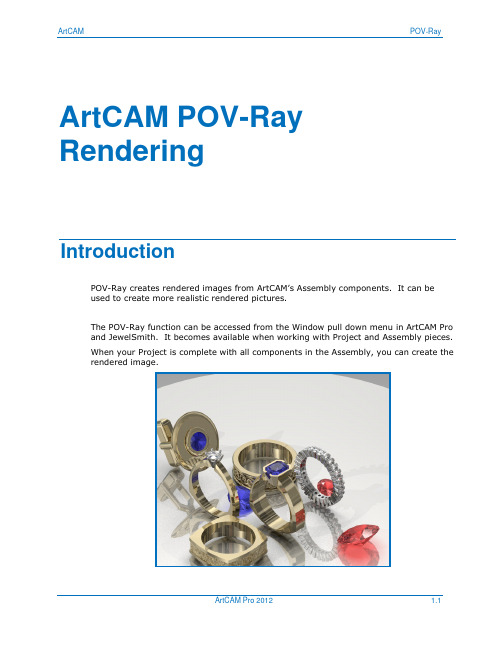
A reflective plate can be added into the Assembly to further enhance the final rendering by adding better reflection and colour
Image window setup:
Re-size ArtCAM Screen to make 3D view smaller and sized to match size for image
Can resize entire ArtCAM session screen or only 3D view. Image is captured on size of 3D view. The larger the 3D view is, the better quality the image but the file size is larger and will take longer to render.
The POV-Ray function can be accessed from the Window pull down menu in ArtCAM Pro and JewelSmith. It becomes available when working with Project and Assembly pieces. When your Project is complete with all components in the Assembly, you can create the rendered image.
ArtCAM Pro浮雕教程(上级)共两级

ArtCAM Pro浮雕教程(上级)共两级ArtCAM Pro 内容内容章节页1. 简介 3 – 122. 位图 13 - 343. 矢量 35 - 724. 浮雕 73 - 905.组合浮雕 91 - 108 6. 扫面轮廓 109 - 132 7. 颜色连接 133 - 144 8. 树叶范例 145 – 152 9. 三维文件浮雕和质地 153 - 164 10. 艺术图案范例 165 –176 11. 城堡范例 177 - 186 12. 浮雕编辑 187 - 194 13. 输入 195 - 202 14. 加工浮雕 203 - 228 15. 特征加工 229 - 242 内容 Issue W1/5 , i ArtCAM Pro 1. 简介 16. 二维加工 243 – 262 17. 阴影 263 - 270 18. 环设计 271 – 278 19. 一些有用的工具 279 – 282Delcam 培训教材 Issue W1/5 , 31. 简介 ArtCAM Pro1. 简介简述使用 ArtCAM Pro 可简单、快速地通过二维图像产生复杂的三维模型。
二维图像可为扫描图像,从其它绘图软件输入的图像或是由ArtCAM Pro所产生的图像。
这些图像经编辑后可用来产生三维浮雕。
ArtCAM Pro 中同样包含着浮雕编辑工具以及组合保存的浮雕的工具。
产生三维浮雕后,可产生加工三维浮雕的刀具路径。
可容易地产生多重粗加工、精加工和雕刻加工刀具路径。
可仿真模拟所产生的刀具路径以在正式加工前能直观地查看产品加后的效果。
启动 ArtCAM Pro, 用左鼠标键双击屏幕上的ArtCAM Pro 图标。
4 , Issue W1/5 Delcam 培训教材ArtCAM Pro 1. 简介于是程序自动启动,屏幕上出现下图所示的主视窗:菜单栏主视窗的顶部是菜单栏。
点击菜单栏可打开下拉菜单,下拉菜单中包含有子菜单和命令。
艺术雕刻解决方案Delcam ArtCAM

艺术雕刻解决方案Delcam ArtCAM
佚名
【期刊名称】《《CAD/CAM与制造业信息化》》
【年(卷),期】2008(000)004
【摘要】英国Delcam公司的艺术雕刻解决方案ArtCAM,一贯以功能强大、易学易用而广受好评。
以往的浮雕设计多用于艺术品设计,但DELCAM现将浮雕设计带入到制造产业中,使制造业产品从实用向内外兼修过渡。
【总页数】2页(P58-59)
【正文语种】中文
【中图分类】TP391.7
【相关文献】
1.Delcam解决方案在艺术品仿形设计加工中的应用 [J], 无
2.Delcam产品ArtCAM亮相北京四新展 [J], 无
3.艺术家修养与当代雕刻艺术创新
——以陈礼忠寿山石雕刻艺术为考察中心 [J], 管宁
4.艺术家修养与当代雕刻艺术创新——以陈礼忠寿山石雕刻艺术为考察中心 [J], 管宁
5.DELCAM英国总部正式发布ArtCAM Pro9·0版本 [J],
因版权原因,仅展示原文概要,查看原文内容请购买。
ArtCAM 中文版使用教程

artcam教程(一)简介1. 介绍介绍.ArtCAM Pro 可以从二维矢量或位图生成三维浮雕。
这些矢量和位图可以在ArtCAM里产生,或从其它系统输入。
ArtCAM 可以装载三维模型,并从它们生成浮雕。
ArtCAM Pro 包含了编辑浮雕和存储浮雕的功能。
产生三维浮雕以后,可以生成刀具路径。
不但能够轻松产生初加工、精加工和雕刻的多条刀具路径,还可以模拟刀具路径,这样在加工前就可以看到完成的产品。
培训文档位于C:/Program Files/ArtCAM PRO/Examples、C:/Program Files/ArtCAM PRO/Examples2 和C:/temp中。
进入ArtCAM Pro·鼠标左键双击屏幕上的ArtCAM Pro图标。
不能使用的选项以灰色显示。
可以产生一个新模型,也可以操作一个已经打开的模型或一个打开的图形文件。
·选择产生新的模型。
必须指定模型尺寸,原点位置和分辨率。
分辨率下图为龙的模型在二维查看中被分解成许多小正方形(像素)的模型。
根据使用的命令,每个方框被给予一个高度。
第一个浮雕使用低分辨率,结果在三维查看中无法显示细节。
如果选择高分辨率,模型被分解成更多的像素,在浮雕中可以精确显示更多细节。
·设置高度和宽度为100,分辨率为796 x 796点。
·选择接受。
菜单栏标签工具栏二维查看助手工具栏三维浮雕查看ArtCAM 显示了一个二维查看窗口,下面为三维浮雕查看。
可以在查看模式间轻松切换,通过标签工具栏、助手工具栏,可以获得ArtCAM 命令和帮助。
菜单栏主窗口的顶部为菜单栏。
点击一个菜单项,打开一个包含子菜单的下拉菜单。
如果某个菜单项不能在当前使用,它将以灰色显示。
例如,文件菜单为:输入选项旁边的箭头表示这里有一个子菜单。
某些菜单选项右边有快捷键。
例如,Ctrl键加字母N是打开一个新建模型的快捷键。
标签工具栏在菜单栏的下面有八个标签,它们包含了所有ArtCAM Pro中常用的命令,可以通过点击相应标签获得这些命令。
ArtCAM专业浮雕培训教程(下册)

. 组合浮雕概要我们现在已学会使用形状编辑器产生浮雕,下面我们来学习如何对这些浮雕进行组合以产生形状更复杂的浮雕。
有四种组合浮雕的方法,它们分别是:相加、相减、最高拼合和最低拼合。
组合使用这些方法可产生形状更复杂,效果更逼真的浮雕。
范例此范例非常简单,旨在展示各种不同方法所产生的结果。
.∙使用文件工具栏中的新的模型图标,打开一任意尺寸的新的模型。
∙使用矢量工具栏中的产生圆形和产生矩形图标,在二维查看中产生一圆圈和一长方形。
∙使用形状编辑器设置圆形矢量轮廓为拱形,其它部分使用缺省设置。
∙点击相加按钮,产生浮雕。
所产生的浮雕应如下图所示:∙点击关闭,关闭形状编辑器。
∙使用形状编辑器设置长方形矢量轮廓为平面,开始高度为。
∙点取应用按钮。
∙点取相加按钮。
浮雕现在应如下图所示:为浮雕上的每一像素点计算出一新的高度(本范例为)并将其加到当前浮雕的对应像素点上。
∙点取二维查看视窗中的撤销图标,回到拱形状态。
∙现在我们点取形状编辑器中的相减按钮(此按钮应仍然在屏幕上,如果不在,可再次双击长方形矢量。
对话视窗中的所有设置应没发生变化,因为已将这些设置应用到矢量)。
产生的浮雕应如下图所示:再次为浮雕上的每一像素点计算出一新的高度,但这一次是从当前浮雕上的相应点上减去高度。
由于浮雕在零平面上被减去,因此产生了一带深度的浮雕。
∙点取二维查看视窗中的撤销图标,回到拱形状态。
∙现在我们点取形状编辑器中的最高拼合按钮。
浮雕应如下图所示:这一次既不相加,也不相减,对两个浮雕进行比较,留下两个浮雕中最高的部分。
如:长方形的中部,拱形是最高的;长方形末端,长方形是最高的。
从整体效果上看,即将两个形状的最高的部分组合在了一起。
∙点取二维查看视窗中的撤销图标,回到拱形状态。
∙现在我们点取形状编辑器中的最低拼合按钮。
浮雕应如下图所示:对两个浮雕的高度进行比较,然后留下两个浮雕中最低的部分。
形状编辑器中的这些按钮仅影响矢量或颜色指定的浮雕区域,因此,本范例情况下,长方形的中间比拱形低;而长方形的末端零平面又比长方形低。
ArtCAMArtCAM教程使用技巧和疑难解答

A r t C A M教程使用技巧及疑难解答如果需将下图所示的节点在水平方向对齐:则使用手动方法对齐节点很有效。
为保证对齐精度,我们可采取下述两种方法中的任意一种:方法1:使用捕捉。
1.在所需对齐位置增加一条标线。
2.从主菜单中选取“二维查看”、“按标线捕捉”选项,打开按标线捕捉功能。
3.用左鼠标键选取需对齐的节点,将其拖动到标线上,则节点自动捕捉到标线上。
方法2:手动编辑节点的XY坐标。
1.用右鼠标键点击所需对齐的节点。
2.选取属性。
3.在属性对话方框中输入所需的Y坐标值。
4.选取确定,接受改变。
5.对每个节点重复上述过程。
6.编辑后的节点具有相同的Y坐标,也即节点呈直线排列。
若需将节点在垂直方向对齐,用上述同样方法改变X坐标值即可。
返回顶部Q2.如何通过阳模浮雕产生阴模浮雕?阳模和阴模代表了一个形体的前后两个部分,在它们中间是一块金属板。
当阳模和阴模压在一起时,就迫使金属板呈现出阳模和阴模的形状。
如果我们需使用已有的浮雕阳模来产生浮雕阴模,则首先需将阳模偏置,然后再将它进行转换。
在此我们来详细地描述如何通过阳模浮雕来产生一阴模浮雕。
1.首先保存好阳模浮雕。
(防止因疏忽使阳模浮雕被由它所产生的阴模浮雕所覆盖)2.从浮雕编辑工具栏中选取浮雕偏置图标,于是打开偏置浮雕对话视窗。
3.在偏置方向选项中选取向外,同时指定一偏置距离。
(例如,若希望使用此套模具压出厚度为1mm的浮雕,则需输入偏置距离1mm,也即当阳模和阴模同时压制金属板时,在阴模和阳模?浯嬖谝?mm的恒定??隙)。
此间隙将产生阴模的底座。
4.点取转换图标,于是产生一个原浮雕的镜像浮雕。
将此浮雕保存为阴模(切勿覆盖阳模) 。
阳模阴模返回顶部Q3. 是否一定要通过阳模来产生阴模浮雕或是一定需通过阴模来产生阳模浮雕?应首先产生用于挤压出精细细节的那一面浮雕。
例如,如果我们希望挤压出一胸针,那么阴模上的细节(前面)比阳模上的细节(背面)更重要。
因此,我们需首先产生阴模浮雕,然后将它偏置,最后通过它转换成阳模浮雕。
- 1、下载文档前请自行甄别文档内容的完整性,平台不提供额外的编辑、内容补充、找答案等附加服务。
- 2、"仅部分预览"的文档,不可在线预览部分如存在完整性等问题,可反馈申请退款(可完整预览的文档不适用该条件!)。
- 3、如文档侵犯您的权益,请联系客服反馈,我们会尽快为您处理(人工客服工作时间:9:00-18:30)。
19. 环设计
综述
使用浮雕工具栏中的产生环形图标可将平面浮雕自动地绕X轴或Y轴环绕而形成一闭合的环形浮雕。
在此仅阴影显示绕好的环而不显示基础浮雕。
和普通浮雕一样,在三维查看中也可不显示Z轴零平面。
改变三维查看工具栏中的低细节,中细节和高细节图标,可改变环的颜色阴影质量。
树控制视窗中将会出现绕好的环分支。
在树控制视窗中用右鼠标键点击绕好的环可调出绘制、删除、保存和隐藏选项菜单。
绕好的环将保存为扩展名为.rng的文件,此文件可输出到ArtSTL 。
对基础浮雕的任何改动,例如增加文件浮雕和质地都将自动地更新到环浮雕上。
使用三维查看工具栏中的显示元素图标,可选取是否显示或不显示浮雕和绕好的环。
范例
∙使用文件工具栏中的新的模型图标打开一新的模型。
于是屏幕上出现新的模型尺寸对话视窗:
∙设置高度为25mm,宽度为100mm,分辨率为800 x 200。
∙点取接受。
于是屏幕上出现下图所示的二维查看。
∙使用矢量工具栏中的产生折线和产生椭圆/圆图标,产生下图所示的矢量形状。
我们将使用扫面轮廓向导来用这些矢量形状产生浮雕。
∙在浮雕工具栏中点取挤出图标。
∙选取直线矢量。
∙点取选取按钮。
∙点取下一步按钮。
∙选取开始轮廓
∙点取选取按钮。
∙点取沿Z轴逆向曲线方向方框。
∙点取下一步按钮。
∙因为端部轮廓和开始轮廓相同,因此点取下一步按钮。
∙将不使用Z轴调整轮廓,因此点取下一步按钮。
∙点取挤出按钮。
于是在三维查看中产生一下图所示的浮雕。
∙在浮雕工具栏中点取产生环形图标。
于是在三维查看中出现一绕好的环。
∙在三维查看工具栏中点取显示零平面和高细节图标,可得到一更好质量的浮雕。
绕好的环的浮雕应如下图所示:
注:从上面范例我们可以看到,产生环浮雕时,环浮雕的光顺连接非常重要。
保存包裹环浮雕
∙在树控制视窗中用右鼠标键点击绕好的环分支。
于是屏幕上弹出下图所示的菜单:
∙选取保存选项。
于是屏幕上出现保存包裹浮雕对话视窗。
∙为浮雕取一个合适的名称,将它保存到目录d/users 下。
∙点取保存按钮。
ISO-型文字
下面我们将使用Iso- 型文字在刚才设计的环浮雕上加上一些文字。
使用位图和颜色结合来产生文字往往导致文字中较薄的部分比浮雕的其它部分低。
Iso-型文字可产生由用户定义的恒定高度的文字。
由于环是使用扫面轮廓产生,因此我们首先需为浮雕产生一灰度图像。
∙从模型工具栏中点取由浮雕产生灰度图像图标。
∙使用矢量工具栏中的产生矢量文字图标,在二维查看中产生一些文字。
∙如下图所示,将文字置于环的中心部位。
∙选取文字,在浮雕工具栏中点取Iso- 形文字图标。
于是屏幕上出现如下对话视窗:
∙文字的顶部高度取决于树控制视窗中当前的浮雕高度。
∙点取接受。
于是浮雕应如下图所示:
使用三维查看工具栏中的显示元素图标,可隐藏一般浮雕。
ArtCAM Pro 19. 环设计放大文字可看到,文字具有恒定的高度。
19. 环设计ArtCAM Pro。