DENO-23-0001;DENO-25-0001;中文规格书,Datasheet资料
Keysight产品附件说明书

DCA 附件N1027A 套件和通用部件使用合适的附件更有助于数字通信分析仪(DCA) 实现高精度测试。
本文列出了建议86100D/N1000A DCA-X 主机及其模块、N109XX DCA-M 和 N107XX 时钟恢复模块使用的附件,包括:•衰减器、直流阻断器•校准套件、负载、短路件、端子•适配器和连接器保护器•相位匹配电缆套件、均衡器•功率分配器/功分器、传感器•机架安装套件、收纳与防护附件•力矩扳手和其他工具除非另有说明,所有附件均与主产品分开销售。
目录N1027A 套件和通用部件 (1)用于电气通道的附件套件 (4)用于 N1045A 和 N1046B 远程探头前端模块的 N1027A-45A 演示套件 (4)用于 N1046A 远程探头前端模块的 N1027A-46A 演示套件 (5)N1027A-AxF 附件套件,随 N1046A 模块一同发货 (5)N1060-60005 附件套件,随 N1060A 模块一同发货 (6)用于 TDR/TDT 模块的附件套件 (7)N1027A-34F/34M/54F/54M TDR/TDT 附件套件 (7)电子校准件 (8)机械校准套件 (9)时钟恢复仪器的附件套件 (10)N1076A-CR1(再次订货编号:N1027A-76A) (10)N1076B-CR1(再次订货编号:N1027A-76B) (11)N1077A-CR1(再次订货编号:N1027A-77A) (11)N1078A-CR1(再次订货编号:N1027A-78A) (12)射频/微波部件 (13)适配器 (13)衰减器 (14)线缆 (15)输入保护帽 (15)直流阻断器 (15)均衡器 (15)相位微调器 (16)传感器 (16)功率分配器/功分器 (16)端子 (16)机械附件 (17)挡板 (17)机架安装套件 (17)远程探头前端附件夹 (17)储存 (17)工具 (18)其他附件 (18)演示和培训器件 (18)防静电(ESD) (19)USB 器件 (19)附录 (20)DCA 输入连接器 (20)光接口 (21)射频/微波连接器 (22)NMD 连接器 (22)3.5 mm 连接器 (22)2.92 mm 连接器 (22)2.4 mm 连接器 (22)1.85 mm 连接器 (22)1.0 mm 连接器 (23)连接器汇总 (23)参考文献 (24)网络资源 (24)用于电气通道的附件套件用于 N1045A 和 N1046B 远程探头前端模块的 N1027A-45A 演示套件N1027A-45A用于 N1046A 远程探头前端模块的 N1027A-46A 演示套件N1027A-AxF 附件套件,随 N1046A 模块一同发货N1027A-A4FN1060-60005 附件套件,随 N1060A 模块一同发货N1060A 模块配有 1.0 mm 阳头加固型连接器。
DENSO新盘点枪使用介绍材料
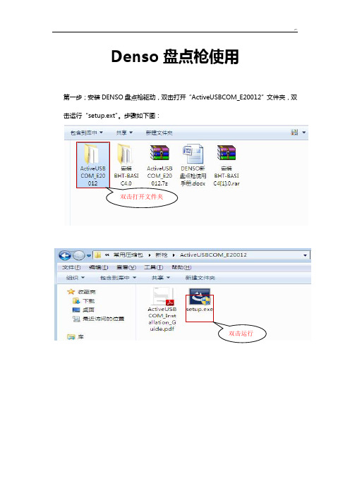
Denso盘点枪使用第一步;安装DENSO盘点枪驱动,双击打开“ActiveUSBCOM_E20012”文件夹,双击运行“setup.ext”。
步骤如下图:双击打开文件夹双击运行请选择“允许本次操作”注:若出现上图时,杀毒软件会提醒,请选择“允许操作”。
驱动安装完成驱动安装成功后,点击“Finish”。
第二步;DENSO盘点枪与电脑连接。
如下图:第三步;检查盘点枪是否正常连接;选中“我的电脑”→右键选择“属性”→再选择“设备管理器”。
如下图选中“端口(COM和LPT)”及“通用串行总线控制器”,如下图DENSO盘点枪占用COM3口,但尚未连接成功;串行总线中未发现该硬件点击“扫描检测硬件改动”,如下图出现“USB输入设备”有感叹号,说明盘点设备尚未开启电源,或驱动尚未被检测到。
选中带感叹号的“USB输入设备”,右键选择“更新驱动程序软件”选择“自动搜索更新的驱动程序软件”,就可以更新驱动若出现下图时,说明DENSO盘点枪与计算机已经正常连接正常连接Connected第四步,配置DENSO盘点枪软件参数。
如下图双击打开“安装BHT-BASIC4.0”文件夹,双击运行“”双击打开文件夹双击运行打开BHT-BASIC4.0的软件后,选择“Options”,若下图单击Options打开Options修改COM 口及通信传输率注意COM口的修改与前面的设备管理器的COM口需要一致,传输率改为9600。
如下图按“OK”配置完成。
第五步;上传数据。
按盘点枪“上传数据”,出现“数据处理完毕按任何键开始上传”时单击“File”-->“Receive”,如下图修改保存路径及文件名;如下图(以保存到桌面,文件名改为1.txt为例子)再按盘点枪任何键,数据上传,若成功数据会以指定的文件名保存到指定的路径下。
如下图所示盘点枪数据传输成功。
AUTODOME 4000 NDA-4020-PIP 接口挂件 - 布朗安全商品说明书
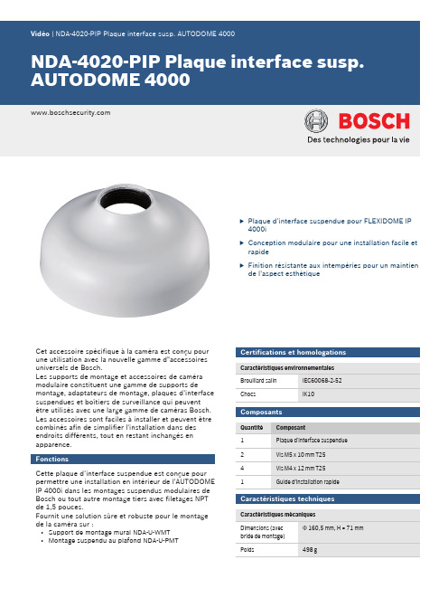
uPlaque d’interface suspendue pour FLEXIDOME IP 4000iuConception modulaire pour une installation facile et rapideuFinition résistante aux intempéries pour un maintien de l'aspect esthétiqueCet accessoire spécifique à la caméra est conçu pour une utilisation avec la nouvelle gamme d"accessoires universels de Bosch.Les supports de montage et accessoires de caméra modulaire constituent une gamme de supports demontage, adaptateurs de montage, plaques d’interface suspendues et boîtiers de surveillance qui peuvent être utilisés avec une large gamme de caméras Bosch.Les accessoires sont faciles à installer et peuvent être combinés afin de simplifier l'installation dans des endroits différents, tout en restant inchangés en apparence.FonctionsCette plaque d’interface suspendue est conçue pour permettre une installation en intérieur de l'AUTODOME IP 4000i dans les montages suspendus modulaires de Bosch ou tout autre montage tiers avec filetages NPT de 1,5 pouces.Fournit une solution sûre et robuste pour le montage de la caméra sur :•Support de montage mural NDA-U-WMT •Montage suspendu au plafond NDA-U-PMTCertifications et homologationsComposantsCaractéristiques techniquesPlaque d’interface suspendue NDA-4020-PIP Dimensions en mmInformations de commandeNDA-4020-PIP Plaque interface susp. AUTODOME 4000 Plaque d'interface suspendue pour AUTODOME IP 4000i.Numéro de commande NDA-4020-PIPAccessoiresNDA-U-PMT Montage suspendu plafond 31cm Montage sur tube universel pour caméras dôme,31 cm, blancNuméro de commande NDA-U-PMTNDA-U-PMTE Extension pour suspension 50cm Extension pour montage sur tube universel, 50 cm, blancNuméro de commande NDA-U-PMTENDA-U-WMT Montage mural suspenduMontage mural universel pour les caméras dôme, blanc Numéro de commande NDA-U-WMT2Représenté par :Europe, Middle East, Africa:Germany:Bosch Security Systems B.V.P.O. Box 800025600 JB Eindhoven, The Netherlands Phone: + 31 40 2577 284****************************** Bosch Sicherheitssysteme GmbH Robert-Bosch-Ring 585630 GrasbrunnGermany© Bosch Security Systems 2017 | Les données sont susceptibles d'être modifiées sans notification préalable. 23065136779 | fr, V5, 18. Oct 2017。
ARTISAN TECHNOLOGY GROUP 质量用途设备来源说明书

DL205PLC User Manual Volume1of2Manual Number:D2-USER-MNotesDL205 PLC USER MANUALNotesVolume One: Table of Contents . . . . . . . . . . . . . . . . . . . . . . . . . . . . . . . .iVolume Two: Table of Contents . . . . . . . . . . . . . . . . . . . . . . . . . . . . . . .xiChapter 1: Getting Started . . . . . . . . . . . . . . . . . . . . . . . . . . . . . . . . . .1–1 Introduction . . . . . . . . . . . . . . . . . . . . . . . . . . . . . . . . . . . . . . . . . . . . . . . . . . . . . . .1–2 The Purpose of this Manual . . . . . . . . . . . . . . . . . . . . . . . . . . . . . . . . . . . . . . . . . . .1–2 Where to Begin . . . . . . . . . . . . . . . . . . . . . . . . . . . . . . . . . . . . . . . . . . . . . . . . . . . .1–2 Supplemental Manuals . . . . . . . . . . . . . . . . . . . . . . . . . . . . . . . . . . . . . . . . . . . . . .1–2 Technical Support . . . . . . . . . . . . . . . . . . . . . . . . . . . . . . . . . . . . . . . . . . . . . . . . . .1–2 Conventions Used . . . . . . . . . . . . . . . . . . . . . . . . . . . . . . . . . . . . . . . . . . . . . . . . . . .1–3 Key Topics for Each Chapter . . . . . . . . . . . . . . . . . . . . . . . . . . . . . . . . . . . . . . . . . .1–3 DL205 System Components . . . . . . . . . . . . . . . . . . . . . . . . . . . . . . . . . . . . . . . . . . .1–4 CPUs . . . . . . . . . . . . . . . . . . . . . . . . . . . . . . . . . . . . . . . . . . . . . . . . . . . . . . . . . . . .1–4 Bases . . . . . . . . . . . . . . . . . . . . . . . . . . . . . . . . . . . . . . . . . . . . . . . . . . . . . . . . . . . .1–4 I/O Configuration . . . . . . . . . . . . . . . . . . . . . . . . . . . . . . . . . . . . . . . . . . . . . . . . . .1–4 I/O Modules . . . . . . . . . . . . . . . . . . . . . . . . . . . . . . . . . . . . . . . . . . . . . . . . . . . . . .1–4 DL205 System Diagrams . . . . . . . . . . . . . . . . . . . . . . . . . . . . . . . . . . . . . . . . . . . . .1–5 Programming Methods . . . . . . . . . . . . . . . . . . . . . . . . . . . . . . . . . . . . . . . . . . . . . . .1–7 Direct SOFT Programming for Windows. . . . . . . . . . . . . . . . . . . . . . . . . . . . . . . . . . .1–7 Handheld Programmer . . . . . . . . . . . . . . . . . . . . . . . . . . . . . . . . . . . . . . . . . . . . . .1–7 Direct LOGIC™ Part Numbering System . . . . . . . . . . . . . . . . . . . . . . . . . . . . . . . . . .1–8 Quick Start for PLC Validation and Programming . . . . . . . . . . . . . . . . . . . . . . . . .1–10 Steps to Designing a Successful System . . . . . . . . . . . . . . . . . . . . . . . . . . . . . . . .1–13Chapter 2: Installation, Wiring and Specifications . . . . . . . . . . . . . . .2–1 Safety Guidelines . . . . . . . . . . . . . . . . . . . . . . . . . . . . . . . . . . . . . . . . . . . . . . . . . . .2–2Table of ContentsPlan for Safety . . . . . . . . . . . . . . . . . . . . . . . . . . . . . . . . . . . . . . . . . . . . . . . . . . . . .2–2 Three Levels of Protection . . . . . . . . . . . . . . . . . . . . . . . . . . . . . . . . . . . . . . . . . . . .2–3 Emergency Stops . . . . . . . . . . . . . . . . . . . . . . . . . . . . . . . . . . . . . . . . . . . . . . . . . . .2–3 Emergency Power Disconnect . . . . . . . . . . . . . . . . . . . . . . . . . . . . . . . . . . . . . . . . .2–4 Orderly System Shutdown . . . . . . . . . . . . . . . . . . . . . . . . . . . . . . . . . . . . . . . . . . . .2–4 Class 1, Division 2, Approval . . . . . . . . . . . . . . . . . . . . . . . . . . . . . . . . . . . . . . . . . .2–4Mounting Guidelines . . . . . . . . . . . . . . . . . . . . . . . . . . . . . . . . . . . . . . . . . . . . . . . .2–5 Base Dimensions . . . . . . . . . . . . . . . . . . . . . . . . . . . . . . . . . . . . . . . . . . . . . . . . . . .2–5 Panel Mounting and Layout . . . . . . . . . . . . . . . . . . . . . . . . . . . . . . . . . . . . . . . . . . .2–6 Enclosures . . . . . . . . . . . . . . . . . . . . . . . . . . . . . . . . . . . . . . . . . . . . . . . . . . . . . . . .2–7 Environmental Specifications . . . . . . . . . . . . . . . . . . . . . . . . . . . . . . . . . . . . . . . . . .2–8 Power . . . . . . . . . . . . . . . . . . . . . . . . . . . . . . . . . . . . . . . . . . . . . . . . . . . . . . . . . . .2–8 Marine Use . . . . . . . . . . . . . . . . . . . . . . . . . . . . . . . . . . . . . . . . . . . . . . . . . . . . . . .2–9 Agency Approvals . . . . . . . . . . . . . . . . . . . . . . . . . . . . . . . . . . . . . . . . . . . . . . . . . .2–924 VDC Power Bases . . . . . . . . . . . . . . . . . . . . . . . . . . . . . . . . . . . . . . . . . . . . . . .2–9Installing DL205 Bases . . . . . . . . . . . . . . . . . . . . . . . . . . . . . . . . . . . . . . . . . . . . . .2–10 Choosing the Base Type . . . . . . . . . . . . . . . . . . . . . . . . . . . . . . . . . . . . . . . . . . . .2–10 Mounting the Base . . . . . . . . . . . . . . . . . . . . . . . . . . . . . . . . . . . . . . . . . . . . . . . .2–10 Using Mounting Rails . . . . . . . . . . . . . . . . . . . . . . . . . . . . . . . . . . . . . . . . . . . . . . .2–11Installing Components in the Base . . . . . . . . . . . . . . . . . . . . . . . . . . . . . . . . . . . .2–12Base Wiring Guidelines . . . . . . . . . . . . . . . . . . . . . . . . . . . . . . . . . . . . . . . . . . . . . .2–13 Base Wiring . . . . . . . . . . . . . . . . . . . . . . . . . . . . . . . . . . . . . . . . . . . . . . . . . . . . . .2–13I/O Wiring Strategies . . . . . . . . . . . . . . . . . . . . . . . . . . . . . . . . . . . . . . . . . . . . . . .2–14 PLC Isolation Boundaries . . . . . . . . . . . . . . . . . . . . . . . . . . . . . . . . . . . . . . . . . . . .2–14 Powering I/O Circuits with the Auxiliary Supply . . . . . . . . . . . . . . . . . . . . . . . . . . .2–15 Powering I/O Circuits Using Separate Supplies . . . . . . . . . . . . . . . . . . . . . . . . . . .2–16 Sinking / Sourcing Concepts . . . . . . . . . . . . . . . . . . . . . . . . . . . . . . . . . . . . . . . . .2–17 I/O “Common” Terminal Concepts . . . . . . . . . . . . . . . . . . . . . . . . . . . . . . . . . . . .2–18 Connecting DC I/O to “Solid State” Field Devices . . . . . . . . . . . . . . . . . . . . . . . . .2–19 Solid State Input Sensors . . . . . . . . . . . . . . . . . . . . . . . . . . . . . . . . . . . . . . . . . . . .2–19 Solid State Output Loads . . . . . . . . . . . . . . . . . . . . . . . . . . . . . . . . . . . . . . . . . . . .2–19 Relay Output Guidelines . . . . . . . . . . . . . . . . . . . . . . . . . . . . . . . . . . . . . . . . . . . .2–21 Surge Suppression For Inductive Loads . . . . . . . . . . . . . . . . . . . . . . . . . . . . . . . . .2–21I/O Modules Position, Wiring, and Specification . . . . . . . . . . . . . . . . . . . . . . . . . .2–25 Slot Numbering . . . . . . . . . . . . . . . . . . . . . . . . . . . . . . . . . . . . . . . . . . . . . . . . . . .2–25 Module Placement Restrictions . . . . . . . . . . . . . . . . . . . . . . . . . . . . . . . . . . . . . . .2–25Table of ContentsSpecial Placement Considerations for Analog Modules . . . . . . . . . . . . . . . . . . . . .2–26 Discrete Input Module Status Indicators . . . . . . . . . . . . . . . . . . . . . . . . . . . . . . . .2–26 Color Coding of I/O Modules . . . . . . . . . . . . . . . . . . . . . . . . . . . . . . . . . . . . . . . .2–26 Wiring the Different Module Connectors . . . . . . . . . . . . . . . . . . . . . . . . . . . . . . . .2–27 I/O Wiring Checklist . . . . . . . . . . . . . . . . . . . . . . . . . . . . . . . . . . . . . . . . . . . . . . . .2–28D2-08ND3, DC Input . . . . . . . . . . . . . . . . . . . . . . . . . . . . . . . . . . . . . . . . . . . . . . . .2–29D2-16ND3-2, DC Input . . . . . . . . . . . . . . . . . . . . . . . . . . . . . . . . . . . . . . . . . . . . . .2–29D2–32ND3, DC Input . . . . . . . . . . . . . . . . . . . . . . . . . . . . . . . . . . . . . . . . . . . . . . .2–30D2–32ND3–2, DC Input . . . . . . . . . . . . . . . . . . . . . . . . . . . . . . . . . . . . . . . . . . . . .2–31D2-08NA-1, AC Input . . . . . . . . . . . . . . . . . . . . . . . . . . . . . . . . . . . . . . . . . . . . . . .2–32D2-08NA-2, AC Input . . . . . . . . . . . . . . . . . . . . . . . . . . . . . . . . . . . . . . . . . . . . . . .2–33D2-16NA, AC Input . . . . . . . . . . . . . . . . . . . . . . . . . . . . . . . . . . . . . . . . . . . . . . . . .2–34F2-08SIM, Input Simulator . . . . . . . . . . . . . . . . . . . . . . . . . . . . . . . . . . . . . . . . . . .2–34D2-04TD1, DC Output . . . . . . . . . . . . . . . . . . . . . . . . . . . . . . . . . . . . . . . . . . . . . .2–35D2–08TD1, DC Output . . . . . . . . . . . . . . . . . . . . . . . . . . . . . . . . . . . . . . . . . . . . . .2–36D2–08TD2, DC Output . . . . . . . . . . . . . . . . . . . . . . . . . . . . . . . . . . . . . . . . . . . . . .2–36D2–16TD1–2, DC Output . . . . . . . . . . . . . . . . . . . . . . . . . . . . . . . . . . . . . . . . . . . .2–37D2–16TD2–2, DC Output . . . . . . . . . . . . . . . . . . . . . . . . . . . . . . . . . . . . . . . . . . . .2–37F2–16TD1(2)P, DC Output With Fault Protection . . . . . . . . . . . . . . . . . . . . . . . . .2–38F2–16TD1P, DC Output With Fault Protection . . . . . . . . . . . . . . . . . . . . . . . . . . .2–39F2–16TD2P, DC Output with Fault Protection . . . . . . . . . . . . . . . . . . . . . . . . . . . .2–40D2–32TD1, DC Output . . . . . . . . . . . . . . . . . . . . . . . . . . . . . . . . . . . . . . . . . . . . . .2–41D2–32TD2, DC Output . . . . . . . . . . . . . . . . . . . . . . . . . . . . . . . . . . . . . . . . . . . . . .2–41F2–08TA, AC Output . . . . . . . . . . . . . . . . . . . . . . . . . . . . . . . . . . . . . . . . . . . . . . . .2–42D2–08TA, AC Output . . . . . . . . . . . . . . . . . . . . . . . . . . . . . . . . . . . . . . . . . . . . . . .2–42D2–12TA, AC Output . . . . . . . . . . . . . . . . . . . . . . . . . . . . . . . . . . . . . . . . . . . . . . . .2–43D2–04TRS, Relay Output . . . . . . . . . . . . . . . . . . . . . . . . . . . . . . . . . . . . . . . . . . . . .2–44D2–08TR, Relay Output . . . . . . . . . . . . . . . . . . . . . . . . . . . . . . . . . . . . . . . . . . . . . .2–45F2–08TR, Relay Output . . . . . . . . . . . . . . . . . . . . . . . . . . . . . . . . . . . . . . . . . . . . . .2–46F2–08TRS, Relay Output . . . . . . . . . . . . . . . . . . . . . . . . . . . . . . . . . . . . . . . . . . . . .2–47D2–12TR, Relay Output . . . . . . . . . . . . . . . . . . . . . . . . . . . . . . . . . . . . . . . . . . . . . .2–48 D2–08CDR 4 pt., DC Input / 4pt., Relay Output . . . . . . . . . . . . . . . . . . . . . . . . . .2–49 Glossary of Specification Terms . . . . . . . . . . . . . . . . . . . . . . . . . . . . . . . . . . . . . . .2–50Chapter 3: CPU Specifications and Operations . . . . . . . . . . . . . . . . . .3–1 CPU Overview . . . . . . . . . . . . . . . . . . . . . . . . . . . . . . . . . . . . . . . . . . . . . . . . . . . . . .3–2 General CPU Features . . . . . . . . . . . . . . . . . . . . . . . . . . . . . . . . . . . . . . . . . . . . . . .3–2 DL230 CPU Features . . . . . . . . . . . . . . . . . . . . . . . . . . . . . . . . . . . . . . . . . . . . . . . .3–2 DL240 CPU Features . . . . . . . . . . . . . . . . . . . . . . . . . . . . . . . . . . . . . . . . . . . . . . . .3–2 DL250–1 CPU Features . . . . . . . . . . . . . . . . . . . . . . . . . . . . . . . . . . . . . . . . . . . . . .3–3 DL260 CPU Features . . . . . . . . . . . . . . . . . . . . . . . . . . . . . . . . . . . . . . . . . . . . . . . .3–3CPU General Specifications . . . . . . . . . . . . . . . . . . . . . . . . . . . . . . . . . . . . . . . . . . .3–4 CPU Base Electrical Specifications . . . . . . . . . . . . . . . . . . . . . . . . . . . . . . . . . . . . . .3–5 CPU Hardware Setup . . . . . . . . . . . . . . . . . . . . . . . . . . . . . . . . . . . . . . . . . . . . . . . .3–6 Communication Port Pinout Diagrams . . . . . . . . . . . . . . . . . . . . . . . . . . . . . . . . . . .3–6 Port 1 Specifications . . . . . . . . . . . . . . . . . . . . . . . . . . . . . . . . . . . . . . . . . . . . . . . .3–7 Port 2 Specifications . . . . . . . . . . . . . . . . . . . . . . . . . . . . . . . . . . . . . . . . . . . . . . . .3–8 Selecting the Program Storage Media . . . . . . . . . . . . . . . . . . . . . . . . . . . . . . . . . . .3–9 Built-in EEPROM . . . . . . . . . . . . . . . . . . . . . . . . . . . . . . . . . . . . . . . . . . . . . . . . . . .3–9 EEPROM Sizes . . . . . . . . . . . . . . . . . . . . . . . . . . . . . . . . . . . . . . . . . . . . . . . . . . . . .3–9 EEPROM Operations . . . . . . . . . . . . . . . . . . . . . . . . . . . . . . . . . . . . . . . . . . . . . . . .3–9 Installing the CPU . . . . . . . . . . . . . . . . . . . . . . . . . . . . . . . . . . . . . . . . . . . . . . . . .3–10 Connecting the Programming Devices . . . . . . . . . . . . . . . . . . . . . . . . . . . . . . . . .3–10 CPU Setup Information . . . . . . . . . . . . . . . . . . . . . . . . . . . . . . . . . . . . . . . . . . . . .3–11 Status Indicators . . . . . . . . . . . . . . . . . . . . . . . . . . . . . . . . . . . . . . . . . . . . . . . . . .3–12 Mode Switch Functions . . . . . . . . . . . . . . . . . . . . . . . . . . . . . . . . . . . . . . . . . . . . .3–12 Changing Modes in the DL205 PLC . . . . . . . . . . . . . . . . . . . . . . . . . . . . . . . . . . .3–13 Mode of Operation at Power-up . . . . . . . . . . . . . . . . . . . . . . . . . . . . . . . . . . . . . .3–13Using Battery Backup . . . . . . . . . . . . . . . . . . . . . . . . . . . . . . . . . . . . . . . . . . . . . . .3–14 DL230 and DL240 . . . . . . . . . . . . . . . . . . . . . . . . . . . . . . . . . . . . . . . . . . . . . . . . .3–14 DL250-1 and DL260 . . . . . . . . . . . . . . . . . . . . . . . . . . . . . . . . . . . . . . . . . . . . . . .3–14 Battery Backup . . . . . . . . . . . . . . . . . . . . . . . . . . . . . . . . . . . . . . . . . . . . . . . . . . . .3–14 Auxiliary Functions . . . . . . . . . . . . . . . . . . . . . . . . . . . . . . . . . . . . . . . . . . . . . . . . .3–15 Clearing an Existing Program . . . . . . . . . . . . . . . . . . . . . . . . . . . . . . . . . . . . . . . . .3–16 Initializing System Memory . . . . . . . . . . . . . . . . . . . . . . . . . . . . . . . . . . . . . . . . . .3–16Setting the Clock and Calendar . . . . . . . . . . . . . . . . . . . . . . . . . . . . . . . . . . . . . . .3–16 Setting the CPU Network Address . . . . . . . . . . . . . . . . . . . . . . . . . . . . . . . . . . . . .3–17 Setting Retentive Memory Ranges . . . . . . . . . . . . . . . . . . . . . . . . . . . . . . . . . . . . .3–17 Using a Password . . . . . . . . . . . . . . . . . . . . . . . . . . . . . . . . . . . . . . . . . . . . . . . . . .3–18 Setting the Analog Potentiometer Ranges . . . . . . . . . . . . . . . . . . . . . . . . . . . . . . .3–19 CPU Operation . . . . . . . . . . . . . . . . . . . . . . . . . . . . . . . . . . . . . . . . . . . . . . . . . . . .3–21 CPU Operating System . . . . . . . . . . . . . . . . . . . . . . . . . . . . . . . . . . . . . . . . . . . . .3–21 Program Mode Operation . . . . . . . . . . . . . . . . . . . . . . . . . . . . . . . . . . . . . . . . . . .3–22 Run Mode Operation . . . . . . . . . . . . . . . . . . . . . . . . . . . . . . . . . . . . . . . . . . . . . . .3–22 Read Inputs . . . . . . . . . . . . . . . . . . . . . . . . . . . . . . . . . . . . . . . . . . . . . . . . . . . . . .3–23 Read Inputs from Specialty and Remote I/O . . . . . . . . . . . . . . . . . . . . . . . . . . . . .3–23 Service Peripherals and Force I/O . . . . . . . . . . . . . . . . . . . . . . . . . . . . . . . . . . . . . .3–23 CPU Bus Communication . . . . . . . . . . . . . . . . . . . . . . . . . . . . . . . . . . . . . . . . . . .3–24 Update Clock, Special Relays and Special Registers . . . . . . . . . . . . . . . . . . . . . . . .3–24 Solve Application Program . . . . . . . . . . . . . . . . . . . . . . . . . . . . . . . . . . . . . . . . . . .3–25 Solve PID Loop Equations . . . . . . . . . . . . . . . . . . . . . . . . . . . . . . . . . . . . . . . . . . .3–25 Write Outputs . . . . . . . . . . . . . . . . . . . . . . . . . . . . . . . . . . . . . . . . . . . . . . . . . . . .3–25 Write Outputs to Specialty and Remote I/O . . . . . . . . . . . . . . . . . . . . . . . . . . . . . .3–26 Diagnostics . . . . . . . . . . . . . . . . . . . . . . . . . . . . . . . . . . . . . . . . . . . . . . . . . . . . . .3–26 I/O Response Time . . . . . . . . . . . . . . . . . . . . . . . . . . . . . . . . . . . . . . . . . . . . . . . . .3–27 Is Timing Important for Your Application? . . . . . . . . . . . . . . . . . . . . . . . . . . . . . . .3–27 Normal Minimum I/O Response . . . . . . . . . . . . . . . . . . . . . . . . . . . . . . . . . . . . . .3–27 Normal Maximum I/O Response . . . . . . . . . . . . . . . . . . . . . . . . . . . . . . . . . . . . . .3–27 Improving Response Time . . . . . . . . . . . . . . . . . . . . . . . . . . . . . . . . . . . . . . . . . . .3–28 CPU Scan Time Considerations . . . . . . . . . . . . . . . . . . . . . . . . . . . . . . . . . . . . . . .3–29 Initialization Process . . . . . . . . . . . . . . . . . . . . . . . . . . . . . . . . . . . . . . . . . . . . . . . .3–30 Reading Inputs . . . . . . . . . . . . . . . . . . . . . . . . . . . . . . . . . . . . . . . . . . . . . . . . . . . .3–30 Reading Inputs from Specialty I/O . . . . . . . . . . . . . . . . . . . . . . . . . . . . . . . . . . . . .3–31 Service Peripherals . . . . . . . . . . . . . . . . . . . . . . . . . . . . . . . . . . . . . . . . . . . . . . . . .3–31 CPU Bus Communication . . . . . . . . . . . . . . . . . . . . . . . . . . . . . . . . . . . . . . . . . . .3–32 Update Clock/Calendar, Special Relays, Special Registers . . . . . . . . . . . . . . . . . . . .3–32 Writing Outputs . . . . . . . . . . . . . . . . . . . . . . . . . . . . . . . . . . . . . . . . . . . . . . . . . . .3–32 Writing Outputs to Specialty I/O . . . . . . . . . . . . . . . . . . . . . . . . . . . . . . . . . . . . . .3–33 Diagnostics . . . . . . . . . . . . . . . . . . . . . . . . . . . . . . . . . . . . . . . . . . . . . . . . . . . . . .3–33 Application Program Execution . . . . . . . . . . . . . . . . . . . . . . . . . . . . . . . . . . . . . . .3–34 PLC Numbering Systems . . . . . . . . . . . . . . . . . . . . . . . . . . . . . . . . . . . . . . . . . . . . .3–35PLC Resources . . . . . . . . . . . . . . . . . . . . . . . . . . . . . . . . . . . . . . . . . . . . . . . . . . . .3–35 V–Memory . . . . . . . . . . . . . . . . . . . . . . . . . . . . . . . . . . . . . . . . . . . . . . . . . . . . . . .3–36 Binary-Coded Decimal Numbers . . . . . . . . . . . . . . . . . . . . . . . . . . . . . . . . . . . . . .3–36 Hexadecimal Numbers . . . . . . . . . . . . . . . . . . . . . . . . . . . . . . . . . . . . . . . . . . . . . .3–36Memory Map . . . . . . . . . . . . . . . . . . . . . . . . . . . . . . . . . . . . . . . . . . . . . . . . . . . . . .3–37 Octal Numbering System . . . . . . . . . . . . . . . . . . . . . . . . . . . . . . . . . . . . . . . . . . .3–37 Discrete and Word Locations . . . . . . . . . . . . . . . . . . . . . . . . . . . . . . . . . . . . . . . . .3–37 V–Memory Locations for Discrete Memory Areas . . . . . . . . . . . . . . . . . . . . . . . . . .3–37 Input Points (X Data Type) . . . . . . . . . . . . . . . . . . . . . . . . . . . . . . . . . . . . . . . . . .3–38 Output Points (Y Data Type) . . . . . . . . . . . . . . . . . . . . . . . . . . . . . . . . . . . . . . . . .3–38 Control Relays (C Data Type) . . . . . . . . . . . . . . . . . . . . . . . . . . . . . . . . . . . . . . . . .3–38 Timers and Timer Status Bits (T Data type) . . . . . . . . . . . . . . . . . . . . . . . . . . . . . .3–38 Timer Current Values (V Data Type) . . . . . . . . . . . . . . . . . . . . . . . . . . . . . . . . . . . .3–39 Counters and Counter Status Bits (CT Data type) . . . . . . . . . . . . . . . . . . . . . . . . .3–39 Counter Current Values (V Data Type) . . . . . . . . . . . . . . . . . . . . . . . . . . . . . . . . . .3–39 Word Memory (V Data Type) . . . . . . . . . . . . . . . . . . . . . . . . . . . . . . . . . . . . . . . . .3–39 Stages (S Data type) . . . . . . . . . . . . . . . . . . . . . . . . . . . . . . . . . . . . . . . . . . . . . . .3–40 Special Relays (SP Data Type) . . . . . . . . . . . . . . . . . . . . . . . . . . . . . . . . . . . . . . . .3–40 Remote I/O Points (GX Data Type) . . . . . . . . . . . . . . . . . . . . . . . . . . . . . . . . . . . .3–40DL230 System V-memory . . . . . . . . . . . . . . . . . . . . . . . . . . . . . . . . . . . . . . . . . . . .3–41DL240 System V-memory . . . . . . . . . . . . . . . . . . . . . . . . . . . . . . . . . . . . . . . . . . . .3–43DL250–1 System V-memory (DL250 also) . . . . . . . . . . . . . . . . . . . . . . . . . . . . . . .3–46DL260 System V-memory . . . . . . . . . . . . . . . . . . . . . . . . . . . . . . . . . . . . . . . . . . . .3–49DL205 Aliases . . . . . . . . . . . . . . . . . . . . . . . . . . . . . . . . . . . . . . . . . . . . . . . . . . . . .3–52DL230 Memory Map . . . . . . . . . . . . . . . . . . . . . . . . . . . . . . . . . . . . . . . . . . . . . . . .3–53DL240 Memory Map . . . . . . . . . . . . . . . . . . . . . . . . . . . . . . . . . . . . . . . . . . . . . . . .3–54DL250–1 Memory Map (DL250 also) . . . . . . . . . . . . . . . . . . . . . . . . . . . . . . . . . . .3–55DL260 Memory Map . . . . . . . . . . . . . . . . . . . . . . . . . . . . . . . . . . . . . . . . . . . . . . . .3–56X Input/Y Output Bit Map . . . . . . . . . . . . . . . . . . . . . . . . . . . . . . . . . . . . . . . . . . .3–57Control Relay Bit Map . . . . . . . . . . . . . . . . . . . . . . . . . . . . . . . . . . . . . . . . . . . . . . .3–59Stage Control/Status Bit Map . . . . . . . . . . . . . . . . . . . . . . . . . . . . . . . . . . . . . . . .3–63Timer and Counter Status Bit Maps . . . . . . . . . . . . . . . . . . . . . . . . . . . . . . . . . . . .3–65Remote I/O Bit Map . . . . . . . . . . . . . . . . . . . . . . . . . . . . . . . . . . . . . . . . . . . . . . . .3–66Chapter 4: System Design and Configuration . . . . . . . . . . . . . . . . . . .4–1DL205 System Design Strategies . . . . . . . . . . . . . . . . . . . . . . . . . . . . . . . . . . . . . . .4–2 I/O System Configurations . . . . . . . . . . . . . . . . . . . . . . . . . . . . . . . . . . . . . . . . . . . .4–2 Networking Configurations . . . . . . . . . . . . . . . . . . . . . . . . . . . . . . . . . . . . . . . . . . .4–2Module Placement . . . . . . . . . . . . . . . . . . . . . . . . . . . . . . . . . . . . . . . . . . . . . . . . . .4–3 Slot Numbering . . . . . . . . . . . . . . . . . . . . . . . . . . . . . . . . . . . . . . . . . . . . . . . . . . . .4–3 Module Placement Restrictions . . . . . . . . . . . . . . . . . . . . . . . . . . . . . . . . . . . . . . . .4–3 Automatic I/O Configuration . . . . . . . . . . . . . . . . . . . . . . . . . . . . . . . . . . . . . . . . . .4–4 Manual I/O Configuration . . . . . . . . . . . . . . . . . . . . . . . . . . . . . . . . . . . . . . . . . . . .4–4 Removing a Manual Configuration . . . . . . . . . . . . . . . . . . . . . . . . . . . . . . . . . . . . .4–5 Power–On I/O Configuration Check . . . . . . . . . . . . . . . . . . . . . . . . . . . . . . . . . . . .4–5 I/O Points Required for Each Module . . . . . . . . . . . . . . . . . . . . . . . . . . . . . . . . . . . .4–6Calculating the Power Budget . . . . . . . . . . . . . . . . . . . . . . . . . . . . . . . . . . . . . . . . .4–7 Managing your Power Resource . . . . . . . . . . . . . . . . . . . . . . . . . . . . . . . . . . . . . . .4–7 CPU Power Specifications . . . . . . . . . . . . . . . . . . . . . . . . . . . . . . . . . . . . . . . . . . . .4–7 Module Power Requirements . . . . . . . . . . . . . . . . . . . . . . . . . . . . . . . . . . . . . . . . . .4–7 Power Budget Calculation Example . . . . . . . . . . . . . . . . . . . . . . . . . . . . . . . . . . . . .4–9 Power Budget Calculation Worksheet . . . . . . . . . . . . . . . . . . . . . . . . . . . . . . . . . .4–10 Local Expansion I/O . . . . . . . . . . . . . . . . . . . . . . . . . . . . . . . . . . . . . . . . . . . . . . . .4–11 D2–CM Local Expansion Module . . . . . . . . . . . . . . . . . . . . . . . . . . . . . . . . . . . . . .4–11 D2–EM Local Expansion Module . . . . . . . . . . . . . . . . . . . . . . . . . . . . . . . . . . . . . .4–12 D2–EXCBL–1 Local Expansion Cable . . . . . . . . . . . . . . . . . . . . . . . . . . . . . . . . . . .4–12 DL260 Local Expansion System . . . . . . . . . . . . . . . . . . . . . . . . . . . . . . . . . . . . . . .4–13 DL250–1 Local Expansion System . . . . . . . . . . . . . . . . . . . . . . . . . . . . . . . . . . . . .4–14 Expansion Base Output Hold Option . . . . . . . . . . . . . . . . . . . . . . . . . . . . . . . . . . .4–15 Enabling I/O Configuration Check using Direct SOFT . . . . . . . . . . . . . . . . . . . . . . .4–16 Expanding DL205 I/O . . . . . . . . . . . . . . . . . . . . . . . . . . . . . . . . . . . . . . . . . . . . . . .4–17 I/O Expansion Overview . . . . . . . . . . . . . . . . . . . . . . . . . . . . . . . . . . . . . . . . . . . .4–17 Ethernet Remote Master, H2-ERM(-F) . . . . . . . . . . . . . . . . . . . . . . . . . . . . . . . . . .4–17 Ethernet Remote Master Hardware Configuration . . . . . . . . . . . . . . . . . . . . . . . . .4–18 Installing the ERM Module . . . . . . . . . . . . . . . . . . . . . . . . . . . . . . . . . . . . . . . . . . .4–19 Ethernet Base Controller, H2-EBC(100)(-F) . . . . . . . . . . . . . . . . . . . . . . . . . . . . . . .4–22 Install the EBC Module . . . . . . . . . . . . . . . . . . . . . . . . . . . . . . . . . . . . . . . . . . . . .4–23 Set the Module ID . . . . . . . . . . . . . . . . . . . . . . . . . . . . . . . . . . . . . . . . . . . . . . . . .4–23 Insert the EBC Module . . . . . . . . . . . . . . . . . . . . . . . . . . . . . . . . . . . . . . . . . . . . . .4–23 Network Cabling . . . . . . . . . . . . . . . . . . . . . . . . . . . . . . . . . . . . . . . . . . . . . . . . . .4–2410BaseFL Network Cabling . . . . . . . . . . . . . . . . . . . . . . . . . . . . . . . . . . . . . . . . . .4–25 Maximum Cable Length . . . . . . . . . . . . . . . . . . . . . . . . . . . . . . . . . . . . . . . . . . . .4–25 Add a Serial Remote I/O Master/Slave Module . . . . . . . . . . . . . . . . . . . . . . . . . . .4–26 Configuring the CPU’s Remote I/O Channel . . . . . . . . . . . . . . . . . . . . . . . . . . . . .4–27 Configure Remote I/O Slaves . . . . . . . . . . . . . . . . . . . . . . . . . . . . . . . . . . . . . . . . .4–29 Configuring the Remote I/O Table . . . . . . . . . . . . . . . . . . . . . . . . . . . . . . . . . . . . .4–29 Remote I/O Setup Program . . . . . . . . . . . . . . . . . . . . . . . . . . . . . . . . . . . . . . . . . .4–30 Remote I/O Test Program . . . . . . . . . . . . . . . . . . . . . . . . . . . . . . . . . . . . . . . . . . .4–31 Network Connections to Modbus and Direct Net . . . . . . . . . . . . . . . . . . . . . . . . . .4–32 Configuring Port 2 For Direct Net . . . . . . . . . . . . . . . . . . . . . . . . . . . . . . . . . . . . . .4–32 Configuring Port 2 For Modbus RTU . . . . . . . . . . . . . . . . . . . . . . . . . . . . . . . . . . .4–32 Modbus Port Configuration . . . . . . . . . . . . . . . . . . . . . . . . . . . . . . . . . . . . . . . . . .4–33 Direct NET Port Configuration . . . . . . . . . . . . . . . . . . . . . . . . . . . . . . . . . . . . . . . .4–34 Network Slave Operation . . . . . . . . . . . . . . . . . . . . . . . . . . . . . . . . . . . . . . . . . . . .4–35 Modbus Function Codes Supported . . . . . . . . . . . . . . . . . . . . . . . . . . . . . . . . . . .4–35 Determining the Modbus Address . . . . . . . . . . . . . . . . . . . . . . . . . . . . . . . . . . . . .4–35 If Your Host Software Requires the Data Type and Address . . . . . . . . . . . . . . . . . .4–35 If Your Modbus Host Software Requires an Address ONLY . . . . . . . . . . . . . . . . . . .4–38 Example 1: V2100 584/984 Mode . . . . . . . . . . . . . . . . . . . . . . . . . . . . . . . . . . . . .4–40 Example 2: Y20 584/984 Mode . . . . . . . . . . . . . . . . . . . . . . . . . . . . . . . . . . . . . . .4–40 Example 3: T10 Current Value 484 Mode . . . . . . . . . . . . . . . . . . . . . . . . . . . . . . .4–40 Example 4: C54 584/984 Mode . . . . . . . . . . . . . . . . . . . . . . . . . . . . . . . . . . . . . .4–40 Determining the Direct NET Address . . . . . . . . . . . . . . . . . . . . . . . . . . . . . . . . . . . .4–40 Network Master Operation . . . . . . . . . . . . . . . . . . . . . . . . . . . . . . . . . . . . . . . . . .4–41 Communications from a Ladder Program . . . . . . . . . . . . . . . . . . . . . . . . . . . . . . .4–44 Multiple Read and Write Interlocks . . . . . . . . . . . . . . . . . . . . . . . . . . . . . . . . . . . .4–44 Network Modbus RTU Master Operation (DL260 only) . . . . . . . . . . . . . . . . . . . .4–45 Modbus Function Codes Supported . . . . . . . . . . . . . . . . . . . . . . . . . . . . . . . . . . .4–45 Modbus Port Configuration . . . . . . . . . . . . . . . . . . . . . . . . . . . . . . . . . . . . . . . . . .4–46 RS–485 Network (Modbus only) . . . . . . . . . . . . . . . . . . . . . . . . . . . . . . . . . . . . . .4–47 RS–232 Network . . . . . . . . . . . . . . . . . . . . . . . . . . . . . . . . . . . . . . . . . . . . . . . . . .4–47 Modbus Read from Network (MRX) . . . . . . . . . . . . . . . . . . . . . . . . . . . . . . . . . . . .4–48 MRX Slave Memory Address . . . . . . . . . . . . . . . . . . . . . . . . . . . . . . . . . . . . . . . . .4–49 MRX Master Memory Addresses . . . . . . . . . . . . . . . . . . . . . . . . . . . . . . . . . . . . . .4–49 MRX Number of Elements . . . . . . . . . . . . . . . . . . . . . . . . . . . . . . . . . . . . . . . . . . .4–49 MRX Exception Response Buffer . . . . . . . . . . . . . . . . . . . . . . . . . . . . . . . . . . . . . .4–49 Modbus Write to Network (MWX) . . . . . . . . . . . . . . . . . . . . . . . . . . . . . . . . . . . . .4–50。
MDM2004网关产品说明书

思默康产品选型说明书

温度湿度气体2015价格表德国标准 东方精神壓力照度及位移思默康自动化设备(上海)有限公司价格生效期始于2014年10月15日1.0版TRW1-Series (T)TRW2-Series (T)0…10V / 4…20mANTC / PT / NiTPS1-Series (T)0…10V / 4…20mANTC / PT / NiTOW1-Series (T)TOW2-Series (T)TDE1-Series (T_av)TDE2-Series (T_av)风管温度防凍开关TDE2-Series (T_fp)通用温度有源传感器TUU1-Series (T)0…10V / 4…20mA通用温度无源传感器TUU2-Series (T)HPS2-Series (H_cs) HPS2-Series (H_lg)GDI1-Series (VOC)0…10V湿度:0..10V温度:0..10V可选 NTC ; PT ; NiPDE1- Series (dP_r) PDI1- Series (V&T) PDE2- Series (dP) PPE1- Series ( PPE2- Series (LRC1-Series(L)10V / 4…20mA CRC8-series (L&M)照度:0...10V人体活动:ON/OFF MRW2-Series(M)asia pacific照度及位移传感器温度湿度气体壓力照度及位移价格生效期始于2014年10月15日价格表其他配件德国标准 东方精神asia pacific配件asia pacific安装套件思默康自動化設備(上海)有限公司上海市閔行區莘庄工業區春東路479號C-1廠房2樓電話: (+8621) 5176 0211傳真: (+8621) 5176 0213泰慕康传感器科技有限公司香港新界荃灣168德士古道德豐工業中心2座13/樓10-11室電話: (+852) 3468 8636傳真: (+852) 3621 0002网站: / 邮箱: info@ asia pacific声明该价格表中,对技术信息都进行了简化,并保持随时更新。
Arista 7020 Series 1 RU-Gen 3 Data Center Switches

Chapter5 Configuring the SwitchArista switches ship from the factory in Zero Touch Provisioning(ZTP)mode.ZTP configures the switchwithout user intervention by downloading a startup configuration file or a boot script from a locationspecified by a DHCP server.To manually configure a switch,ZTP is bypassed.The initial configurationprovides one username(admin)accessible only through the console port because it has no password.When bypassing ZTP,initial switch access requires logging in as admin,with no password,through theconsole port.Then you can configure an admin password and other password protected usernames.This manual configuration procedure cancels ZTP mode,logs into the switch,assigns a password toadmin,assigns an IP address to the management port,and defines a default route to a networkgateway.Step1Provide power to the switch(Section4.1).Step2Connect the console port to a PC(Section4.2).As the switch boots without a startup-config file,it displays the following through the console:The device is in Zero Touch Provisioning mode and is attempting todownload the startup-config from a remote system. The device will notbe fully functional until either a valid startup-config is downloadedfrom a remote system or Zero Touch Provisioning is cancelled. To cancelZero Touch Provisioning, login as admin and type 'zerotouch cancel'at the CLI.localhost login:Step3Log into the switch by typing admin at the login prompt.localhost login:adminStep4Cancel ZTP mode by typing zerotouch cancel.IMPORTANT:This step initiates a switch reboot.localhost>zerotouch cancelStep5After the switch boots,log into the switch again by typing admin at the login prompt.Arista EOSlocalhost login:adminLast login: Fri Mar 15 13:17:13 on consoleStep6Enter global configuration mode.localhost>enablelocalhost#configStep7Assign a password to the admin username with the username secret command.localhost(config)#username admin secret pxq123Step8Configure a default route to the network gateway.localhost(config)#ip route 0.0.0.0/0 192.0.2.1Step9Assign an IP address(192.0.2.8/24in this example)to an Ethernet management port.localhost(config)#interface management 1localhost(config-if-Ma1/1)#ip address 192.0.2.8/24Step10Save the configuration by typing write memory or copy running-config startup-config.localhost#copy running-config startup-configWhen the management port IP address is configured,use this command to access the switch from a host,using the address configured in step9:**************.2.8Refer to the Arista Networks User Manual for complete switch configuration information.。
HOA7730-M11;HOA7720-M11;中文规格书,Datasheet资料

HOA7720/7730 SeriesConnectorized Transmissive Optoschmitt SensorDESCRIPTIONThe HOA7720/7730 Series consists of an infrared emittingdiode facing an Optoschmitt detector encased in a black thermoplastic housing. The photodetector consists of a photodiode, amplifier, voltage regulator and Schmitt triggerwith either of two output configurations: Totem pole (HOA7720-M11) Open collector (HOA7730-M11)The totem pole output is well-suited for applications which require fast transition times. The open collector allows the output of the sensor to interface with circuit elements driven by supply voltages other than Vcc supply.The inverting logic provides a high output when the optical path is interrupted, and a low output when the path is clear.The infrared emitting diode is biased internally, eliminating the need for any external circuitry. Interconnection is simplified through the use of the integral Tyco three-pin connector.Both the emitter and detector have a 0.508 mm x 1,78 mm [0.020 in x 0,070 in] vertical aperture. The narrow aperture is ideal for use in applications in which the maximum rejection of ambient light is important, and the maximum position resolution is desired.The HOA7220/7330 series employ plastic molded components. Housing material is opaque polycarbonate. Housings are soluble in chlorinated hydrocarbons and ketones. Recommended cleaning agents are methanol and isopropanol.FEATURES AND BENEFITSDirect TTL interfaceNo interface circuits requiredInverting logicTwo output optionsHigh resolution3.00 mm [0.118] slot widthIntegral 3-pin connectorPOTENTIAL APPLICATIONSIndustrial:Flag presence/absence detection Edge detectionRotary/linear encodersMedical:Edge sensing for labels and paperNeedle presence/absence detection End of motion/travel sensingRotary/linear encodersHOA7720/7730 SeriesTable 1. HOA7720-M11 and HOA7730-M11 Absolute Maximum Ratings (At 25 ºC [77 ºF] free air temperature unless otherwise noted.)Characteristic ParameterOperating temperature range -40 ºC to 70 ºC [-40 ºF to 158 ºF]Storage temperature range -40 ºC to 85 ºC [-40 ºF to 185 ºF]Power dissipation 220 mWSupply voltage 5.5 VSupply current 40 mALow level output current 12.8 mADuration of output: short to Vcc or ground 1.0 sApplied output voltage135 VNotes:1.Applies to HOA7730 only.Table 2. HOA7720-M11 Electrical Characteristics (At 25 ºC [77 ºF] unless otherwise noted.)Characteristic Symbol Min Typ. Max Unit Test ConditionOperating supply voltage1V CC 4.5 – 5.5 V T A = 25 ºCSupply current I CC––40 mA V CC = 5.5 VLow level output voltage2V OL––0.4 V V CC = 4.5 V, I OL = 12.8 mAHigh level output current2V OH 2.4 ––V V CC = 4.5 V, I OH = -800 µAShort circuit output current I OS-20 –-100 mA V CC = 5.25 V, Output = GNDHysteresis3HYST –50 –% –Propagation delay, low-high, high-low t PLH, t PHL– 5 –µs V CC = 5 VOutput rise time, output fall time t r, t f –70 –ns RL = 8 TTL loadsNotes:1.Add a bypass capacitor, 0.1 µF typ., between Vcc and GND near the device in order to stabilize power supply line.2.Output is HI when the optical path is interrupted.3.Hysteresis is defined as the difference between the operating and release threshold intensities and is expressed as apercentage of the operate threshold intensity.Table 3. HOA7730-M11 Electrical Characteristics (At 25 ºC [77 ºF] unless otherwise noted.)Characteristic Symbol Min Typ. Max Unit Test ConditionOperating supply voltage1V CC 4.5 – 5.5 V T A = 25 ºCSupply current I CC––40 mA V CC = 5.5 VLow level output voltage2V OL––0.4 V V CC = 4.5 V, I OL = 12.8 mAHigh level output current2I OH––100 µA V CC = 4.5 V, V OH = 28 VHysteresis3HYST –50 –% –Propagation delay, low-high, high-low t PLH, t PHL– 5 –µs V CC = 5 VOutput rise time, output fall time t r, t f –70 –ns RL = 390 ΩNotes:1.Add a bypass capacitor, 0.1 µF typ., between Vcc and GND near the device in order to stabilize power supply line.2.Output is HI when the optical path is interrupted.3.Hysteresis is defined as the difference between the operating and release threshold intensities. Expressed as a percentage ofthe operate threshold intensity.2 /sensingConnectorized Transmissive Optoschmitt SensorHoneywell Sensing and Control 3Figure 3. Output Rise Time and Output Fall Time vs TemperatureFigure 4. Delay Time vs TemperatureFigure 5. Switching Waveform for InvertersSensing and Control Honeywell1985 Douglas Drive NorthGolden Valley, MN 55422 /sensing 006496-1-ENNovember 2011© 2011 Honeywell International Inc. All rights reserved.PERSONAL INJURYDO NOT USE these products as safety or emergency stopWARRANTY/REMEDYHoneywell warrants goods of its manufacture as being free of defective materials and faulty workmanship. Honeywell’s standard product warranty applies unless agreed to otherwise by Honeywell in writing; please refer to your order acknowledgement or consult your local sales office for specific warranty details. If warranted goods are returned to Honeywell during the period of coverage, Honeywell will repair or replace, at its option, without charge those items it finds defective. The foregoing is buyer’s sole remedy and is in lieu of all other warranties, expressed or implied, including those of merchantability and fitness for a particular purpose. In no event shall Honeywell be liable for consequential, special, or indirect damages.While we provide application assistance personally, through our literature and the Honeywell web site, it is up to the customer to determine the suitability of the product in the application.Specifications may change without notice. The information we supply is believed to be accurate and reliable as of this printing. However, we assume no responsibility for its use.MISUSE OF DOCUMENTATIONThe information presented in this product sheet is forComplete installation, operation, and maintenanceSALES AND SERVICEHoneywell serves its customers through a worldwide network of sales offices, representatives and distributors. For application assistance, current specifications, pricing or name of the nearest Authorized Distributor, contact your local sales office or:E-mail: info.sc@Internet: /sensingPhone and Fax:Asia Pacific +65 6355-2828+65 6445-3033 FaxEurope +44 (0) 1698 481481+44 (0) 1698 481676 FaxLatin America +1-305-805-8188+1-305-883-8257 FaxUSA/Canada +1-800-537-6945+1-815-235-6847+1-815-235-6545 Fax分销商库存信息:HONEYWELLHOA7730-M11HOA7720-M11。