壳牌供应商原则-ShellGlobal
英荷壳牌的案例分析
英荷壳牌的案例分析英荷皇家壳牌集团通常简称"壳牌")以众多标准衡量均堪称全球领先的国际油气集团。
壳牌公司的业务遍及全世界130多个国家,雇员人数约10万人。
壳牌集团1998年运营销售总额(税后)940亿美元,总资产1110亿美元,是全球最大的10家公司之一。
壳牌的起源是英荷两家母公司的联合,使它成为最具有国际性的主要石油司。
今天,壳牌集团在许多国家有业务往来,比其他任何石油集团都多;有国际员工约5700名,超过其他任何公司。
壳牌集团是世界上最大的跨国投资商,其品牌是世界上最著名的品牌之一。
壳牌集团对发展业务有长远目光。
壳牌在许多国家有超过百年的经营史,具有长期合作关系的合作伙伴遍布各个领域。
壳牌的许多项目(无论上游还是下游)投资规模都相当大,并且运营周期长达几十年,为此壳牌建立和使用复杂远景规划技术研究未来的发展。
英荷壳牌石油公司是1907年由英国壳牌运输贸易公司和荷兰皇家石油公司合并而成。
壳牌石油公司是世界第二大石油公司,仅次于美国埃克森石油公司。
主要经营石油、天然气、化学制品、煤炭和金属业务。
按资产总额计算,公司是世界上最大的制造业公司,按储量计算则是世界上最大的石油公司。
年销售额的将近一半来自欧洲,约四分之三来自美国。
九十年代以来,从销售额、利润额到资产总额,公司一直在〈幸福〉杂志所列世界最大工业企业排行榜中名列前茅。
公司是在经营国外石油及其他商品贸易的基础上发展起来的,因此,早在公司成立之前,国外业务就已经占公司销售额的绝大部分。
在两个公司合并之后其实力得到进一步加强,并在美国立足,从而将其业务扩展到了全球。
二战后公司继续在海外扩张业务,这段时间公司的注意力主要集中在东南亚、中东还有非洲国家。
石油危机来临时,公司被迫配合石油输出国组织减少石油供应,而且,公司在发展中国家的相当一部分企业被国有化,公司受到极大冲击。
为解决困境,公司实施了大规模的经营多样化计划,购买了一些煤炭和金属企业。
壳牌公司管理体系介绍

壳牌公司重视供应商的可持 续发展,要求供应商遵循环
保和社会责任标准。
壳牌公司通过与供应商的协 同合作,实现整个供应链的
透明化和可追溯性。
市场营销:壳牌公司采用多种市场营销策略,包括品牌建设、渠道拓展和 促销活动,以提高品牌知名度和市场份额。
客户服务:壳牌公司注重客户服务,提供全方位的售前、售中和售后服务, 以满足客户需求和提高客户满意度。
市场研究:壳牌公司通过市场研究和分析,了解客户需求和行业趋势,为 产品开发和市场营销提供有力支持。
客户关系管理:壳牌公司采用先进的客户关系管理(CRM)系统,对客户 信息进行整合和分类,以便更好地了解客户需求并提供个性化服务。
持续改进:壳牌公司管理体系注重持续改进,通过不断优化管理流程和方法,提高公司 运营效率和质量。
数字化转型:壳牌公司管理体系积极推进数字化转型,利用先进的信息技术提高管理效 率和决策水平。
职责:各级组织承担相应的 管理职责,确保公司管理体 系的有效运行和持续改进
组织结构:包括总部、区域、 国家、合资公司等层级,各 层级分工明确,协同工作
提升企业社会责任和品牌 形象
数字化转型:壳 牌公司正在积极 推进数字化转型, 以提高管理效率 和决策准确性。
可持续发展:随 着社会对环境保 护的日益重视, 壳牌公司将持续 推进可持续发展 战略,以实现经 济、社会和环境 的和谐发展。
能源转型:随着 能源结构的调整, 壳牌公司将加大 对可再生能源的 投资和 作,共同推动管理体系的持续改 进,以确保整个价值链的协同发 展。
注重可持续发展,致力于环境保护和社会责任 创新驱动,不断探索新的商业模式和技术 全球化战略布局,积极参与国际市场竞争 卓越的人才管理,培养和吸引顶尖的石油和能源专业人才
壳牌石油标志

• 壳牌产品定位:壳牌产品定位在高品质、 中高档润滑油,喜力润滑油是其主打产品。
企业文化 壳牌在全球100多个国家都运用统一的价 值观、原则和指导方针开展业务。在全球 所有壳牌公司实施的商业原则。
• 三项政策: 三项政策:
• - 可持续发展:
•
• • • • • • • •
致力于可持续发展的承诺,意味着做任何事情都必须考虑如何在经济、社会和环境影响之间 取得平衡,在短期需要和长期需要之间取得平衡,所有壳牌公司的计划都必须以此为基础;
壳牌石油的著名贝壳logo
1971年,以设计可口可乐瓶闻名的 Raymodloewy重新设计了标志,他将贝壳 的园齿边简化为一个光滑的半圆,将贝壳 的13根隆起线简少为7根,并添加一个粗 体红色轮廓。今天这款标志广泛用于世界 各地。他如此易于辨识,以至于在没有公 司名的情况下人们也能认出它。
标志用红黄原色,色 彩明快,醒目传达力强,视 觉冲击力强,能有效吸引受 众的视线。图片上的红色代 表能源所造成的热烈氛围, 而黄色底子则象征能源所带 来的普照光明。设计者更把 贝壳的扇形画成太阳光线的 四出辐射、喷薄而出的景象, 平添了shell能源产品无远 勿界、穿透万物的意象。
- 健康、安全与环境; - 多元化。
五个方面承担责任:
- 股东 - 客户 - 员工 - 与壳牌有业务往来者 - 社会
Logo的演变
• shell 最初是个贝壳,逐渐由黑白转为彩色。最终在logo中去掉 了“shell”字样 。可以看到由具象的贝壳进化到现在的简约流 畅经历了很长时间。 在过去的100多年里,壳牌标志经历了差 不多10多种的变化,每一次的改动都以视觉一致性和传达统一的 品牌价值为宗旨。视觉识别在品牌中扮演很重要的角色,微妙而 强有力。
壳牌公司安全管理理念与实践介绍

> 24个炼油项目:可加工处理 Copyright of Shell International > 310万桶原油/天(1吨=7桶) CONFIDENTIAL
3
荷兰皇家壳牌集团
运营管理战略:可持续収展 安全的 高效的 对社会和环境负责任的 盈利的
Copyright of Shell International
CONFIDENTIAL
4
壳牌公司的商业原则
Copyright of Shell International
CONFIDENTIAL
5
壳牌公司的HSSE&SP理念和管理
为什么要关心和管理 健康/安全/安保/环保和社会表现(HSSE&SP)?
壳牌公司对HSSE&SP的承诺 法律和法规的要求 变化中的社会期望 HSSE管理是公司的成本效益
Copyright of Shell International
26
NUMBER OF FATALITIES 2008
2009年引入12条救命规则
8
NUMBER OF FATALITIES 2012
5
NUMBER OF FATALITIES 2014
CONFIDENTIAL
12
壳牌公司的12条救命觃则
法律
人
法规
Copyright of Shell International
经 济
CONFIDENTIAL
壳牌公司的HSSE&SP管理理念
壳牌集团公司对HSSE&SP的承诹
执行原则:执行最严格的标准
作业活劢所在国家的法律法觃 壳牌集团公司HSSE&SP的标准 合作伙伴HSSE&SP的标准
壳牌煤气化问题
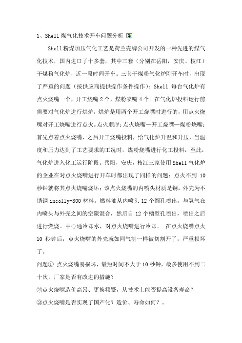
1、Shell煤气化技术开车问题分析Shell粉煤加压气化工艺是荷兰壳牌公司开发的一种先进的煤气化技术,国内进口了十多套,其中三套(分别在岳阳,安庆、枝江)干煤粉气化炉,近一段时间开车。
三套干煤粉气化炉刚开车时,出现了严重的问题(按供应商提供操作条件操作):Shell每台气化炉有点火烧嘴一个,开工烧嘴2个,煤粉喷嘴4个。
在气化炉投料运行前需要对气化炉进行烘炉,烘炉是用两个开工烧嘴时进行的,用点火烧嘴对开工烧嘴进行点火。
点火顺序:点火烧嘴—开工烧嘴—煤粉烧嘴;首先点着点火烧嘴,之后开工烧嘴投料,给气化炉升温和升压,当温度和压力达到了工艺要求的工况时,煤粉烧嘴进行化工投料,至此,气化炉进入化工运行阶段。
岳阳,安庆,枝江三家使用Shell气化炉的企业在对点火烧嘴进行开车时都出现了同样的问题:点火不到10秒钟就将其点火烧嘴烧坏;该点火烧嘴的内喷头材质是铜,外壳为不锈钢incolly-800材料。
燃料油从内喷头12个圆孔喷出,与氧气在内喷头与外壳之间的空隙混合,然后自12个槽型孔喷出,喷出之后进行燃烧。
中心通冷却水,对点火烧嘴进行冷却。
在点火烧嘴点火10秒钟后,点火烧嘴的外壳就如同气割一样被切割开了,严重损坏了。
问题①点火烧嘴易损坏,最短时间不大于10秒钟,最多使用不到二十次,厂家是否有改进的措施?②点火烧嘴造价高昂、更换频繁,从技术上能否提高设备寿命?③点火烧嘴是否实现了国产化?造价、寿命如何?。
2、SHELL气化炉、GE废锅气化炉和GE水冷激气化炉①气化炉运行负荷是否能够达到100%?,目前是多少?②连续运行时间是多少?目前有没有突破两个月?③维修项目有哪些?维修时间能否缩短?成本如何?3、煤气化工艺中循环使用的洗涤灰水如何处理效果最佳?4、壳牌煤气化工艺流程中的合成气反吹系统的反吹介质能否用洗涤后的粗合成气改为高温高压氮气?是否满足下游装置的工艺要求?对比节省工程投资是多少?5、壳牌粉煤气化是一种先进成熟的洁净煤气技术,该技术的关键设备是由气化炉、输气管和合成冷却器三大件组成,其中气化炉又是核心,如何将气化炉、输气管和合成气冷却器等设备进行安全可靠合理的配置,实现高转化效率,长周期运行,节省投资?6、废锅造价高,现在是否有降低造价的措施?尤其采用上行废锅形式,煤气激冷、余热回收、去除渣尘使这套系统变得庞大、复杂、昂贵;为了清除渣尘,采用庞大的陶瓷过滤装置,需要定期脉冲反吹。
77-302壳牌规范

ASME boiler and pressure vessel code, Section IX: Qualification standard for welding and brazing procedures, welders, brazers and welding and brazing procedures.MATERIALS, EXAMINATION AND CERTIFICATION REQUIREMENTS FOR VALVES IN GENERAL SERVICES 1).1. INTRODUCTION 1.1 SCOPEThis document contains requirements for materials, examination, repair and certification of valves in general services. This specification shall be read in conjunction with the requirements of the relevant material specifications (e.g. the ASTM specifications) and the MESC specifications for the particular types of valves.NOTES:1. General service valves are used in any PED fluid group 2 (gas and liquid) services,including steam, classified in PED conformity assessment categories SEP, I, II and III (ref. PED directives 97/23/EC, articles 9, 10, WPG guidelines 1/8, 1/15 and annex II). General services are services not classed as "special service" in MESC specification SPE 77/303.2. Special service valves are used in (dangerous/hazardous) PED fluid group 1 (gas andliquid) services classified in PED conformity assessment categories III and IV (ref. PED directives 97/23/EC, articles 9, 10, WPG guidelines 1/8, 1/15 and annex II). Safety accessories are classified in category IV.1.2Valve brands, types and styles shall be accepted by Shell Global Solutions International B.V. (Shell-GSI) and listed in the Shell-GSI Technical Accepted Manufacturers And Products (TAMAP) database.1.3Valves that are not yet accepted by Shell-GSI, and therefore not listed in theShell-GSI TAMAP database, shall be prototype tested in accordance with the relevant Shell-GSI requirements and specifications.1.4Foundries and forge masters shall be evaluated and qualified by the valve manufacturer. Shell-GSI may request audit reports and other evidence to ensure cast and forged materials are meeting our acceptance criteria.1.5Valve manufacturers and their sub suppliers shall have ISO 9000 series quality system certification. Valve manufacturers of ISO 14313 and API 6D valve standards shall be licensed to use the API monogram.2. REFERENCES 2.1.In this specification reference is made to the following publications:NOTE:Unless specifically designated by date, the latest edition of each publication shall be used, together with any amendments/supplements/revisions thereto.ISO 14313 API 6D Specification for pipeline valves (gate, ball and check valves) ASME B16.34 Valves, flanged, threaded and welding end.ASME Section IXASTM A 105Specification for forging, carbon steel, for piping components.ASTM A 182 Forged or rolled alloy-steel pipe flanges, forged fittings, valves and parts for high temperature service.ASTM A 216 Steel castings, carbon, suitable for fusion welding, hightemperature service.ASTM A 217 Steel castings, martensitic stainless and alloy, for pressurecontaining parts, suitable for high temperature service.ASTM A 262 Standard Practices for detecting susceptibility to intergranularattack in austenitic stainless steels.ASTM A 336 Specification for alloy steel forging for pressure and hightemperature parts.ASTM A 350 Specification for forging, carbon and low-alloy steel, requiring notch toughness testing for piping components.ASTM A 351 Specification for steel castings, austenitic, austenitic-ferritic(Duplex) for pressure containing parts.ASTM A 352 Steel castings, ferritic and martensitic, for pressure containingparts, suitable for low temperature service.ASTM A370 Standard test methods and definitions for mechanical testing ofsteel products.ASTM A 494 Specification for castings, nickel and nickel alloy.ASTM A 516 Specification for pressure vessel plates, carbon steel, formoderate-and lower temperature service.ASTM A 744 Standard specification for castings, iron-chromium-nickel, corrosion resistant for severe service.ASTM A 890 Specification for castings, iron-chromium-nickel-molybdenumcorrosion resistant, Duplex (austenitic-ferritic) for generalapplication.ASTM B 150 Specification for aluminium bronze rod, bar and shapes.ASTM G28 Standard test methods of detecting susceptibility tointergranular corrosion in wrought, nickel-rich, chromium-bearing alloys.EN 10204 Metallic products – types of inspection documents.ISO 148 Steel – Charpy impact test (V-notch).ISO 9000 Quality management system requirements.ISO 10474 Steel and steel products - inspection documents.ISO 14313 Petroleum and natural gas industries – Pipeline transportationsystems – Pipeline valves.MSS SP-55 Quality standard (visual method) for steel castings for valves,flanges and fittings and piping.NACE MR 0175 (Edition 2002)Standard material requirements; Metals for sulphide stress cracking and stress corrosion cracking resistance in sour oilfield environments.PED 97/23/EC Pressure Equipment Directive, 97/23/ECSTOOMWEZEN Rules for pressure vessels.3. MATERIALSREQUIREMENTS3.1 CHEMICALCOMPOSITION3.1.1 BasematerialsFor the materials mentioned below, the following restrictions in chemical compositionshall apply:Material grade Additional restrictionsASTM A105 Carbon content shall be 0.23% weightmaximum.Carbon equivalent (CE) shall be 0.43% weightmaximum.ASTM A516 grades 60 and 65ASTM A216 grade WCB Carbon content shall be 0.25% weight maximumASTM A350 grade LF2 class 1 and 2 Carbon equivalent (CE) shall be 0.43% weight maximum and shall be determined by the formula mentioned previously.ASTM A352 grade LCC Manganese content shall be 1.30% maximum ASTM A182 grades F316 UNSS316000.Carbon content shall be 0.03% weight maximumASTM A351-CF8M andASTM A351-CF3M(Ref. Note 1)Carbon content shall be 0.03% weight maximumASTM A182 grade F51; and Duplex stainless steel UNS S31803 Nitrogen content shall be 0.15% weight minimumASTM B 150 grade UNS C63200 Aluminium content shall be 8.50% weightminimum and 10% weight maximumThe carbon equivalent (CE) shall be determined by the formula as mentioned below:CE= C + Mn/6 + (Cr+Mo+V)/5 + (Ni+Cu)/153.2 HEATTREATMENT3.2.1 The Cr-Mo steels to ASTM A 182 grade F5a, F9, F11 class 2, ASTM A 182 grade F22class 3, ASTM A 217 grade WC6 and ASTM A 217 grade WC9 shall be furnished in thenormalised and tempered condition.3.2.2 Austenitic/ferritic(duplex) stainless steel UNS S31803UNS S31803 materials (including castings) shall be solution annealed between 1020ºCand 1100ºC, followed by rapid quench, after all forming operations.Repair welding of UNS S31803 castings shall be in accordance with the requirements ofASTM A744 Paragraph 10.3.2.3 Austenitic stainless steel forging to ASTM A182 and ASTM A336 andcasting to ASTM A351.All austenitic stainless steels shall be supplied in the solution heat treated condition.For non-stabilized grades with a carbon content larger than 0.03% solution annealingshall be repeated after any welding.3.2.4 Austenitic Steel Forgings to ASTM A182 grades F321 and F347If specified in the relevant MESC description a stabilising heat treatment shall beperformed between 900ºC and 950ºC for two hours, followed by cooling in still air. Thisshall be applied after the solution heat treatment and again after any welding.3.2.5 Nickel alloy castings to ASTM A494 grade N-7MNickel alloy castings to ASTM A494 grade N-7M shall be solution annealed at 1180 ºC+/- 10 ºC. Annealing at other temperatures can be accepted provided qualification testsshow that this leads to a fully solution annealed structure which is free of precipitates.Castings to ASTM A494 N-7M shall be post-weld heat treated following weld repairsusing the same solution annealing procedure as used earlier.3.2.6 Carbon steel and alloy 400:3.2.6.1 If welding is applied on valve parts made of Alloy 400, they shall be Post Weld HeatTreated (PWHT) at 590 ºC for at least 1 hour.3.2.6.2 All repair welds in carbon steel and Alloy-400 material shall be PWHT at 590 ºC for atleast 1 hour per 25 mm thickness, followed by X-ray re-examination.3.2.7 All heat treatment procedures shall be subject to statistical process control to ensure thatthe final material properties comply with the material standard and this specification. Theprocess control data and related periodic quality control checks shall be documented.3.3 HARDNESSIf wet H2S or sour service conditions are specified, the hardness requirements ofNACE MR 0175 Edition 2002 shall apply for any process-wetted part of the valve andpressure-retaining bolting.For all other (non-NACE MR 0175) services the maximum allowable hardness shall be:Base metal, welds and heat affected zones of pressure containing parts 248 HV10Base metal of internals with weld deposits or hard facings 400 HV1013% chromium steel internals 400 HV10Hardness indentations shall be avoided on any sealing or sliding surfaces.TESTING3.4 IMPACTImpact testing is required for:-Cr-Mo steels to ASTM A 182 grade F11 class 2, ASTM A 182 grade F22 class 3, ASTMA 217 grade WC6 and ASTM A 217 grade WC9 if the thickness of any section of thesematerials is greater than 50 mm.-Low temperature carbon steel to ASTM A352 grade LCC-Carbon manganese forging to ASTM A350 grade LF2, class 1-fine grained C-Mn steels to ASTM A 516 grades 60 and 65- Austenitic/ferritic duplex 22%Cr stainless steels to ASTM A351 grades CH10, CH 20and CE8MN and ASTM A 890 grade 4A and the 25 % Cr duplex stainless steels toASTM A890 grades 5A and 6A.- Martensitic stainless steel to ASTM A182-F6NM.For low temperature carbon steel valves the notched bar impact test shall be performed,in accordance with the applicable ASTM standard, at a temperature of minus 50degrees Celsius with an average energy value of 26 joules minimum for 2 and anyof 3 specimens and 22 joules minimum for the single specimen.Where welding is perfomed on austenitic stainless steel forgings to ASTM A182and castings to ASTM A351 as part of the valve assembly, having a minimumdesign temperature of <-29°C, welding procedures shall be qualified by impacttesting at the minimum design temperature specified in accordance with therequirements in ASME B31.3, section 323.22.In addition to these requirements as stated in API RP582 section 6.3.2, all weldsshall have a ferrite number for the weld material not exceeding 8FN.For all other materials the impact tests shall be performed on test pieces from the sameheat as the valve body and which have been simultaneously subjected to the same heattreatment.The test temperature shall be for:-Cr-Mo valves (thickness > 50 mm): +20ºC and-Duplex stainless steels: minus 50ºCThe test specimens of forged/wrought material shall be taken in the transversedirection at 1/4 and 1/2 of the thickness. Castings shall have one set of impacts takenfrom a test block of the same melt and heat treatment batch.For each section, three tests shall be performed and the resulting Charpy-V notchenergy impact values shall be for:-Cr-Mo steels: 55 joules average, 48 joules minimum for single specimen-Duplex stainless steels: 40 joules average, 31 joules minimum for single specimenNote: On the impact testing requirements of Cr-Mo and Duplex, these are additionalrequirements due to the fact that there are no limits set for these materials in the ASTMstandard and therefore no reference can be made to a specific ASTM standard.TESTING3.5 CORROSION3.5.1 For austenitic stainless steels (AISI 201, 202, 301, 304H, 316, 316H, 317, 317L, 321and 347) and austenitic/ferritic (duplex) stainless steels the statistical process control,mentioned in section 3.2.8, shall include inter granular corrosion testing in accordancewith ASTM A 262, Practice E.Tested specimens shall reveal no signs of inter-granular corrosion.3.5.2 For austenitic stainless steels (AISI 304, 304L, CF3, CF8) and UNS N08028 thestatistical process control, mentioned in section 3.2.8, shall include inter granularcorrosion testing in accordance with ASTM A 262, Practice C and shall result in anaverage corrosion rate of no more than 0.3 mm per annum.3.5.3 For wrought Nickel-Rich, Chromium-Bearing alloys (UNS N06007, N06022, N06030,N06059, N06200, N06455, N06600, N06625, N06686, N06985, N08020, N08367,N08800, N08825, N10276) the statistical process control, mentioned in section3.2.8, shall include inter granular corrosion testing in accordance with ASTM G28method A.3.5.4 For other materials (not listed in ASTM A 262 and ASTM G 28) where inter granularcorrosion could be of concern (e.g., cast nickel-rich, chromium-bearing alloys) thestatistical process control, mentioned in section 3.2.8, shall include inter granularcorrosion testing with a relevant test. The procedure and acceptance criteria shallbe submitted to the Principal for approval.4. NON-DESTRUCTIVE EXAMINATION (NDE)4.1 Regardless of the sampling specified in section 4.2.1, a prototype casting shall be (orshall have been) fully inspected and tested by the manufacturer in accordance with thespecified acceptance criteria. In addition to the NDE specified in table 1, the prototypecasting shall be (or shall have been) radio-graphed (Ref. 4.2.5 note 5) in accordance withASME B16.34 section 8, with 100% full coverage of the casting. Acceptance level shallbe based on the requirements of ASME B16.34 annex B.4.2 NDE extent (sampling), methods and acceptance criteria shall be in accordance with thevalve design code and sections 4.2 and 4.3 of this MESC additional requirement.4.2.1 The valves on an order shall be separated into inspection lots.For valves produced by the same manufacturer a different lot is applicable for each ofthe following:- valve type (gate, globe, check, etc.)- valve body basic material type (carbon steel, LTCS, ferritic alloy, austenitic alloy,non-ferrous alloy, ferritic ductile iron, non-ferrous alloy)- quantity per heat batch (produced by the foundry) or heat treatment batch,whatever gives the biggest lot size.Each inspection lot shall be further divided into categories A and B as specified below:ACategoryASME rating: classes 150, 300, 600 All sizesBCategoryASME rating: classes 800, 900,All sizes1500, 1500 special class & 25004.2.2 From each inspection lot, percentage samples shall be taken in accordance with table 1,with a minimum of one valve per lot (which shall be the largest valve in that lot).4.2.3 A lot shall be accepted if all the samples of the lot meet the specified acceptance criteria.4.2.4 If any of the samples fails to meet the acceptance criteria, additional samples equal tothe original number shall be inspected.If these samples meet the acceptance criteria, the lot shall be accepted with theexception of the initially rejected items. If any of the additionally inspected samples failsto meet the acceptance criteria, then 100% of the lot shall be inspected or, at theprincipal's discretion, the entire lot shall be rejected.4.2.5 A sampling and inspection scheme shall be submitted to the principal.Table 1 Initial sample percentages per categoryComponentmaterial:carbon steels ferritic alloys(note 1) austeniticalloysnon-ferrousalloysSample (%) per category (section 4.2.1)Category(section 4.2.1)A B A B A B A B Visualinspection(notes 2 and 3)100 100 100 100 100 100 100 100Forging(notes 2, 6, 7 and 8)UT(note12)0 1000 1000 1000 100 MT10 10 10 10 0 0 0 0 PT 0 0 0 0 10 10 10 10Casting(notes 2,6, 7 and 8)RT 0 10 0 10 0 10 0 10MT10 10 10 10 0 0 0 0PT 0 0 0 0 10 10 10 10Butt welds (notes 5, 6, 8, 11)RT(note 9)100 100 100 100 100 100 100 100MT(note13)10 10 100 1000 0 0 0PT(note13)0 0 0 0 10 10 100100Butt weld valveends of casting(notes 8, 9)RT 100 100 100 100 100 100 100 100Butt weld valve ends of forging (notes 6, 8 )MT 10 10 100 100 0 0 0 0PT 0 0 0 0 10 10 100 100Butt weld valveends of “fabricated” valves(notes 5, 6, 8, 11)RT (note 9)100 100 100 100 100 100 100 100MT (note 13)1010 100 100 0 0 0 0PT(note 13)0 0 0 0 10 10 100 100 Weld overlays(note 3)PT 10 10 10 10 10 10 10 10Hardness test(note 4)10 10 10 10 10 10 10 10 Positive Material Identification (note 10)PMI ApplicableNOTES:1. Including duplex stainless steel and martensitic stainless steel.2. Body, bonnet, cover, body adapter and screwed ball valves inserts.3. Closure members such as gate/wedge, disc, ball, plug, seat rings and seat pocket / stem seal area.4. If required by the applicable standard (e.g. ASTM, NACE MR 0175).5. UT in lieu of RT may be applied if the configuration precludes RT. The UT acceptance criteria shall comply with ASME B16.34 Annex E.6. PT shall be applied if MT is not feasible or when the work efficiency and detection rate of defects is better.7. PT may be applied instead of MT for: - seat rings;- duplex stainless steel materials; - butt-welding ends.8. RT = radiographic examination; MT = magnetic particle examination PT = liquid penetrant examination; UT =ultrasonic examination.9. For all butt welds in cast and fabricated valve bodies including butt weld end preparations, with exception of those made by friction welds. For welded bonnet gate and globe check valves, DN 50 and smaller (designed toAPI 600, API 602, ISO15761) RT is 1% of the lot with a minimum of 1 valve.10. For CS valves as per manufacturer’s standard practice for materials having a P-number of 3 or more (ref. ASME section IX), i.e. alloy steel valves: PMI = 100% for forged & cast pressure retaining components, weld constructions and welding ends (if applicable).PMI = 10% for closure members in valves in nominal sizes DN 40 and smaller.11. For valves with welded on flanged ends and /or welded on bonnets (flanges).12. Only applicable in case of:- valve body and bonnet wall thickness over 100 mm, - end flange thickness over 100 mm, - adaptor flange thickness over 100 mm, - cover flange thickness over 100 mm.13. Weld surface after welding and weld bevel preparation prior to welding.4.3 NDE METHODS AND ACCEPTANCE CRITERIA4.3.1 Visual examination of castings shall be in accordance with MSS SP-55. Visual surfaceexamination of forging shall be in accordance with ASME B16.34 section 8.3.2.2.4.3.2 RT shall comply with ASME B16.34 section 8.3.1.1 (casting) and 8.3.2.1 (forging).UT shall comply with ASME B16.34 section 8.3.1.3 (casting) and 8.3.2.1 (forging).MT shall comply with ASME B16.34 section 8.3.1.2 (casting), 8.3.2.2 (forging) andAnnex C andPT shall comply with ASME B16.34 section 8.3.1.2 (casting), 8.3.2.2 (forging) andAnnex D.4.3.3 Exterior and accessible interior surfaces shall be examined (MP and PT) in the finalmachined condition.4.4 REPAIRDefect removal and repair shall be in accordance with ASME B16.34 section 8.All repairs to duplex stainless steel castings (UNS 31803) require liquid penetrant testingafter excavation of the defect and on completion of repair welding.5. CERTIFICATION AND TRACEABILITY5.1 GENERAL5.1.1 Documentary evidence shall be included in the technical dossier. The manufacturershall store this dossier for at least 10 years. The applicable type of inspectiondocuments shall be as specified in the purchase order.5.1.2 All certificates shall be originals or certified copies.5.1.3 The certificates shall be in the English language or in other languages if they areaccompanied by an endorsed and dated English translation of the contents.5.1.4 Certificates for components shall include certification of the base materials if physicaland mechanical properties of the components differ from those of the base materials. 5.1.5 In case a component is supplied by a processor, or an intermediary, and the componentmaterial deviates from base material, the certificate shall consist of two documentscovering both parts of the manufacturing process, and shall comply with ISO 10474. 5.1.6 The level of certification for both the base materials and the components shall be equal.5.1.7 The manufacturer shall implement a materials tracking system to ensure the correctmaterials are used. The manufacturer shall implement a materials traceability system toensure that materials requiring type 3.1.B certificates are fully traceable to theircertificates.DOCUMENTS5.2 INSPECTION5.2.1 The manufacturer shall be able provide:- inspection certificates in accordance with ISO 10474 type 3.1.B orEN 10204, type 3.1.B ,- test reports in accordance with ISO 10474 type 2.2 or EN 10204, type 2.2 or- certificate of compliance to ISO 10474 type 2.1, as defined in table 2.Table 2 Inspection certificates and test reportsComponent EN 10204 or ISO10474 certificate ortest reportMain pressure bearing parts in PED category I: e.g. body, bonnet, body (screwed) insert, cover, adapter and pressure retaining plugs / bleed connections (flanges)2.2 (note 4)Main pressure bearing parts in PED categories II, III & IV: e.g. body, bonnet, body (screwed) insert, cover, trunnion (in case it is part of the body) adapter and pressure retaining plugs / bleed connections (flanges)3.1.B (notes 2 and 4)Pressure controlling parts: e.g. closure members (gate/wedge, disc, ball, plug and seat rings,2.2 (see note 1)Stem and trunnion 2.2(see note 1)Non pressure bearing parts and sealing components (gaskets,packing, “O”- rings)2.1Hingepin 2.2 Bellows,springs 2.2 Stuffing box follower and gland flange 2.2Bolting (i.e. studs, bolts, screws, nuts). 2.2(notes 1 and 3) Examination (NDE), pressure testing and fugitive emission testing 3.1.B Finished valve in compliance with the specifications 3.1.BNOTES:1. For end users in European member states and countries in the European Free TradeAssociation (EFTA) traceability is sufficiently covered by the PED through Annex I, section3.1.5, Guideline 7/5, note 6.3.For other end users batch traceability is accepted provided the manufacturers documentedbatch traceability procedures guarantee that certification of parts without identification marks are fully traceable to a specific heat or heat treatment lot.2. Ref.: PED guidelines 7/5 and 7/16. Provided the manufacturer has an ISO 9000 series qualitymanagement system certified by a competent notified body and having undergone a specific assesment for materials.3. Ref.: PED guideline 7/8. Bolting is not considered to be main pressure bearing parts unless itsfailure would result in a sudden discharge of pressure. When bolting is used as main pressure bearing parts they shall be certified similar.4. Ref. PED guideline 7/6. Main pressure bearing parts are parts that constitute the pressureenvelope and are essential for the integrity of the equipment.5. Contents of documents:compliance shall state:ofCertificate2.1The manufacturer certifies that the products supplied comply with therequirements of the purchase order, without mention of any test results.The certificate of compliance is a document drawn up on the basis of non-specific inspection and testing.2.2 Test reports shall state:-test results, based on non-specific inspection and testing, specified in thepurchase order;-Principal’s purchase order number;-applicable material standards;-corresponding materials/items including relevant identification markings;-compliance with the specified requirements.3.1.B inspection certificates shall include:-test results, based on specific inspection and testing, specified in the purchaseorder,-manufacturer’s order number;-certificate identification number and date of issue;-a fully detailed material specification;-charge, batch or heat numbers;-both specified and actual mechanical properties and chemical compositions;-N.D.E. methods and results (when applicable);-Positive Material Identification (PMI) test results for materials having a P-number of 3 or more, as defined in ASME section IX;-results of hardness tests (when applicable);-results of impact tests (when applicable);-reference to heat treatment procedure, furnace charge number and heattreatment records (when applicable).6. DOCUMENTATION6.1 The valve manufacturer shall be able to provide documentation, which shall be availableprior to shipment. Computerised data or photo-copies of originals (verified and signed bythe QA/QC-department) may be provided instead of originals.The documentation shall include the following:-purchase order and identification of the valves by serial number or manufacturer's code.-materials test reports and inspection certificates as specified.-NDE reports, including sketches, if necessary, showing the locations of examination.Radiographs shall be retained by the manufacturer for at least five years.-listing of applicable and authorised concessions, waivers and/or material substitutions.-manufacturer's statement of compliance signed by an authorised representative.-all other requirements when valves are supplied with CE mark.-listing of applicable manuals (e.g. assembly/maintenance manuals).7. WITNESSING BY THE PRINCIPAL7.1 The principal shall specify if, and to what extent, he (or his representative) will witnessthe manufacturer's inspections and tests and/or will perform a document review beforeshipment.。
《流化催化裂化手册》第三版整理重译第一章
整理者前言长期以来,《流化催化裂化手册》都是广大催化剂裂化以及炼油石化从业者尤其是像我这样入门级小学生学习催化裂化工艺专业知识的启蒙读物。
现在其最新的第四版英文原版已经于上月发行。
因此最近利用空闲时间重新整理了本书第三版中译本的第一章工艺概述部分。
此部分做为催化裂化工艺的概述,作者用有限的篇幅简要而又细致地说明了整个催化裂化装置的全部流程和工艺要点,非常适合作为学习相关知识的入门读物。
重新整理的过程主要对原有译本中部分容易引起误解和不甚通顺的地方进行了重新翻译同时统一了部分前后不统一的专业名词,部分词汇翻译改用了国内业界常用的说法,另外补充了英文原版中的作者介绍。
当然,以我的水平,完全是班门弄斧,关门耍刀,发出来也就是给大家图一乐,找几个茬,望真有看的人轻拍。
纯属个人爱好,勿做商业用途。
本身我就擦边了。
当然要在此感谢给我提供过第二版和第三版的学习资料的某位行业大牛级专家原译者前言自中国第一套流化催化裂化装置于1965年实现工业化以来,催化裂化工艺作为炼油行业的主要加工工艺,发展极为迅速。
50多年来,中国催化裂化装置从无到有,技术水平不断提高,装置规模和加工能力不断扩大,在流化催化裂化技术领域积累了丰富的经验,取得了巨大的成就,有些技术已达到国际先进水平。
(Fluid Catalytic Cracking Handbook(3rd Edition)》是由Elsevier出版集团于2012年出版的一本新书,该书在2000年岀版的第二版基础上増加了一些新的章节,并对原有的章节也进行了全面更新。
本书全面介绍了催化裂化工艺、工艺控制设施、原料及产品、催化剂及添加剂、化学反应、装置监控与故障排除、项目执行与管理、耐火衬里系统、设备工艺和机械设计、装置优化与消除瓶颈、污染物排放以及渣油和深度加工处理原料的加工等方面的内容,是流化催化裂化技术领域非常实用的一本工具书。
由《石油炼制与化工》编辑部翻译、中国石化出版社2002年出版的《Fluid Catalytic Cracking Handbook(2nd Edition)》中文版,为本书一些章节的翻译提供了很好的借鉴,在此表示感谢。
加氢反应器简介ppt课件

反应器细部结构的改进
* 裙座结构的改进
LPEC @ 2004 中 国 石 化 集 团 洛 阳 石 油 化 工 工 程公 司
反应器细部结构的改进
* 增设热箱
LPEC @ 2004 中国石化集团洛阳石油化工工程公司
反应器内件型式及作用
反应器内件设计性能的优劣将与催化剂性 能一道体现出所采用加氢工艺的先进性。
加氢反应器使用中的保护
开停工时必须严格执行操作手册的要求。为防止形 成较大的热应力,推荐开工和停工时的升温和降温 速度分别不要超过25℃~30℃/h和25℃/h。
要尽量避免非计划性的开停工。这对保护反应器和 减轻其堆焊层的氢致剥离都是有效的。
当反应器安装或停工检验而打开顶部人孔时,一定 要设置合适的防护措施,防止雨水飘入器内。
箱 起冷却作用的冷氢充分混合,
收;
而又将具有均匀温度的气液 混合物再均匀分配到下部的 催化剂床层上。
冷氢盘和喷射盘的安装水 平度,包括制造公差、荷载 作用下的挠度等在内,可按
±6mm控制。再分配盘的
要求与气液分配盘同。
T
急冷氢 急冷氢 急冷氢
T出
T入
第一床层 第二床层 第三床层 第四床层
加氢装
置反应过
3.
更换这种分配盘后,床层径向温差不到
5℃,催化剂相对活性提高了250%。这些都
表明要最大化利用高活性催化剂的性能,需要
有好的反应器内构件。
国内外加氢反应器内构件技术的发展
1.
TOPSOE公司的反应器内构件技术
2. Topsoe公司又开发出汽举式(Vapor-Lift)
分配盘
3.
分配器间距越小,滴点数越多,预示着液体
加氢反应器大型化
- 1、下载文档前请自行甄别文档内容的完整性,平台不提供额外的编辑、内容补充、找答案等附加服务。
- 2、"仅部分预览"的文档,不可在线预览部分如存在完整性等问题,可反馈申请退款(可完整预览的文档不适用该条件!)。
- 3、如文档侵犯您的权益,请联系客服反馈,我们会尽快为您处理(人工客服工作时间:9:00-18:30)。
壳牌供应商原则
在壳牌一般商业原则和集团行为准则指导下,我们将与符合以下标准的供应商和承包商开展合作:致力于可持续发展,并且勇于承担经济、环境和社会发展责任。
壳牌将进一步发展并加强同供应商和承包商的合作,只要供应商和承包商承诺遵守以下原则或其他类似标准,并以该等原则和标准规范自身的业务行为并管理各自的承包商和分包商。
承包商和供应商应建立健全的举报制度,方便员工在遇到以下问题时以匿名形式举报。
1. 商业信誉
承包商和供应商应遵循所有相关的法律法规。
承包商和供应商不可以参与贿赂、腐败或任何其他的不道德行为,也不可以知情不报。
承包商和供应商支持公平竞争。
避免利益冲突。
2. 健康、安全和环境
承包商和供应商应建立全套的健康、安全和环境(HSSE)管理体系,以确保在遵守所有相关法律法规的情况下实现持续的绩效改进。
承包商和供应商:
承诺通过遵守所有适用的环境法律法规对环境予以保护。
有效地使用能源和自然资源。
致力于减少因经营、产品和服务产生的浪费、气体排放和废弃物排放。
3. 社会绩效
承包商和供应商应尊重友邻,为当地的社区发展做出自己的贡献。
4. 劳动和人权
承包商和供应商应遵守联合国人权宣言和国际劳工组织 (ILO) 核心公约中有关人权的规定,并在此规范下开展工作。
承包商和供应商:
不得使用童工。
不得使用受强迫、监禁或强制的工人工作。
遵循所有与结社、集体谈判自由相关的法律和法规。
不应纵容歧视、骚扰或报复,应提供安全、健康的工作环境。
所提供的工资和福利应达到或超过国家法定标准,并应遵守与工作时间相关的所有法律和法规。
© Shell Global Solutions International BV 2011.
如果希望复制本文件的任何部分,应征得 Shell Global Solutions International BV 的许可。
如果来源得到认可,通常会给出许可。
如果。