电子潜水泵漏电断路器使用说明
德力西 DZ47sLES小型漏电保护断路器使用说明书
DZ47sLES RESIDUAL CURRENT OPERATEDCIRCUIT-BREAKER NAVIGATORSeries User ManualPlease carefully read this User Manual before installing and operating the product, and keep this manual properly for futurereferenceSafety NoticePlease carefully read this manual before the installation, operation, run, maintenance, and inspection of the product, and install and operate this product properly according to the contents of the instructions.Danger:⚫It is prohibited to operate the circuit breaker with your wet hands;⚫It is prohibited to touch the conductive part during operation;⚫Make sure that the product is de-electrified during the maintenance and service;⚫It is prohibited to use the short circuit method to test the product;Caution:⚫The installation, maintenance, and service shall be carried out by the qualified professionals;⚫All characteristics of the product have been set in the factory, and the product cannot be disassembled without permission or adjusted at will during operation;⚫Please confirm that the product voltage, rated current, frequency, and characteristics of the product meet the working requirements before use;⚫Connect the wire according to the wiring mark on the product (the load end is the outlet terminal); tighten the wiring screw when the wire is inserted into the wiring hole, and fasten the wire until it cannot be loose or pulled out; the exposed copper wire head shall not be exposed outside the terminal block;⚫This product cannot provide the protection for electric shock caused by contact with two wires of the protected circuit simultaneously;⚫This product has an IP20 protection level without dustproof protection. Therefore, when used in a dusty place, it shall be installed in a well-sealed terminal box;⚫When there is voltage on the power supply side, the circuit board of the product is in the working state after power-on and here is a certain temperature on the side, and this belongs to the normal phenomenon;⚫This product is not suitable for some special applications such as frequent motor starting, electric heating equipment, capacitor cabinets, high inductive and high capacitive loads and high temperature environments;⚫If found damage or heard abnormal sound when unpacking the product, please stop the operation immediately and contact the supplier;Table of Contents1 Main Purpose and Scope of Application…………………………............................................................................2 Product Model and Its Meanings (1)2.1 Product Model and Its Meanings................................................................... .. (1)2.2 Panel Introduction (2)3 Normal Working Conditions and Installation Conditions (2)4 Technical Characteristics................................................................... (3)4.1 Classification (3)4.2 Main Technical Parameters (3)4.3 Main Technical Performances (4)5 Outline and Installation Dimensions (4)6 Installation, Operation and Maintenance............................................. .. (5)7 Troubleshooting............................................. . (6)8 Unpacking Inspection............................................. . (7)9 Company’s commitments............................................. . (7)1 Main Purpose and Scope of ApplicationDZ47sLES series residual current operated circuit breaker (hereinafter referred to as leakage circuit breaker) has electric leakage (electric shock), overload, and short circuit protection functions, and can also have over-voltage and under-voltage protection functions according to the needs of users.DZ47sLES leakage circuit breaker is used in the AC 50/60Hz lines with rated voltage 230V/400V and rated current up to 63A for indirect contact protection of people, as well as overcurrent protection for buildings and similar lines. It can also provide protection against fires caused by persistent earth faults due to the non-operation of the overcurrent protection device. Leakage circuit breakers with overvoltage protection can also provide the production against excessive voltage increases due to grid faults.This series of products has been increasingly used in low-voltage power distribution systems as a backup protection against earth faults, direct contact and indirect contact electric shocks.The circuit breaker is equipped with 6 different accessories, including: OF auxiliary contact, MX+OF shunt releases, SD alarm contact, MV overvoltage release, MN undervoltage release and MVMN overvoltage and undervoltage release. When there are multiple accessories installed, the size for maximum number of installations is less than 54mm.2 Product Model and Its Meanings2.1 Product Model and Its MeaningsAccessory code: By default: Common type; G: Overvoltage typeDerived code: Electronic leakage circuit breakerProduct series numberDesign No.Product code2.2 Panel IntroductionPress beforepower-onPress once a monthLoad endLegends:1 Inlet terminal2 Company Logo3 Product model (overvoltage model DZ47sLES G)4 Trip curve and rated current (see Table 1)5 Rated voltage (see Table 1)6 Breaking capacity and frequency (see Table 1)7 Reference standards8 Certification marks9 Identification on load end 10 N-pole marking 11 Reset button12. Rated residual making and breaking capacity, rated residual operating current, rated operating time, (overvoltage protection parameter is Uvo= (280±5%)V)13 Wiring diagram 14 Test button 15 Outline terminal3 Normal Working Conditions and Installation Conditionsa) Ambient air temperature:The upper limit of the ambient air temperature does not exceed +70°C, the lower limit does not below -35°C, and the mean temperature does not exceed +35°C within 24 hours; note: If the residual current operated circuit breaker is used in places where the ambient air temperature is higher than +70°C or below -35°C, please contact the manufacturer;b) AltitudeThe altitude of the installation site does not exceed 2000m;c) Atmospheric conditions:When the temperature is +60°C, the relative humidity of the air does not exceed 50%; a higher relative humidity is allowed at lower temperatures; for example, when the temperature is +20°C, the relative humidity does not exceed 90%. Special protection measures should be taken for condensation occurred occasionally due to temperature changes;d) Installation conditions:The external magnetic field near the installation site of the residual current operated circuit breaker should not exceed 5 times of the geomagnetic magnetic field in any direction; the installation position should be vertical, and the inclination angle in any direction should not exceed 10°; the product is installed in a place where there is no shock vibration and no rain or snow erosion; the standard TH35-7.5 steel installation rails are used for installation;e)Pollution degree: Level 2;f)Installation category: Class II, Class III;g)Protection grade: IP20 (Installed a power distribution tank, distribution cabinet or box: IP40);h)For product with a N pole, please connect the zero line to the pole marked with N when wiring.i)Normal storage and transport conditionsa)Temperature: -40°C~ +85°C;b)Relative humidity (at 25°C): ≤95%;c)Please handle the product gently during transportation, do not upside it down, and avoid strong collisions.4 Technical Characteristics4.1 Classificationa) According to the type of trip: Type B, type C, type D;b) According to the number of poles of the product: 1P+N, 2P (with and overcurrent protection pole), 3P, 3P+N, 4P;c) According to the rated current: 6A, 10A, 16A, 20A, 25A, 32A, 40A, 50A, 63A;d) According to the characteristics of leakage action: 10mA, 30mA, 50mA, 75mA, 100mA, 300mA.4.2 Main Technical Parameters4.3 Main Technical Performancea) Overcurrent release protection characteristics see Table 2b) Mechanical and electrical life1. Mechanical life: 20,000 times;2. Electrical life: 10,000 times.c) The protection characteristic curves of the circuit breaker are illustrated in Fig. 1.Fig. 1 B type thermal / electromagnetic trip characteristicscurveFig. 2 C type thermal /electromagnetic trip characteristicscurveFig. 3 D type thermal /electromagnetic trip characteristicscurve5 Outline and Installation DimensionsThe outline and installation dimensions are illustrated in Fig. 1.Fig. 1 Outline and installation dimensions6 Installation, Operation and Maintenancea)Check whether the product mark is consistent with the conditions used before installation;b)Correctly connect the wires at the inlet terminal and outlet terminal according to the product identification (the load current should be less than the rated current of the product);c)The N pole shall be connected correctly, and must be reliably wired, otherwise the product will not work normally;d)When installation, insert the residual current operated circuit breaker into the mounting rail until the residual current operated circuit breaker is fixed on it without looseness and fall-off. To dismantle the residual current operated circuit breaker, pull out the stopper.e)The rated tightening torque is 2.0N.m;f)The cross-sectional area of the connecting wire sees Table 3;Table 3 Sectional-area and rated current of the connecting (copper) wireRated current A 6 10 16, 20 25 32 40, 50 63Sectional area of wire mm 2 1 1.5 2.5 4 6 1016g) After power-on, operate the residual current operated circuit breaker test button several times and confirm whether it works reliably;h) The working reference temperature of the residual current operated circuit breaker is +30+50℃. When the ambient temperature changes, its rated value shall be corrected, and the temperature correction coefficient is listed in Table 4; if multiple residual current operated circuit breakers are installed in the same closed box, the temperature in the box will be increased accordingly, and the rated current should be multiplied by derating coefficient 0.8.7 Table 4 Rated current temperature correction coefficient tableTemp.Rated current (A)j) MaintenanceAfter the residual current operated circuit breaker is running for some time, it shall be checked regularly (monthly). After the circuit breaker is powered on and energized, press the test button and check the residual current operated circuit breaker can work reliably. If failure to work normally, please replace it immediately and do not operate it continuously.7 TroubleshootingThe faults and troubleshooting of the residual current operated circuit breaker see Table 5.Table 5 Fault and troubleshootingFault Cause SolutionM i s -o p e r a t i o nMis-operation caused by zero line earthed at the load side of the residual current operated circuit breaker When the zero line on the load side of the residual current operated circuit breaker is earthed, the normal operating current will flow in through the earth point to cause mis-operation.Residual current operated circuit breakerIncorrect wiringConnect the earth wire to the zero line at the power side of the residual currentoperated circuit breakerResidual current operated circuit breakerCorrect wiring Mis-operation bythe leakage current and the current ofthe wire tocapacitorWire on the load side is laid tightly on theground too longSelect the residual current operated circuit breaker with a large residual operating current The leakage current of the wire on the loadside to earth is increased due to insulationreduction.Replace wire8 Unpacking InspectionAfter unpacking, the user must check whether the product is intact, whether the exposed metal is rusty, and whether the product is defects due to poor transportation or storage. If found the above phenomenon, please stop the product, and contact the supplier timely for solution.9 Company’ commitmentThe free repair or replacement will be provided by the company for damage or abnormal operation of the product produced by our company due to poor manufacturing quality within 36 months from the date of the production under the premise that the user conforms to the operation and storage conditions and that the product is well sealed.A paid repair is provided when the warranty period expires. However, the paid repair is provided for damage caused by one of the following situations even within the warranty period:a)Improper operation, maintenance, or storage;b)Modification without permission, or improper maintenance;c)Damage caused by falling off after purchase or occurred during the installation process;d)Irresistible nature disasters such as earthquakes, fires, lightning strikes, and abnormal voltages.If you have any questions, please contact the dealer or the company’s customer service department.Customer service hotline: 400-826-8008Page 7CertificateDELIXI ELECTRIC LTDDELIXI ELECTRIC LTDDelixi Industrial Park, Liushi Town, Yueqing City, Zhejiang Province P/C.: 325604 Tel: (86-577)6177 8888Fax: (86-577)6177 8000Customer service hotline: 400-826-8008The first edition of this User Manual was issued in Nov. 2021.。
潜水泵安全使用操作
潜水泵安全使用操作
①电泵的开关箱必须装有漏电保护开关才准使用。
②用泵之前,要检查电源电压是否相符正常。
③潜水泵放下水工作之前,要认真检查引出电缆线有否破损,磕伤等痕迹,如有则立即更换或修理,用兆欧表检查电机对地绝缘电阻不得小于一兆欧才能使用。
④接上电源,起动电泵,检查空载及转向的情况,空转时间不得超过一分钟,否则容易烧坏密封。
⑤投入使用后,如出现漏电保护开关动作,应停止使用,排除故障,修好绝缘后方可使用。
⑥电泵工作时,如抽出的液体越来越少,可能是电泵堵塞,应先停电后,才能拉起电泵,挖出杂物,拉电泵时要用绳子绑在电泵的把手上拉起,切勿用电缆线吊放水泵。
⑦电泵不得露出水面外工作,更不能长时间脱水运行,以免电机发热, 烧坏定子绕组。
⑧水泵在工作时,不得用手抽提水泵和拉整电缆,操作人员更不能下
到水中,在水泵附近操作。
谨防触电事故发生。
⑨潜水泵抽完沉降池灰渣立即拉出池面用清水冲洗干净并放置好。
潜水排污泵使用说明书
潜水排污泵、给水泵安装、使用、维护说明书前言为保证设备正常运行和人身安全,在安装运行前应认真阅读本说明书。
本设备应由技术熟练的人员进行安装和操作运行,制造厂不承担由非专业人员参与而发生事故和责任。
如疑问,请即与本公司驻当地办事处联系。
一、主要用途和使用范围WQ、QXG、AS、AV系列潜水排污泵、潜水给水泵采用了国外多项先进技术,结构紧凑,使用维护方便。
其大通道水力部件设计和抗堵塞撕裂机构使水泵具有优良的过流性能,较高的工作可靠性,有利于实现自动化。
它广泛应用于市政工程、工业、商业、医院、宾馆、住宅区的污水排放,也适用于采油、农田灌溉等。
产品执行JB/T5118-2001《污水污物潜水电泵》标准。
使用条件:●输送介质最高温度应不超过40°C;●输送介质PH值为4~10;●输送介质中的固相物的容积比在2%以下;●输送介质的运动粘度为7╳10-7~23╳10-6m2/s;●输送介质介质密度应小于1.2╳103kg/m3;●可通过固体颗粒直径:φ25~φ180;●最大潜水深度:10m;●每二次启动间隔时间不小于10分钟。
二、系统说明WQ、AV、AS系列产品由潜水排污(给水)泵、控制设备、安装系统三大部分组成。
1、潜水排污(给水)泵:由电机和泵头组成,泵头与电机同轴,采用串联式机械密封。
其中电机防护等级为IP68,绝缘等级为F级;泵头由涡壳、叶轮、底盖等部件组成。
根据需要在潜水排污(给水)泵内设置有油室泄漏报警、电机绕组过热保护等功能。
2、控制设备:是潜水排污泵的启动、停止和运行监视系统。
根据用户要求不同可配置控制柜、端子箱、液位控制器等,并设有过载、缺相、短路、漏水、电机绕组超温等保护功能。
详见控制设备的随机文件。
3、安装系统:根据工况条件不同,安装方式有固定湿式安装、固定干式安装、移动式安装。
三、特点●独特的电缆密封设计-水密电缆,排除了电缆进水的隐患;●完美的电机冷却设计-水套冷却系统,通过高低压水管实行自流循环冷却(中型泵);●转子和叶轮进行动平衡检测,确保运行平稳。
德力西 CDB6LESi小型漏电保护断路器 使用说明书

CDB6LESiUser Manual □Please read the product instructions carefully before the installation and operation of the product, and keep those instructions properly for reference later.Safety NoticePlease carefully read this manual before the installation, operation, run, maintenance, and inspection of the product, and install and operate this product properly according to the product instructions.Danger:●It is prohibited to operate the circuit breaker with your wet hands;●It is prohibited to touch the conductive part during operation;●Make sure that the product is de-electrified during the maintenance and repair;●It is prohibited to use the short circuit method to test the product.Caution●The installation, maintenance, and repair shall be carried out by the qualified professionals;●The characteristics of the product have been set in the factory, and the product cannot be disassembled or adjusted at will during operation;●Confirm that the product operating voltage, rated current, frequency and use characteristics of the product meet the requirements before use;●Install and connect the wire according to the wiring mark on the product (load end is the wire outlet end), tighten the wiring screw after the wire is inserted into the wiring hole, and tighten the wire until it is not loose and pulled out; the exposed ends of the copper wire cannot be exposed out of the terminal block;●This product cannot provide the protection against the electric shock risk caused by touching two wires of the protected circuit simultaneously;●With the protection grade IP20, this product has no dustproof function. Please install the product in the well-sealed terminal box in the dusty application;●When there is voltage on the power supply side, the circuit board in the product is in working state after closing, and there is a constant temperature on the side, which is a normal phenomenon:●This product is not suitable for special occasions such as frequent motor starting, electric heating equipment, capacitor cabinets, high inductance or high capacitive loads and high temperature environments;●If found any damage or abnormal sound when unpacking, please stop the product and contact the supplier;Table of Contents1. Main Purposes and Scope of A pplication (1)2. Product Model and Meanings....................................................................... .. (1)3. Normal Use, Installation and Transportation C onditions (1)4. Technical C haracteristics…………………………………………………………………. ..................................... .24.1 Classification (2)4.2 Main Technical Performance P arameters................................................ .................................... (2)5. Outline and Installation D imensions (3)6. Installation and Use (M aintenance) ……………………………………………………. ........................................ .47. Troubleshooting…………………………………………………………………………........................................ .58. Unpacking Inspection............................................................................. (5)9 Company’s Commitments........................................................................ (6)1. Main Purposes and Scope of ApplicationCDB6LESi series residual current circuit breaker (hereinafter referred to as residual current circuit breaker) has electric leakage (electric shock), overload, and short circuit protection functions, and the overvoltage and undervoltage protection functions can also be added according to the needs of users.CDB6LESi residual current circuit breaker is used in the AC 50Hz/60Hz lines with rated voltage 230V/400V and rated current to 63A and below for indirect contact protection of people and for overcurrent protection of buildings and similar purposes. It can also provide protection against fires caused by persistent earth faults due to the non-operation of the overcurrent protection device. Residual current circuit breakers with overvoltage protection also provide the protection against excessive voltage increases due to power grid faults.This series of products has been increasingly used in low-voltage power distribution systems as a backup protection against earth faults and direct and indirect contact electric shocks.The circuit breaker has 6 different accessories, including: OF aux. contacts, MX+OF shunt release, SD alarm contacts, MV overvoltage releases, MN undervoltage releases and MVMN overvoltage and undervoltage releases. When there are multiple accessories installed, the size for the maximum number of installations is less than 54mm.2. Product Model and Meanings2.1 Product Model and MeaningAdditional code: By default: Common type; G: Overvoltage typeDerived codeElectronic residual current circuit breakerProduct design numberEnterprise code (Delixi)2.2 Panel IntroductionPress beforepower onPress monthlyLoad endLegends:1. Wire inlet 2 Company logo 3 Trip curve and rated current (see Table 1) 4 ON/OFF indicator window5 Product specification rated voltage (see Table 1) 6. Product model (overvoltage model is CDB6LESi G)7. Certification mark reference standard 8 ON/OFF handle 9 ON/OFF mark 10 Load end mark and wire outlet 11 N pole mark 12 Reset button 13 Rated frequency 14 Rated voltage, breaking capacity (see Table 1), rated residual marking and breaking capacity 15 Compliance standard, rated residual operating current16 Rated operation time (overvoltage protection parameters is Uvo = (280±5%)V)17 Wiring diagram 18. Test button3. Normal Use, Installation and Transportation Conditionsa) Ambient air temperature:The upper limit of ambient air temperature shall not exceed +70℃, the lower limit is not below -35℃, and the mean temperature within 24h does not exceed +35℃; note: When the residual current operated circuit breaker is used when the ambient air temperature is higher than +70℃ or below -35℃, please contact the manufacturer;b) Altitude:The altitude of the installation site does not exceed 2000m;c) Atmospheric conditions:At a temperature of +60℃, the relative humidity of the air does not exceed 50%; high relative humidity is allowed at lower temperatures, for example, when the temperature is +20℃, the relative humidity does not exceed 90%. Special protective measures should be taken for condensation occasionally generated due to temperature changes;d) Installation conditions: The external magnetic field near the installation site of the residual current operated circuit breaker should not exceed 5 times of the geomagnetic field in any direction; the installation position should be vertical, and the inclination in any direction should not exceed 10°; installed in a place without shock vibration and rain and snow attacks; the standard TH35-7.5 steel mounting rail is used;e) Pollution degree: Level 2;f) Installation category: Class II, Class III:g) Protection grade: IP20 (IP40: installed in power distribution tank, power distribution cabinet or box);h) For products with N pole, the zero line must be connected to the pole marked with N when wiring connection.i) Normal storage and transport conditionsa) Temperature: -40℃~ +85℃;b) Relative humidity (at 25℃): ≤95%;c) The product should be handled gently, cannot upside down, and avoid strong collision when transportation.4. Technical Characteristics4.1 Classificationa) According to the type of trip: Type B, Type C, Type D;b) according to the number of poles of the product: 1P+N, 2P (with an overcurrent protection pole), 3P, 3P+N, 4P;c) According to the rated current: 6A, 10A, 16A, 20A, 25A, 32A, 40A, 50A, 63A;d) According to the characteristics of residual current action: 10mA, 30mA, 50mA, 75mA, 100mA, 300mA.4.2 Main Technical Parametersa) The main technical parameters are listed in Table 175, 100, 300) mA; breaking time at I△n: (0.13~0.5) s.4.3 Main Technical Parametersa) The protection characteristics of the overcurrent release are listed in Table below:1. Mechanical life: 20000 times:2. Electrical life: 10000 times.c) The protection characteristic curves of the circuit breaker are illustrated in Fig. 1Fig. 1 B type thermal/electromagnetic trip characteristic curveFig. 2 C typethermal/electromagnetic tripcharacteristic curveFig. 3 D typethermal/electromagnetic tripcharacteristic curve5. Outline and Installation DimensionsThe outline and installation dimensions are illustrated in Fig. 1Fig. 1 Outline and installation dimensions6. Installation and Use, Maintenancea) Check whether the product mark is consistent with the working conditions before installation:b) Correct the wire at the inlet and outlet ends according to the product identification (the load current should be less than the rated current of the product);c) The N pole cannot be connected incorrectly and must be reliably wired, otherwise the produc t will not work normally;d) When installation, the residual current operated circuit breaker is inserted into the mounting rail, so that the residual current operated circuit breaker is fixed on it without looseness and drop. To remove the residual current operated circuit breaker, pull out the stopper.e) The rated tightening torque is 2.0N. m;f) The sectional area of the connecting wire refers to Table 3;confirm whether it can work reliably;h) The working reference temperature of the residual current operated circuit breaker is +30+50℃. When the ambient temperature changes, its rated value shall be corrected, and the temperature correction factor is listed in Table 4; If multiple residual current operated circuit breakers are installed in the closed box simultaneously, the temperature inside the box will be increased accordingly, and the rated current should be multiplied by derating factor 0.8.Table 4: Table of Rated Current and Temperature Correction FactorTemp.Ratedcurrent (A)g) MaintenanceAfter running for some time, the residual current operated circuit breaker should be checked regularly (monthly); in the state of closing and energizing, press the Test button and check whether the residual current operated circuit breaker operates reliably. If it doesn't work normally, it must be replaced immediately and cannot be used again.7. TroubleshootingThe troubleshooting and solution of residual current operated circuit breaker are listed in Table 5Residual current operated circuit breakerIncorrect wiring Residual current operated circuit breakerCorrect wiring8. Unpacking InspectionAfter unpacking, the user must check the product for damage, the exposed metal for rust, and the product for defects caused by poor transportation or storage. If found the above phenomenon, do not use the product, and timely contact the supplier for solution.9 Company’ commitmentThe free repair or replacement will be provided by the company for damage or abnormal operation of the product produced by our company due to poor manufacturing quality within 36 months from the date of the production under the premise that the user conforms to the operation and storage conditions and that the product is well sealed. A paid repair is provided when the warranty period expires. However, the paid repair is provided for damage caused by one of the following situations even within the warranty period:a)Improper operation, maintenance, or storage;b)Modification without permission, or improper repair;c)Damage caused by falling off after purchase or occurred during the installation process;d)Irresistible nature disasters such as earthquakes, fires, lightning strikes, abnormal voltages, and secondary disaster.If you have any questions, please contact the dealer or the company’s customer service center. Customer service hotline: 400-826-8008Certificate DELIXI ELECTRIC LTD Name: Residual Current Circuit BreakerModel:The product passes the inspection, and is allowed to be shipped.Standard: GB/T 16917.1Inspector: Check 06Date of production: See the label in the inner boxDELIXI ELECTRIC LTDDelixi High-Tech Industrial Park, Liushi Town, Y ueqing City, Zhejiang Province P/C.: 325604 Tel: (86-577) 61778888Fax: (86-577) 61778000Customer Service Hotline: 400-826-8008The first edition of this User Manual was issued in March 2022.Page 8。
人民电器 RDBXLE-63系列漏电小型断路器 使用说明书

RDBXLE系列剩余电流动作断路器符合标准:GB/T 16917.1产品安装使用前,请仔细阅读使用说明书,并妥善保管,以备查阅。
警告1 剩余电流动作断路器(下称漏电断路器)对同时接触被保护电路两线引起的触电危险不能进行保护,使用时请务必注意。
2 漏电断路器进行动作特性试验时,应使用经国家有关部门检测合格的专用测试台,严禁用相线和中性线直接短路或用相线触碰接地装置的试验方法,避免人身伤害。
3 漏电断路器主要功能是对有致命危险的人身触电提供间接接触保护,额定剩余动作电流不超过0.03A的漏电断路器在其他保护措施失效时,也可以作为直接接触电击事故基本防护措施的补充保护措施(不包括对相与相、相与N线间形成的直接接触电击事故的保护),但不能作为唯一的直接接触保护。
4 严禁湿手操作漏电断路器,否则可能发生电击事故。
注意1 漏电断路器安装场所应无爆炸危险、无腐蚀性气体,并应注意防潮、防尘、防震动。
2 漏电断路器安装位置应避开磁场干扰。
3 三极四线和四极漏电断路器的进线N端子必须接入中性线,使电子线路正常工作。
安装时必须严格区分中性线(N)和保护线(P E),经过漏电断路器的中性线不得作为保护线,不得重复接地或接设备外露可导电部分。
保护线不得接入漏电断路器。
4 漏电断路器的漏电、过载、短路保护特性均由制造厂整定,在使用中不可随意调整,以免影响性能。
5 用户不可随意将断路器和剩余电流组件(脱扣器)拼装成漏电断路器来使用。
6 耐压测试本漏电断路器出厂前已按标准规定进行耐压测试。
若安装前-1-必须进行复测确认时,请务必注意:因漏电断路器自带电子组件板,所以,供给电子组件板电源的两极之间不能测试,以避免电子元件损坏。
7 本产品接触板为铜或铜合金,用户接铝导线时请采用铜铝过渡,搪锡或者加装铜接线鼻,以免导致铜、铝直接接触造成电化学腐蚀导致接线松动,接触电阻增大而烧损线路如因接线不合理出现线路烧毁,本公司概不负责,特此警告!铜导线(铜排)截面积(参考值见附表A)。
KL-QW2型潜水泵保护器
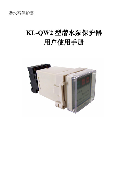
潜水泵保护器KL-QW2型潜水泵保护器用户使用手册目录1.概述 (2)1.1.性能特点 (2)1.2.原理 (2)1.3.主要性能 (2)2.售后服务 (3)3.保护控制器的使用 (3)3.1.外形尺寸图与安装(高X宽X长)48X48X110(MM) (3)3.2.产品使用与接线说明 (4)4.其它 (6)5.附录 (6)1.概述1.1.性能特点KL-QW系列潜水泵保护器(以下简称保护器),适用于“潜水泵保护器”,“潜水推进器”的保护与控制。
可适用于南京贝特、上海川源、蓝深集团、扬子江泵业、南京布鲁克林或其它类同类的所有潜水泵保护器。
1.2.原理根据QW2型保护器长年工作在水下的结构与特性在对QW2型保护器的保护装置中必要加入油室泄漏保护与电机超温保护:油室泄漏保护:在潜水泵保护器油室内置入水份检测电极,在油室中如果出现有水份超限时电极出现信号跳变,QW2潜水泵保护器能检测到此信号的变化,而停止QW2潜水泵保护器运行并以故障指示。
电机超温保护:在潜水泵保护器三相电机绕组每相上安装135℃的PTC热敏电阻,在任一相绕组出现温度上升到135℃±5时,电阻值出现跳变,QW2潜水泵保护器能检测到此信号的变化,而停止QW2潜水泵保护器运行并以故障指示。
电机过载保护:在潜水泵保护器三相电机运行回路上每相线上串入相对应用电流的热继电器,一旦电流过大,热继电器会状态跳变,QW2潜水泵保护器能检测到此信号的变化,而停止QW2潜水泵保护器运行并以故障指示。
低水位保护:在潜水泵保护器工作的水池中,使用液位检测器检测水位,但水位低于潜水泵保护器工作的水位时,液位检测器会状态跳变,QW2潜水泵保护器能检测到此信号的变化,而停止QW2潜水泵保护器运行并以低水位指示。
1.3.主要性能传感器供电:传感器DC12V供电。
供电电源变压器隔离。
信号输入:超温信号:电机超温保护。
泄漏信号:油室泄漏保护。
输入回差控制:±2%。
潜水泵使用规范
内蒙古××煤化科技有限公司潜水排污泵使用规范编写:审核:审定批准:日期:潜水排污泵使用规范1、长期停用的潜水电泵再次使用前,应拆开最上一级泵壳,盘动叶轮后再行启动,防止部件锈死启动不出水而烧坏电动机绕组。
这对充水式潜水电泵更为重要。
2、潜污泵在无水的情况下试运转时,运转时间严禁超过额定时间。
吸水池的容积能保证潜污泵开启时和运行中水位较高,以确保电机的冷却效果和避免因水位波动太大造成的频繁启动和停机,大中型潜污泵的频繁启动对泵的性能影响很大。
3、安装漏电保护器漏电保护器也叫保命器,它的作用从“保命器”这三个字就可以理解。
因为潜水泵在水下工作,容易漏电造成电能损失甚至引发触电事故。
如果装有漏电保护器,只要潜水泵漏电值超过漏电保护器的动作电流值(不超过30毫安),漏电保护器就会切断潜水泵的电源,避免漏电浪费电能,确保安全。
4、电源电压异常莫开机,当相电压低于198伏,线电压低于342伏时,潜水泵电机转速下降,当达不到额定转速的70%时,启动离心开关会闭合,造成启动绕组长时间通电而发热甚至烧坏绕组和电容器。
相反,电压过高引起电机过热而烧坏绕组。
因此,潜水泵在作业中,操作者必须随时观察电源电压值,若低于额定电压10%以下,高于额定电压10%以上,应使电机停止运转,找出原因并排除故障。
5、莫让潜水电泵长期超负荷工作为避免潜水电泵长期超负荷工作,不要抽含沙量大的水并随时观察电流值是否在铭牌上规定的数值,若发现电流过大,应停机检查。
另外,电泵脱水运行的时间不宜过长,以免使电机过热而烧毁。
6、避免频繁开关,不要频繁地开关潜水泵,这是因为电泵停转时管路内的水产生回流,若立即开机,会使电机负载启动,导致启动电流过大而烧坏绕组。
另外,潜水泵过于频繁开、停将损坏承受冲击能力较差的零部件,并带来整个电泵的损坏。
由于启动时电流很大,频繁启动也会烧坏潜水泵电动机绕组。
7、电机的旋转方向要正确应搞清电机的旋转方向,现在有许多类型的潜水泵正转和反转时皆可出水,但反转时出水量小、电流大,其反转时间长了会损坏电机绕组。
人民电器 RDM1L系列漏电断路器(透明壳) 使用说明书

R D M1L剩余电流动作断路器符合标准:GB/T 14048.2警告1 漏电断路器对同时接触被保护电路两线引起的触电危险不能进行保护,使用时请务必注意。
2 漏电断路器进行动作特性试验时,应使用经国家有关部门检测合格的专用测试台,严禁利用相线直接触碰接地装置的试验方法。
3 漏电断路器主要功能是对有致命危险的人身触电提供间接接触保护,额定剩余动作电流不超过0.03A的漏电断路器在其他保护措施失效时,也可以作为直接接触电击事故基本防护措施的补充保护措施(不包括对相与相、相与N线间形成的直接接触电击事故的保护),但不能作为唯一的直接接触保护。
4 严禁湿手操作漏电断路器,否则可能发生电击事故。
注意1 漏电断路器安装场所应无爆炸危险、无腐蚀性气体,并应注意防潮、防尘、防震动。
2 漏电断路器安装位置应避开强电流电线和电磁器件,避免磁场干扰。
3 四极漏电断路器上接线端子必须接入中性线,以利于电子线路正常工作。
安装时必须严格区分中性线(N)和保护线(PE),经过漏电断路器的中性线不得作为保护线, 不得重复接地或接设备外露可导电部分。
保护线不得接入漏电断路器。
4 漏电断路器的漏电、过载、短路保护特性均由制造厂整定,在使用中不可随意调整,以免影响性能。
5 绝缘测试本漏电断路器出厂前已按标准规定进行绝缘测试,因漏电断路器带有电子线路板,安装前如进行复测,必须按如下步骤:a) 用500V DC兆欧表;b) 在漏电断路器处于断开状态时, 对进出联结板1-2、3-4、5-6之间分别进行;断路器处于闭合状态时,严禁对漏电断路器的1-5或2-6之间进行测试;c) 绝缘电阻应不小于10MΩ。
1 用途及适用范围RDM1L系列剩余电流动作断路器(以下简称断路器),主要适用于交流50Hz,额定工作电压为400V,额定电流至800A的配电网络中,用来对人提供间接接触保护,也可用来防止因设备绝缘损坏, 产生接地故障电流而引起的火灾危险,并可用来分配电能和保护线路及电源设备的过载和短路, 还可作为线路的不频繁转换和电动机不频繁启动之用。
- 1、下载文档前请自行甄别文档内容的完整性,平台不提供额外的编辑、内容补充、找答案等附加服务。
- 2、"仅部分预览"的文档,不可在线预览部分如存在完整性等问题,可反馈申请退款(可完整预览的文档不适用该条件!)。
- 3、如文档侵犯您的权益,请联系客服反馈,我们会尽快为您处理(人工客服工作时间:9:00-18:30)。
电子潜水泵漏电断路器使用说明
1.首先使用螺丝刀将产品接通电源。
2.其次按下产品上面的试验按钮,观察保护器是否跳针,若跳闸,说明产品是完好的,若没有跳闸,说明产品是坏的,是无法起到缺相保护的作用的。
3.然后将保护器上面的闸刀重新开启,即将闸刀向上拉即可。
4.最后将产品的输出端接三相用电设备即可,然后就能够正常使用!
漏电断路器也叫保命器,它的作用从“保命器”这三个字就可以了解。
因为潜水泵在水下作业,容易漏电形成电能损失甚至引发触电事端。
假如装有漏电保护器,只要潜水泵漏电值超过漏电保护器的动作电流值(一般不超过30毫安),漏电保护器就会堵截潜水泵的电源,防止漏电糟蹋电能,确保安全。
潜水泵注意事项:不要频繁地起停潜水泵,这是因为电泵停转时会发生回流,若立即开机,会使电机负载发动,导致发动电流过大而烧坏绕组。
因为发动时电流很大,频繁发动也会烧坏潜水泵电动机绕组。