光照度变送器说明书
仁科光照温湿度变送器(WIFI型)使用说明书
光照温湿度变送器使用说明书(WIFI型)文档版本:V1.0目录1.产品介绍 (4)1.1产品概述 (4)1.2功能特点 (4)1.3主要技术指标 (4)1.4产品选型 (5)1.5设备信息 (5)1.6产品拓扑图 (6)2.设备安装及使用 (7)2.1设备安装说明 (7)2.2设备使用 (8)3.监控平台介绍 (11)4.常见问题及解决办法 (12)5.注意事项 (12)6.联系方式 (13)7.文档历史 (13)8.附录 (14)1.1产品概述RS-GZ-WIFI-2是一款WIFI无线数据传输的工业级通用光照度变送器,该变送器采用高精度感光元件,反应迅速灵敏。
采集数据并通过WIFI方式上传到服务器。
本产品充分利用已架设好的WIFI通讯网络实现数据采集和传输,达到数据集中监控的目的。
可大大减少施工量,提高施工效率和维护成本。
设备10-30V宽压供电,外壳防护等级高,能适应现场各种恶劣条件。
1.2功能特点RS-公司代号GZ/GZWS-光照度变送器WIFI-WIFI型2壁挂王字壳1.5设备信息尺寸产品外观及示意序号名称内容①设备贴膜上面带有产品logo以及名称②NFC感应区域使用NFC配置软件配置时,手机NFC触碰此区域【注意】读取及下发参数时,需等待APP提示成功/失败后,再拿开手机③安装孔位使用配件膨胀螺丝包,将设备安装至墙面等需要安装的位置④精装护套⑤电源线DC5.5*2.1规格;使用配件电源适配器插入供电包装内容主设备×1产品合格证、保修卡×1膨胀螺丝包(含2个自攻螺丝及2个膨胀塞)×112V电源适配器×1USB转485(选配)×11.6产品拓扑图云平台完全免费2.设备安装及使用2.1设备安装说明设备主体的安装2.2设备使用接通电源将电源适配器连接至设备的供电接口,再接通电源连接至网络1下载配置工具,使用QQ扫描二维码(仅限安卓手机),点击“客户端本地下载”,下载完成后根据手机提示将APP安装。
迅捷Fluke IRR1-SOL光照度仪用户手册说明书
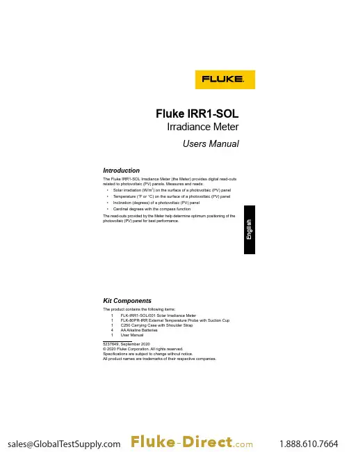
Fluke IRR1-SOL Irradiance MeterUsers Manual5237649, September 2020© 2020 Fluke Corporation. All rights reserved.Specifications are subject to change without notice.All product names are trademarks of their respective companies.IntroductionThe Fluke IRR1-SOL Irradiance Meter (the Meter) provides digital read-outs related to photovoltaic (PV) panels. Measures and reads:• Solar irradiation (W/m 2) on the surface of a photovoltaic (PV) panel • Temperature (°F or °C) on the surface of a photovoltaic (PV) panel • Inclination (degrees) of a photovoltaic (PV) panel• Cardinal degrees with the compass functionThe read-outs provided by the Meter help determine optimum positioning of the photovoltaic (PV) panel for best performance. Kit ComponentsThe product contains the following items:1 FLK-IRR1-SOL/001 Solar Irradiance Meter1 FLK-80PR-IRR External Temperature Probe with Suction Cup 1 C250 Carrying Case with Shoulder Strap4 AA Alkaline Batteries1 User ManualSymbolsSafety InformationA Warning identifies hazardous conditions and procedures that are dangerous to the user. A Caution identifies conditions and procedures that can cause damage to the Product or the equipment under test.� WarningTo prevent personal injury and damage to the Product:• Read the entire users manual before using the Meter.• Use the Meter only as described in the Users Manual otherwisethe protection provided by the equipment may be impaired.• Inspect the Meter before use. Do not use it if it appears damaged. • Do not use the Meter around explosive gas, vapor, and/or in damp or wet environments that exceeds IP40.• The Meter contains no user-serviceable parts. Do not openthe instrument.• Use only AA batteries, properly installed in the Meter case, topower the Meter (see Battery Replacement).• To avoid false readings, replace the batteries as soon as the low battery indicator appears.• Remove the batteries if the Meter is not used for an extendedperiod of time, or if stored in temperatures above 140 °F (60 °C).If the batteries are not removed, battery leakage can damage the Meter.• Have the Meter serviced only by qualified service personnel.12OperationChange Temperature UnitsConnect the External Temperature ProbeHold Function346Measuring Inclination and Cardinal Direction Place the Meter directly onto the PV panel to get accurate tilt.The compass measurement will require a two-step process for accurate cardinal direction.Step 1: Perform irradiance, temperature and inclination measurements with meter placed on and aligned with the PV panel. The compass function will show “---” when the tilt angle is above 20 degrees. At a tilt angle of <20 degrees any compass reading shown will be inaccurate due to the influence by surrounding metal objects.Step 2: Perform the compass measurement away from the PV panel by holding the meter or placing meter on a horizontal surface (0 to 20 degrees tilt) pointing the tip of the meter in the direction that the PV panel faces. Keep away from any metal objects.NoteThe compass will reference magnetic north. The compass reading will be unreliable if the meter is placed on or near objects containing metal(including solar panels, metal roofs, concrete surfaces with rebar, etc).7MaintenanceBattery Replacement The battery compartment on the back of the Meter makes it easy to change the batteries. Use four (4) AA 1.5 V alkaline batteries.Note: Batteries are not pre-installed in the meter.1. Make sure that the meter is turned off.2. Use a screw driver to unscrew the captive screw.3. Remove the battery cover.4. Install batteries.5.Replace the battery cover and secure it with the provided screw.Cleaning Periodically wipe the case with a damp cloth and mild detergent.� CautionTo prevent damage to the Meter:• The Meter contains no user-serviceable parts. To avoid injury, or damage to the Meter, do not open the case. • To avoid damaging the Meter, do not use abrasives or solvents to clean the Meter case.Storage During longer periods of non-use (>60 days), remove and store the battery separately.Service and Parts Only a qualified technician should service the Meter. For service information, contact your nearest Fluke dealer or service center.SpecificationsIrradianceMeasuring range ................0 to 1400 W/m²Resolution ..........................1 W/m²Measuring Accuracy ...........±(5 % + 5 Digit)Temperature MeasurementMeasuring range (°C) ......... -30 °C to 100 °C (-22 °F to 212 °F)Resolution .......................... 0.1 °C (0.2 °F / 1 °F @ > 100 °F)Measuring Accuracy ........... ±1 °C (±2 °F) @ -10 °C to 75 °C (14 °F to 167 °F),±2 °C (±4 °F) @ -30 °C to -10 °C (-22 °F to14 °F) and 75 °C to 100 °C (167 °F to 212 °F) Note: Temperature measurement response time: ~30 sec.Inclination AngleMeasuring range ................-90° to +90°Resolution ..........................0.1°Measuring Accuracy ...........±1.5° @ -50° to +50°,±2.5° @ -85° to -50° and +50° to +85°,±3.5° @ -90° to -85° and +85° to +90° CompassMeasuring range ................0° to 360°Resolution ..........................1°Measuring Accuracy (7)Note:a) M easurements valid for device inclination between -20° and +20° tohorizontal. Outside that range on LCD will be shown "---".b) Result is referred to magnetic north.Operating TemperatureOperating temperatures .....I RR1-SOL: -20 °C to 50 °C, humidity <80%,noncondensing80PR-IRR: -30 °C to 100 °CStorage temperature ..........-30 °C to 60 °C (humidity <80%)Altitude ...............................0 m to max. 2000 mElectromagnetic Compatibility (EMC)InternationalIEC 61326-1: Portable Electromagnetic EnvironmentCISPR 11: Group 1, Class AGroup 1: Equipment has intentionally generated and/or uses conductively-coupled radio frequency energy that is necessary for the internal function of the equipment itself.Class A: Equipment is suitable for use in all establishments other than domestic and those directly connected to a low voltage power supply network that supplies buildings used for domestic purposes. There may be potential difficulties in ensuring electromagnetic compatibility in other environments due to conducted and radiated disturbances.Caution: This equipment is not intended for use in residentialenvironments and may not provide adequate protection to radio reception in such environments.Korea (KCC)Class A Equipment (Industrial Broadcasting & Communication Equipment) Class A: Equipment meets requirements for industrial electromagnetic wave equipment and the seller or user should take notice of it. Thisequipment is intended for use in business environments and not to be used in homes.USA (FCC)47 CFR 15 subpart B. This product is considered an exempt device perclause 15.103.ProtectionIP Protection .......................IP40Power Supply & Battery LifeBatteries .............................4 AA Alkaline BatteriesBattery Life (typical) ...........50 hours (>9000 readings)Auto Power Off ..................30 minutesDimensionsL x W x H ............................ 150 x 80 x 35 mm(5.90 x 3.14 x 1.37 in)Weight ................................231g (0.5lb)8。
光照度传感器MODBUS
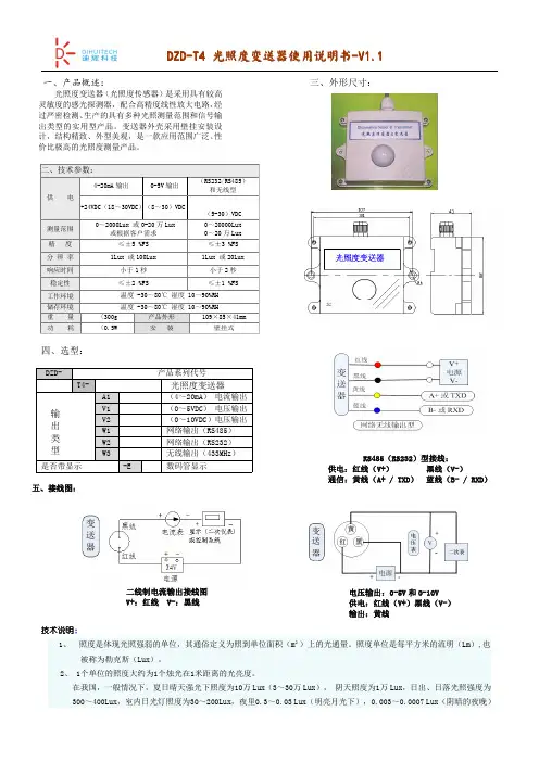
四、选型:技术说明:1、照度是体现光照强弱的单位,其通俗定义为照到单位面积(m²)上的光通量。
照度单位是每平方米的流明(Lm),也被称为勒克斯(Lux)。
2、1个单位的照度大约为1个烛光在1米距离的光亮度。
在我国,一般情况下,夏日晴天强光下照度为10万Lux(3~30万Lux),阴天照度为1万Lux,日出、日落光照强度为300~400Lux,室内日光灯照度为30~200Lux,夜里0.3~0.03Lux(明亮月光下),0.003~0.0007Lux(阴暗的夜晚)一、产品概述:光照度变送器(光照度传感器)是采用具有较高灵敏度的感光探测器,配合高精度线性放大电路,经过严密检测、生产的具有多种光照测量范围和信号输出类型的实用型产品。
变送器外壳采用壁挂安装设计,结构精致、外型美观,是一款应用范围广泛、性价比极高的光照度测量产品。
五、接线图:三、外形尺寸:RS485(RS232)型接线:供电:红线(V+)黑线(V-)通信:黄线(A+/TXD)蓝线(B-/RXD)电压输出:0-5V 和0-10V 供电:红线(V+)黑线(V-)输出:黄线二线制电流输出接线图V+:红线V-:黑线六、通信说明:(只针对于RS232RS485和无线输出型)典型推荐:室内测量量程0~20000Lux ,室外或温室测量量程:0~20万Lux本产品采用标准Modbus-RTU 通讯协议,产品出厂默认地址为1,波特率为9600,8位数据位,无奇偶校验,1位停止位0~20000Lux光照度上传的数据为真实值0~20万Lux 光照度上传的数据需乘以10才为真实值(采集得到的数据为0~20000)6.1查询地址为1的仪表的光照度值(读输入寄存器)6.2查询地址为1的仪表读保存寄存器6.3写入单个保存寄存器,读从机输入寄存器(4X 类型)中的二进制数据,寄存器所对应的地址分别为0-136.4写入把地址波特率修改为4800(4800的16进制为12C0)七、注意事项:1、使用前请认真阅读说明书、确保接线正确:任何错误接线均有可能对变送器造成不可逆伤害。
光照计使用方法
光照计使用方法
光照计是一种测量光照强度的仪器,常用于光照设计、室内外光照状况分析以及植物生长等应用。
以下是光照计的使用方法:
1. 打开光照计的电源开关。
2. 设置光照计的单位,通常有勒克斯(lux)和法律特(foot-candle)两种选择。
根据需要选择合适的单位。
3. 将光照计的光敏元件(一般是光敏电阻或光敏二极管)暴露在希望测量光照强度的位置,并保持稳定。
4. 读取光照计上的显示数值,即为当前测得的光照强度。
可以在不同位置进行多次测量,以获取更准确的平均值。
5. 如果需要记录测量结果,可以将测量数据记录下来以便后续
分析使用。
6. 使用完毕后,关闭光照计的电源开关,以节省能源并延长电池寿命。
值得注意的是,不同的光照计在使用方法上可能会略有不同,因此在使用前最好查看光照计的说明书,以确保正确操作。
另外,在不同环境下,光照计的测量结果可能会受到其他因素(如摄入角度、反射等)的影响,因此在使用时应尽量保持稳定的测量条件,以获取准确的测量结果。
光照度变送器
光照度变送器用户手册(485型)文档版本:V1.2光照度变送器用户手册 (1)一产品介绍 (2)二设备安装说明 (3)三配置软件安装及使用 (4)四通信协议 (5)五常见问题及解决办法 (7)六联系方式 (7)七文档历史 (7)八附录:壳体尺寸 (7)一产品介绍1、产品概述该变送器广泛适用于适用于室内外环境监测,农业大棚,花卉培养等需要光照度监测的场合。
该传感器采用全隔离,传感器内输入电源,感应线,信号输出三部分完全隔离。
安全可靠,外观美观,安装方便。
2、功能特点本产品采用高灵敏度的感光探头,信号稳定,精度高。
具有测量范围宽、线形度好、防水性能好、使用方便、便于安装、传输距离远等特点。
3、主要技术指标供电电源:9-24V DC光照度测量范围:0-65535lux 光照精度:±5%FS(25℃)存储环境:-40℃~80℃4、系统框架图系统方案框图二设备安装说明2.1设备安装前检查设备清单:●水浸报警器设备1台●12V/2A 防水电源1台(选配)UPS 电源(选配)9~24V DC1号设备2号设备3号设备n 号设备485总线USB 转485或232转485监控电脑市电220VUSB转485(选配)2.2接线宽电压电源输入9~24V均可。
485信号线接线时注意A\B两条线不能接反,总线上多台设备间地址不能冲突。
线色说明电源棕色电源正(9~24V DC)黑色电源负通信黄色485的A端蓝色485的B端三配置软件安装及使用3.1软件安装使用前分别双击,按照提示进行注册,注册完成后,双击,进入设置界面(注:win7电脑请右击此设置工具,以管理员身份注册并运行)。
3.2参数设置1、选择正确的COM口(可在“我的电脑—设备管理器—端口(com和lpt)”里面查看COM端口。
)2、单独接上一台设备并上电,单击软件的测试波特率,软件会测试出当前设备的波特率以及地址,默认波特率为4800bit/s,默认地址为0x01。
光照度测试仪使用方法
光照度测试仪使用方法光照度测试仪是一种测量光源发出光照强度的仪器,是光电工程、光学测量、环境监测等领域中常用的工具之一。
以下是光照度测试仪的使用方法和注意事项的详细描述。
1. 准备工作在使用光照度测试仪之前,需要确保仪器正常工作,并按照说明书中的指示进行操作。
首先,将仪器与光源进行比较,以确保仪器的准确性。
然后,将测试样品放置在仪器上进行测试。
在测试之前,需要将测试样品清洗干净,并确保测试样品表面平整,没有任何凸起或皱折。
2. 测量光源的光照强度将测试样品放置在仪器上进行测试时,需要将仪器的测量范围设置为被测试样品的位置。
然后,将光源放置在测试样品的表面上,并使用仪器上的光源按钮进行测量。
根据仪器上显示的测量结果,可以计算出光源的光照强度。
3. 调整测试样品的位置在测试过程中,可能需要调整测试样品的位置,以确保测试结果的准确性。
例如,如果测试样品表面存在凸起或皱折,需要将其抚平,以确保测试结果的准确性。
4. 记录测试结果在测试过程中,需要记录测试样品的位置和测试时间,并根据仪器上显示的测量结果计算出光源的光照强度。
根据测试结果,可以了解被测试样品的光照强度分布情况、光源的光照强度分布情况等。
5. 分析测试结果在测试完成后,需要对测试结果进行分析,并根据分析结果做出相应的决策。
例如,如果测试结果中发现被测试样品表面存在光照强度不均匀的情况,需要考虑使用光源的均匀性来改善测试结果。
光照度测试仪是一种非常重要的测试工具,可以用于测量光源的光照强度。
在使用光照度测试仪时,需要认真操作,并按照说明书中的指示进行测试和分析。
通过正确使用光照度测试仪,可以更好地了解被测试样品的性能,做出更准确的决策。
光线照度计操作说明书
德信诚培训网
更多免费资料下载请进: 好好学习社区 TES-1334A 光线照度计操作说明书
在您使用本产品前,请详细阅读本说明书,它将教您正确的操作方法及简易的检查处理要领,以便能发挥本表坚固耐用之优良性能。
数字式照度计是一台精密仪器,适合在各种场合测量其照度。
一、数字照度计的特点:
◆TES -1330A -测量范围由 0.01lux~20,000lux (勒克斯)。
◆TES -1332A -测量范围由 0.1lux~200,000lux (勒克斯)。
◆TES -1334A -测量范围由 0.01lux/fc~20,000lux/fc (勒克斯 /呎烛光)。
◆准确度高以及反映速度快。
◆TES -1334峰值锁定功能,能追踪大于50.0ms 的脉冲信号,锁定其峰值。
◆读值锁定功能,可锁定测定值。
◆符号及单位显示,读取方便。
◆自动归零。
二、数字照度计的规格:
◆显 示:31/2位液晶显示器显示,最大读值1999。
◆测量范围:
◇TES -1330-20,200,2,000,20,000lux(20,000lux 文件显示之读值需×10才为正确照度值) ◇TES -1332-200,2,000,20,000,200,000lux(20,000lux 文件显示之读值需×10,及200,000lux 文件显示之读值需×100才为正确照度值)
◇TES -1334-20,200,2,000,20,000lux/fc(20,000lux/fc 文件显示之读值需×100才为正确照度值)
◇注:1fc =10.76Lux。
光照度测量仪 LumiTop 2700 4000 产品说明书
LumiTop 2700/4000 Spectrally enhanced imaging colorimeter\\ L ab specs meet production speedThe LumiTop 2700/4000 combines the accuracy of Instrument Systems’ well-known spectroradiometers of the CAS series with the obvious advantages of imaging colorimetry. Principle: Fast and accurate With the help of a polarization insensitive, three-way beam splitter, the LumiTop 2700/4000 mergesan RGB CCD/CMOS camera anda flicker diode with the high-end spectroradiometer of the CAS series. This innovative design allows for simultaneous measurements of all components, which may result in significant time-savings.At the same time, the extremely accurate spectral information of the spectroradiometer measurement is used as reference for the camera measurement. This guarantees spectroradiometric accuracy across the whole 2D image.As a result, the LumiTop 2700/4000 not only performs fast 2D measurements with unprecedented accuracy but also offers all the advantages of classical imaging colorimetry. Perfect for productionBecause of this combination, theLumiTop 2700/4000 is perfectfor use in display productionlines or quality control, where thebenefits and capabilities of both,the accurate spot measurement ofspectroradiometers and the lateralresolution of camera measurementsare highly valued.All-in-one solutionMany different test applications cannow be organized in a single teststation:y M easurement of luminance andcolory E valuation of color and luminanceuniformity or Mura effectsy P ixel metrology including pixeldefect analysisy C ontrast measurementy A nalysis of white balance or colorgamuty F licker and luminance modulationmeasurementy A nalysis of the acquired spectraEasy to integrate intoproduction linesThe LumiTop 2700/4000 isintegrated in Instrument Systems’comprehensive new software“LumiSuite”, which comes witha user-friendly GUI for laboratoryapplications and a powerfulsoftware development kit for easyimplementation into any productionline. The spectra measured asreference for the camera can beanalyzed in more detail usingInstrument Systems’ well-knownsoftware SpecWin Pro.Independent of displaytechnologyDue to the high absolute accuracyof the CAS spectroradiometer thatis used as reference during eachmeasurement, the performanceof the solution is excellent for anydisplay technology (or any otherhomogeneous samples). Moreoverno golden sample or user calibrationsare needed. This makes the solutionparticularly favorable when OLEDs orother narrow-banded light sourceshave to be investigated where classicalimaging colorimeters based on XYZfilter technologies reach their limits.ModularityThe LumiTop 2700/4000 is designedas a modular accessory to any of thespectroradiometers of the CAS series.Thus the same spectroradiometerscan also be used with the telescopicoptics TOP 150 or TOP 200.\\Technical specifications1)Inclusive lens and fiber exit.2)Without CAS, with mode mixer.3)E xternal neutral density filters on the lens (OD 0.3/0.6/0.9) are available for increasingthe upper measurement limit or measuring modulated light sources.4)L ower measurement limit based on a signal to noise ratio of 10:1 for maximumexposure time (60 seconds LumiTop 2700 / 10 seconds LumiTop 4000). Uppermeasurement limit based on a signal level < 80 % for a white (non-modulated) LED light source using for minimum exposure time (1 ms LumiTop 2700 / 27 µs LumiTop 4000).5)T ypical value for maximum deviation over the FOV relative to the CAS spot;calculated for an image with 16 pixels (LumiTop 2700) / 21 pixels (LumiTop 4000) cropped at each edge and 10 by 10 pixels (LumiTop 2700) / 13 by 13 pixels(LumiTop 4000) binning (34 averages) immediately after calibration with reference used for flat-field correction.6)2σ of repeated measurements of one instrument (L ≈ 100 cd/m2, autoexposure).7)R NU (response non-uniformity) is defined as 99.7 % percentile of the deviationof the mean image value; calculated for an image with 16 pixels (LumiTop 2700) /21 pixels (LumiTop 4000) cropped at each edge and 10 by 10 pixels (LumiTop 2700) /13 by 13 pixels (LumiTop 4000) binning (34 averages) immediately after calibrationwith reference used for flat-field correction.8)T ime between beginning of two subsequent measurements using the SDK;determined with a camera exposure time of 20 ms and CAS exposure time of200 ms for a white LED (L ≈ 500 cd/m2). Depends mainly on PC processing capability.9)L ower measurement limit based on a signal to noise ratio of 10:1 for maximumexposure times 65 s for CAS 140D and CAS 140CT, 20 s for CAS 120. Uppermeasurement limit based on a signal level < 80 % for a white (non-modulated) LED light source using a CAS internal optical density filter OD4 and minimum exposure time (10 ms CAS 140CT / 4 ms CAS 140D and CAS 120). Values valid for CAS 140CT, CAS 120 with 100 μm and CAS 140D with 250 μm slit width.10)I mmediately after calibration relative to calibration standard.11)I mmediately after calibration.12)M aximum deviation from average of repeated CAS measurements with a linearpolarized light source and varying polarization angle.13)L ≈ 150 cd/m2, 30 Hz, 10 % sine wave.14) 2σ of repeated measurements of one instrument.15)Distance between DUT and front plate of LumiTop.We bring quality to light.Instrument Systems GmbH Kastenbauerstr. 281677 Munich, Germany ph: +49 (0)89 45 49 43-58 fax: +49 (0)89 45 49 43-11 **************************b _L u m i T o p _e n _V 1.7Instrument Systems is continually working on the further development of its products. Technical changes, errors and misprints do not justify claims for damages. For all other purposes, our Terms and Conditions of Business shall be applicable.。
光照度传感器 LH-LR2000 说明书
光照度传感器说明书适用型号:LH-LR2000修订记录:目录1.产品介绍 (2)2.规格参数 (2)3.产品尺寸 (3)4.485通信协议与数据格式 (3)4.1.通讯基本参数 (3)4.2.数据帧格式定义 (3)4.3.寄存器地址 (4)4.4.参数读取 (5)5.模拟量协议 (6)6.电气接线 (6)7.售后服务 (7)7.1.售后服务承诺 (7)7.2.免责声明 (8)7.3.联系方式 (8)1.产品介绍该变送器广泛适用于农业大棚、花卉培养等需要光照度监测的场合。
传感器内部的输入电源、感应探头、信号输出三部分完全隔离。
安全可靠,外观美观,安装方便。
2.规格参数3.产品尺寸图3.14.485通信协议与数据格式4.1.通讯基本参数4.2.数据帧格式定义采用Modbus-RTU 通询规约,格式如下:地址码=1字节功能码=1字节数据区=N字节错误校验=16位CRC码结束结构>=4字节的时间地址码:为设备的地址,在通询网络中是唯一的。
功能码:主机所发指令功能提示。
数据区:数据区是具体通询数区,注意16bits数据高字节在前。
CRC码:二字节的校验码。
地址码功能码寄存器起始地址寄存器长度校验码低位校验码高位问询1字节1字节2字节2字节1字节1字节地址码功能码有效字节数数据区校验码低位校验码高位应答1字节1字节1字节2字节1字节1字节4.3.寄存器地址4.4.参数读取(1)例:读取设备地址为01的传感器光照度地址码功能码起始地址数据值校验码低位校验码高位问询0x010x030x00,0x070x00,0x020x750xCA地址码功能码字节数数据值校验码低位校验码高位应答0x010x030x040x000x00,0x060xF60x7A0x31注释:光照度计算说明:000006F6H(十六进制)=1782=>光照度=1782Lux(2)例:查询设备地址、波特率地址码功能码起始地址数据值CRC低位CRC高位问询0x010x030x01,0x000x00,0x020xC50xF7应答地址码功能码有效字节数设备地址波特率CRC 低位CRC 高位0x010x030x040x00,0x010x00,0x030xEB0xF2读出设备地址为1;波特率为9600。
光照度变送器产品使用手册说明书
1光照度变送器产品使用手册1概述LT-CG-S/D-001-A0220-12光照度传感器探头选用国外进口感光芯片,菲尼尔透镜聚光,标准0~65535LUX 测量量程,完全满足室内光照度测量。
产品测量精度高,线性度好。
作为现场采集从站,按照标准MODBUS-RTU 通信协议RS485数字信号输出,适合远距离组网传输。
可选配液晶屏现场显示测量数据,还可选配1路继电器报警输出。
完全兼容组态王等多种上位机组态软件,易与第三方设备配套。
可广泛用于农业大棚、智能养殖、智能家居及工厂商厦等环境监测领域。
2外形规格3产品技术指标规格型号:LT-CG-S/T-005-A0121-12-V1.1(包含液晶屏)LT-CG-S/T-005-A0120-12-V1.1(不含液晶屏)LT-CG-S/T-005-A0121-DO-12-V1.1(包含液晶屏、1路报警)可见光检测波段:可见光,波长400~730nm,波峰560nm光照度测量范围:0~70KLUX光照度测量精度:±7%光照度分辨率:1LUX光照度测量重复性:±5%测量稳定时间:0.5秒响应时间:<1秒2工作环境:-20~55度,5~95%RH存储环境:-25~60度供电电压:DC7~24V显示方式:LCD液晶屏(选项)液晶屏规格:08022行显示,每行8个字符变送器可选配1路报警输出,继电器控制报警设备动作通信接口:RS485通信速率:2400、4800、9600、19200、38400、115200。
默认9600bps.通信协议:MODBUS-RTU数据格式:1、8、1、9600(1位起始位、8位数据位、1位停止位、无校验、9600bps波特率)通信方式:作为MODBUS从站,采用主从轮询方式相应主站请求,将数据上传。
终端类别:从站节点地址:001~255,由拨码开关硬件设定节点数量:31传输距离:500米(RS485通信专用电缆)变送器出厂前经过三防处理,确保高温高湿特殊环境下长期使用。
- 1、下载文档前请自行甄别文档内容的完整性,平台不提供额外的编辑、内容补充、找答案等附加服务。
- 2、"仅部分预览"的文档,不可在线预览部分如存在完整性等问题,可反馈申请退款(可完整预览的文档不适用该条件!)。
- 3、如文档侵犯您的权益,请联系客服反馈,我们会尽快为您处理(人工客服工作时间:9:00-18:30)。
光照度变送器说明
一光照度传感器:
光照度传感器、照度变送器是采用具有较高灵敏度的感光探测器,配合高精度线性放大电路,经过严密检测、生产的具有多种光照测量范围和信号输出类型的实用型产品。
变送器外壳采用壁挂安装设计,结构精致、外型美观,是一款应用范围广泛、性价比极高的光照度测量产品。
二技术参数
技术指标
量程0~2000/20000Lux
精度±5%FS(25℃)
温度漂移0.2%FS/℃
重复性<1%FS
响应时间≤60S达到变化的90%输出信号4-20mA/0~5V
RS485(Modus协议)供电电源DC12-24V
工作环境温度:0℃~50℃
湿度:≤94%RH 显示LED显示(可选)
输出负载电压输出型:>3KЛ
电流输出型:≤500R
安装方式壁挂式
三接线图
+Vs GND485_A485_B Vout Iout COM NO 电源
PC
四通信协议说明
我们的照度变送器采用MODBUS规约,原因是该规约文本容易得到,协议本身也非常的简单。
而且该规约是一个开放的,有着许多国内厂商和国际厂商的支持。
MODBUS规约是MODICOM公司开发的,版权归其所有。
根据我们设备的情况,我们仅仅实现了MODBUS的一个小型子集,没有完全实现其所有内容,已经能够满足我们所有的需要。
我们的接口采用RS485接口,比RS232具有更高的通信速率和更远的通信距离。
每个字节包括1个起始位,8个数据位,无校验位,1位停止位。
本机采用部分的MODBUS协议,使用了03和06两个命令。
可读取内部的5个寄存器变量,可写入(设置)3个寄存器变量。
4.1读取命令帧格式为(假设本机地址为1,数据均为16进制):
01030000000585C9
解释:
01:从机地址
03:读寄存器命令
0000:第一个寄存器地址
0005:读取寄存器个数
85C9:CRC校验码
采用MODBUS调试助手界面的设置如下:
如下图所示,各个寄存器内容代表含义为:
0:从机地址
1:波特率
数值与波特率的对应关系如下:
1:1200
2:2400
3:4800
4:9600(默认)
5:14400
6:19200
7:38400
8:56000
9:57600
2:报警阀值(超过报警阀值继电器就会打开)
3:报警状态(0:表示照度值没有超过报警阀值1:表示照度值超过报警阀值)4:光照度Lux值(十进制数值)
读取5个寄存器的命令(返回的数据是十六进制)
发送:01030000000585C9
返回:01030A000100042710000000922A5F
返回命令解释:
01从设备地址
03读功能号
0A返回的数据个数
0001从设备地址(第一个寄存器)
0004波特率(第二个寄存器)注:04对应波特率为9600
2710报警阀值(第三个寄存器)
0000报警状态(第四个寄存器)
0:表示照度值没有超过报警阀值1:表示照度值超过报警阀值
0092照度值(Lux)注:十六进制
2A CRC校验低8位
5F CRC校验高8位
只读取照度值的命令:
发送:010*********C5CB
返回:0103020056387A
返回命令解释:
01从设备地址
03读功能号
02返回的数据个数
0056光照度值(Lux)十六进制数值
38CRC校验低8位
7A CRC校验高8位
4.2写入命令帧格式为(假设本机地址为1,需写入的数据为10000十六进制为0X2710)
0106000227103236
解释:
01:从机地址
06:写入寄存器命令
0002:寄存器地址
2710:写入的数据为10000
32:CRC校验低8位
36:CRC校验高8位
修改报警值为10000的命令
发送:0106000227103236
返回:0106000227103236
发送命令解释:
解释:
01:从机地址
06:写入寄存器命令
0002:寄存器地址
2710:将报警阀值修改为0X2710(十进制为10000)
32:CRC校验低8位
36:CRC校验高8位
返回命令解释:
01:从机地址
06:写入寄存器命令
0002:寄存器地址
2710:修改成功后的报警阀值0X2710(十进制为10000)32:CRC校验低8位
36:CRC校验高8位
修改地址的命令:(假设本机地址为1,将地址修改为3)
发送:010*********C9CB
返回:030600000003C829
发送命令解释:
01:从机地址
06:写入寄存器命令
0000:寄存器地址
0003:将地址值修改为3
C9:CRC校验低8位
CB:CRC校验高8位
返回命令解释:
03:从机地址
06:写入寄存器命令
0000:寄存器地址
0003:修改成功后的地址值
C8:CRC校验低8位
29:CRC校验高8位
修改波特率命令:(假设本机地址为1,将波特率修改为9600)发送:010*********D9C9
返回:010*********D9C9
发送命令解释:
01:从机地址
06:写入寄存器命令
0001:寄存器地址
0004:将波特率修改为04(04对应波特率为9600)D9:CRC校验低8位
C9:CRC校验高8位
注:数值与波特率的对应关系如下:
1:1200
2:2400
3:4800
4:9600(默认)5:14400
6:19200
7:38400
8:56000
9:57600。