德合信微雾设备 说明书
干雾抑尘使用说明书

干雾抑尘使用说明书引言我们非常高兴您选用微米级干雾抑尘装置。
陕西渤兴电力科技有限公司是一家专门从事环境保护技术开发与应用的高新技术企业。
我公司以欧美科学家研究成果为基础,研发出具有自主知识产权的“BIGPAWER”牌干雾抑尘装置。
它能够产生直径1—10µm水雾颗粒,对悬浮在空气中的粉尘——特别是直径在5µm以下的可吸入粉尘进行有效吸附,使粉尘凝聚且在自身重力作用下沉降,从而达到抑尘作用,填补了我国在抑制直径5µm以下可吸入粉尘技术应用方面的空白。
微米级干雾抑尘装置广泛应用于煤矿、港口、石油化工、炼钢厂、火力发电厂等粉尘发生场所。
具有抑尘率高、节能环保、性能先进、应用效果好、自动化程度高及操作简单等特点。
本产品执行标准:Q/XDL J01-020-2014。
目录1、原理 (4)2、主要特点 (5)3、系统组成 (6)4、系统流程图 (7)5、抑尘主机外观图 (8)6、性能及技术参数 (9)7、微米级干雾抑尘装置的使用说明 (10)8、注意事项 (13)9、故障及维修 (14)10、维护保养 (16)11、现场布局方案 (19)12、水气原理图 (17)13、电气原理图 (18)1、原理根据“空气动力学原理”,含尘气流绕过雾滴时,尘粒由于惯性会从绕行的气流中偏离而与雾滴相撞被捕捉,其被捕捉的机率与雾滴直径有关欧美科学家研究表明:“水雾颗粒与尘埃颗粒大小相近时吸附、过滤、凝结的机率最大”水雾颗粒和粉尘碰撞,吸附,进而聚结成团时,会受重力作用而沉降,从而起到抑尘作用我公司拥有的自主知识产权的“BIGPAWER”牌微米级干雾抑尘装置是由压缩空气驱动声波震荡器,通过高频声波的音爆作用在喷头共振室处将水高度雾化,产生10µm以下的微细水雾颗粒(简称干雾)喷向起尘点,抑制悬浮在空气中的粉尘。
干雾:颗粒≤10µm湿雾:10µm <颗粒≤50µm毛毛雨:50µm <颗粒≤100µm小雨:100µm<颗粒≤200µm2、主要特点2.1、在污染的源头---起尘点进行粉尘治理,无二次转运污染2.2、抑尘效果好,除尘效率在96%以上,避免矽肺病危害2.3、耗水量小,物料湿度重量比不大于0.05%,物料(煤)无热值损失2.4、适用于无组织排放,密闭或半密闭空间的污染源2.5、雾颗粒大多为10微米以下2.6、占地面积小,操作方便,全自动控制2.7、设备投入少,运行、维护费用低2.8、大大降低粉尘爆炸几率,减少消防设备投入3、系统组成由干雾抑尘主机(包括电控柜,水净化柜)、喷雾器总成总(共有150个)、水气连接管线等三大部分组成。
测试盒说明书-旋转雾化器F35F100F350
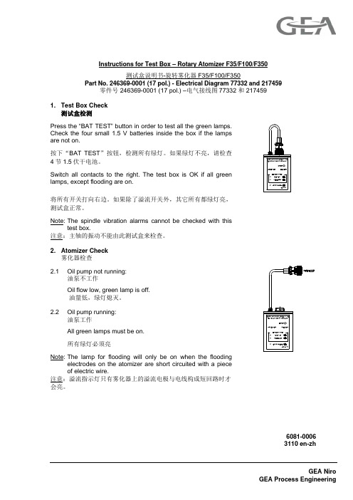
6081-00063110 en-zhGEA NiroGEA Process Engineering Instructions for Test Box – Rotary Atomizer F35/F100/F350测试盒说明书-旋转雾化器F35/F100/F350Part No. 246369-0001 (17 pol.) - Electrical Diagram 77332 and 217459零件号 246369-0001 (17 pol.) –电气接线图77332 和 2174591. Test Box Check测试盒检测Press the “BAT TEST” button in order to test all the green lamps.Check the four small 1.5 V batteries inside the box if the lampsare not on.按下“BAT TEST ”按钮,检测所有绿灯。
如果绿灯不亮,请检查4节1.5伏干电池。
Switch all contacts to the right. The test box is OK if all greenlamps, except flooding are on.将所有开关打向右边。
如果除了溢流开关外,其它所有都绿灯亮,测试盒正常。
Note: The spindle vibration alarms cannot be checked with thistest box. 注意:主轴的振动不能由此测试盒来检查。
2. Atomizer Check雾化器检查2.1 Oil pump not running:油泵不工作Oil flow low, green lamp is off.油量低,绿灯熄灭。
2.2 Oil pump running:油泵工作All green lamps must be on.所有绿灯必须亮 Note: The lamp for flooding will only be on when the floodingelectrodes on the atomizer are short circuited with a pieceof electric wire. 注意:溢流指示灯只有雾化器上的溢流电极与电线构成短回路时才会亮。
命令者三翼雾化器操作指南说明书

Operating InstructionsThe Commander Tri Jet Fogger is very user friendly for commercial or residential use. The first thing you want to dowhen you remove the unit from the box is to make sure the power switch is in the off position and the intake filter is clean and on the rear of unit to prevent damage to motor. After choosing the product you are going to spray remove tank from unit byreleasing the four tank clamps. Make sure to follow ALL guidelines from the manufacturer of Array the product that will be used. Always wear proper safety equipment when in use. Fill tank todesired amount making sure not to over fill tank. Reattach tank to unit making sure rubbergasket is in place to prevent spillage and plug into proper power supply. When you are readyto start fogging turn unit on and adjust flow valve to desired spray amount making sure not toover fog which will cause damage to motor. When you are done fogging turn unit off andunplug from wall. Empty tank of any product that may have not been used and wash out withfresh water. Fill tank with warm fresh water and little detergent and reattach to unit and let runfor few minutes outside to insure there is no product left in fogger this will prolong the life ofyour Commander Tri Jet Fogger. Always clean and dry intake filter after each use. When unitis clean, place back into box to protect from damage when not in use.The Com mander “Tri-Jet” Fogger should only be used with approved chemicals. Always follow manufactures recommendations.Operator SafetyThe operator should always wear proper protective equipment. Always wear gloves and use a measuring cup when you are mixing a product to be fogged. Always wear eye protection while fogging. After fogging any chemical containing hazardous ingredients, provide complete ventilation. Various products have differing safety precautions. Always refer to the Material Safety Data Sheet (MSDS) for specific precautions. Do not expose to rain and store in doors. Do not spray towards open flame.WarrantyYour NEW COMMANDER “TRI JET” FOGGER comes w ith a full 5 year warranty. The warranty covers against any defect inmaterial and workmanship for 5 years from date of purchase. This warranty does not apply to damage resulting fromaccidental damage, alteration to unit, misuse or abuse of fogger. Warranty does not cover damage due to over fogging. For repair or replacement please return unit back to CREATECH USA. For warranty to become effective, the information below must be supplied and faxed or mailed to CREATECH USA within 10 days of purchased date.-------------------------------------------------------------------------- DETACH ----------------------------------------------------------------------- PurchaserAddress City State Zip_________ Phone # ( ) - Model 672-120VDate of Purchase / / Model 672-220VPurchased fromAddress purchased from City State ZipUse of fogger------------------------------------------------------------------------------------------------------------------------------------------------------------------CREATECH USA INC. 1508-1 Capital Circle S.E. Tallahassee, FL 32301Tel: 850-421-6002 Fax: 850-421-6003Email: *********************。
工业门用微波红外二合一传感器说明书
12Ti 警告:不遵守适用的说明以及不当地操作设备都可能导致严重或致命的伤害。
警告:不遵守适用的说明以及不当地操作设备都可能导致人身伤害和/或财产损失。
注意:请特别注意带有此符号的部分。
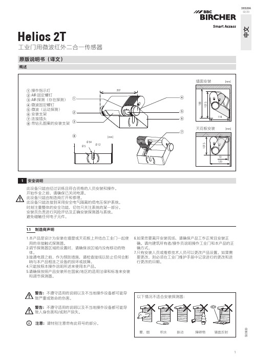
工业门用微波红外二合一传感器原版说明书(译文)概述1安全说明中文395520A 02/20此设备只能由经过训练且符合资格的人员安装和操作。
开始作业之前,请确保已关闭电源。
此设备只能由制造商打开和修理。
此设备只能连接到采用安全电气隔离的低电压保护系统。
时刻注重整体的安全功能,切勿只关注系统的某一部分。
安装员负责进行风险评估及正确安装探测器与系统。
避免碰触任何电子元件。
1.1 制造商声明1. 本产品是设计为安装在墙壁或天花板上并结合工业门一起使用的非接触式探测器。
2. 调节探测器区域的设置时,请确保该区域内没有移动的物体。
3. 接通电源之前,作为预防措施,请检查接线以防止任何会影响与本产品相连之设备的损坏或故障。
4. 只能按照本操作说明所述来使用本产品。
5. 请确保按照产品安装所在国家/地区的适用法律和标准来安装和调节探测器。
6. 如果您要离开安装现场,请确保产品工作正常且安装正确。
请向建筑所有者/操作员说明操作工业门和本产品的正确方式。
7. 只有安装人员或维修技术人员可以更改产品设置。
如果需要更改,则必须在工业门维护手册中记录进行的更改和进行更改的日期。
592883021234[mm]iGoogle Play 和 Google Play 徽标是 Google LLC 的商标。
App Store 是 Apple Inc. 的服务标志。
*B luetooth ® 文字标志和徽标是 Bluetooth SIG, Inc. 拥有的注册商标,BBC Bircher AG 对此类标志的任何使用均已获得许可。
使用 App 之前一旦使用此移动 App ,即表示您同意指定的授权和数据隐私政策,并同意使用智能手机/平板电脑定位信息和 Bluetooth* 功能。
微雾分离器与预滤芯系列AMH说明书
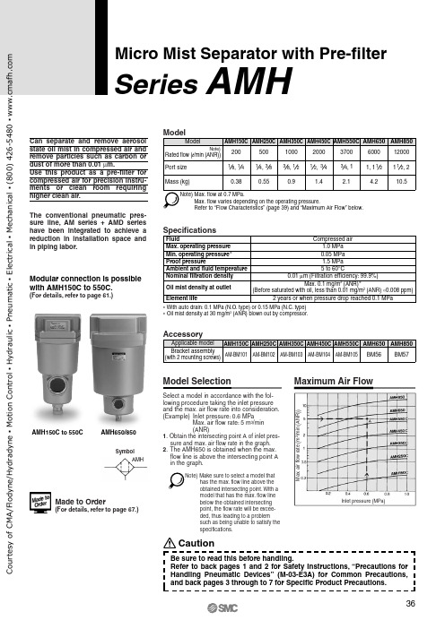
SymbolAMHM a x . a i r f l o w r a t e (m 3/m i n (A N R ))Inlet pressure (MPa)Micro Mist Separator with Pre-filterSeries AMHCan separate and remove aerosol state oil mist in compressed air and remove particles such as carbon or dust of more than 0.01 μm.Use this product as a pre-filter for compressed air for precision instru-ments or clean room requiring higher clean air.The conventional pneumatic pres-sure line, AM series + AMD series have been integrated to achieve a reduction in installation space and in piping labor.Note) Max. flow at 0.7 MPa.Max. flow varies depending on the operating pressure.Refer to “Flow Characteristics” (page 39) and “Maximum Air Flow” below.Specifications0.05 MPa 1.5 MPa FluidMax. operating pressure Min. operating pressure ∗Proof pressureAmbient and fluid temperatureNominal filtration densityElement lifeCompressed air1.0 MPa 5 to 60°C 0.01 μm (Filtration efficiency: 99.9%)Oil mist density at outletMax. 0.1 mg/m 3 (ANR)∗(Before saturated with oil, less than 0.01 mg/m 3 (ANR) ≈0.008 ppm)2 years or when pressure drop reached 0.1 MPa ∗ With auto drain: 0.1 MPa (N.O. type) or 0.15 MPa (N.C. type)∗ Oil mist density at 30 mg/m3 (ANR) blown out by compressor.Maximum Air FlowModel SelectionSelect a model in accordance with the fol-lowing procedure taking the inlet pressure and the max. air flow rate into consideration.(Example) Inlet pressure: 0.6 MPaMax. air flow rate: 5 m 3/min (ANR)1. Obtain the intersecting point A of inlet pres-sure and max. air flow rate in the graph.2. The AMH650 is obtained when the max. flow line is above the intersecting point A in the graph.Modular connection is possible with AMH150C to 550C.(For details, refer to page 61.)AMH650/850AMH150C to 550C Made to Order(For details, refer to page 67.)Note)Make sure to select a model thathas the max. flow line above the obtained intersecting point. With a model that has the max. flow line below the obtained intersecting point, the flow rate will be excee-ded, thus leading to a problem such as being unable to satisfy the specifications.CautionBe sure to read this before handling.Refer to back pages 1 and 2 for Safety Instructions, “Precautions for o u r t e s y o f C M A /F l o d y n e /H y d r a d y n e ▪ M o t i o n C o n t r o l ▪ H y d r a u l i c ▪ P n e u m a t i c ▪ E l e c t r i c a l ▪ M e c h a n i c a l ▪ (800) 426-5480 ▪ w w w .c m a f h .c o mHow to OrderOptionsSeries AMHo u r t e s y o f C M A /F l o d y n e /H y d r a d y n e ▪ M o t i o n C o n t r o l ▪ H y d r a u l i c ▪ P n e u m a t i c ▪ E l e c t r i c a l ▪ M e c h a n i c a l ▪ (800) 426-5480 ▪ w w w .c m a f h .c o mHow to OrderCombinations”.∗3Body size 850 is equipped with a ball valve(Rc3/8 female threaded). Mount a piping adapter IDF-AP609 (page 62) to the ball valve if NPT3/8 female threaded is required.: Available Micro Mist Separator with Pre-filter SeriesAMHo u r t e s y o f C M A /F l o d y n e /H y d r a d y n e ▪ M o t i o n C o n t r o l ▪ H y d r a u l i c ▪ P n e u m a t i c ▪ E l e c t r i c a l ▪ M e c h a n i c a l ▪ (800) 426-5480 ▪ w w w .c m a f h .c o mAMH150C AMH250CAMH450CAMH850AMH550CAMH350CAMH650Note) Compressed air over max. flow line in the table below may not meet the specifications of the product.It may cause damage to the element.P r e s s u r e d r o p (M P a )Air flow rate (l /min (ANR))P r e s s u r e d r o p (M P a )Air flow rate (l /min (ANR))P r e s s u r e d r o p (M P a )Air flow rate (l /min (ANR))P r e s s u r e d r o p (M P a )Air flow rate (l /min (ANR))P r e s s u r e d r o p (M P a )Air flow rate (l /min (ANR))P r e s s u r e d r o p (M P a )Air flow rate (l /min (ANR))P r e s s u r e d r o p (M P a )Air flow rate (m 3/min (ANR))Flow Characteristics /Select the model taking the max. flow capacity into consideration. ( Element oil saturation Initial condition)Inlet air pressureInlet air pressureInlet air pressureInlet air pressureAir pressureAir pressureAir pressureSeries AMHMax. flow lineMax. flow lineMax. flow lineMax. flow lineMax. flow lineMax. flow lineMax. flow lineo u r t e s y o f C M A /F l o d y n e /H y d r a d y n e ▪ M o t i o n C o n t r o l ▪ H y d r a u l i c ▪ P n e u m a t i c ▪ E l e c t r i c a l ▪ M e c h a n i c a l ▪ (800) 426-5480 ▪ w w w .c m a f h .c o mAMH150C to 550C, AMH650AMH850∗ Refer to back page 6 for replacement of auto drain.∗ Element assemblies for Made to Order (X6, X12, X15, X17, X20, X26, X37) are same as those for standard (see the above table).∗ The AMH850 is aluminum casted.ConstructionNote) Sight glass is indicated in the figure for easy understanding ofcomponent parts. However, it differs from the actualconstruction. Refer to dimensions on pages 41 through to 43 for details.OUTINMicro Mist Separator with Pre-filter SeriesAMHo u r t e s y o f C M A /F l o d y n e /H y d r a d y n e ▪ M o t i o n C o n t r o l ▪ H y d r a u l i c ▪ P n e u m a t i c ▪ E l e c t r i c a l ▪ M e c h a n i c a l ▪ (800) 426-5480 ▪ w w w .c m a f h .c o mAMH150C to 550CC: With auto drain (N.C.)D: With auto drain (N.O.)OptionJ: Drain guide 1/4 female threadedCombination of D: With auto drain (N.O.) S, U: With differential pressure switch (with indicator)T: With element service indicatorSeries AMHDimensionso u r t e s y o f C M A /F l o d y n e /H y d r a d y n e ▪ M o t i o n C o n t r o l ▪ H y d r a u l i c ▪ P n e u m a t i c ▪ E l e c t r i c a l ▪ M e c h a n i c a l ▪ (800) 426-5480 ▪ w w w .c m a f h .c o m18076853216015020154.512136160402533341011311205537M a i n t e n a n c e s p a c eDrain(Accessory)Bracket AMH650T: With element service indicatorAuto drainD: With auto drain (N.O.)OptionJ: Drain guide 1/4 female threaded201/4 female threaded34Drain cock: Blackø10 one-touch fittingDimensionsMicro Mist Separator with Pre-filter SeriesAMHINOUTIN OUTo u r t e s y o f C M A /F l o d y n e /H y d r a d y n e ▪ M o t i o n C o n t r o l ▪ H y d r a u l i c ▪ P n e u m a t i c ▪ E l e c t r i c a l ▪ M e c h a n i c a l ▪ (800) 426-5480 ▪ w w w .c m a f h .c o mM a i n t e n a n c e s p a c e22011012042220180246181842201315303484641046158Rc 3/8 female threadedAMH850Auto drainD: With auto drain (N.O.)for AMH850T: With element service indicatorOption233/8 female threadedDrainBracket (Accessory)DimensionsSeries AMHIN OUTINOUTo u r t e s y o f C M A /F l o d y n e /H y d r a d y n e ▪ M o t i o n C o n t r o l ▪ H y d r a u l i c ▪ P n e u m a t i c ▪ E l e c t r i c a l ▪ M e c h a n i c a l ▪ (800) 426-5480 ▪ w w w .c m a f h .c o m。
Aerogen Pro 雾化器系统说明手册说明书

• Aerogen Pro 需要采取电磁兼容 (EMC) 方面的特殊预防措施,并且必 须根据《使用说明》中提供的 EMC 信息进行安装和使用。
1. Aerogen Pro 雾化器装置
2. 带塞子的 T 型接头(成人)
3. 儿童T型接头及硅胶塞(选配)
4. 新生儿T型接头及硅胶塞(选配)
5. 控制器
6. 控制器电缆
7. AC/DC 适配器 4
8. 固定挂架 Aerogen Pro 雾化器系统说明手册
9. 标准挂架
10. 新生儿接头组合 (包含: 接头1: 15 M 10 mm OD -选配 接头2: 15 F,10 mm OD,7.5 mm ID-选 配)
表格列表
表 1: Aerogen Pro 雾化器系统符号...................................................... 10 表 2: Aerogen Pro 雾化器控制器和指示灯........................................... 13 表 3: Aerogen Pro 雾化器系统故障排除............................................... 34 表 4: Aerogen Pro 雾化器系统部件列表............................................... 37
注意:本设备被归类为 II 类、BF 型连续运行的医疗电子设备并符合指定 的电气绝缘和电流泄漏的安全等级。Aerogen Pro AC/DC 适配器不带接 地连接,因为通过使用双重绝缘已经达到所要求的保护级别。
MW 8100便携式焊接烟雾净化器用户维护手册说明书
USER MAINTENANCE MANUALMW 8100 Portable Welding Fume Extractor 110VWe thank you for having purchased one of the products of its range and invite you to read this booklet carefully. In it you will find all the information necessary for proper use of the machine that you have bought. For this reason, we recommend you read it throughout and to follow carefully the instructions and warnings contained therein.Make sure that you keep this booklet in a suitable clean and dry place so that it will remain undamaged. We reserve the right to modify the content of this manual, without any prior notice and without any obligations on its own part, to include any variations and improvements to the units already supplied. The reproduction or translation of any part of this booklet without prior written authorization from the manufacturer is strictly forbidden.G ENERAL I NDEX:GENERAL INDEX: _____________________________________________________________ 21. INTRODUCTION ____________________________________________________________ 32. TECHNICAL CHARACTERISTICS ____________________________________________ 3 2.1T ECHNICAL DATA ___________________________________________________________ 32.1.1 Highest Efficiency _______________________________________________________ 32.1.2 Low Noise Level ________________________________________________________ 32.1.3 Handiness _____________________________________________________________ 3 2.2W ORKING MODE ____________________________________________________________ 42.3O VERALL D IMENSIONS _______________________________________________________ 53. GENERAL USE AND SAFETY DIRECTIONS ___________________________________ 53.1U SE D IRECTIONS ____________________________________________________________ 64. PRELIMINARY CHECKS AND INSTALLATION ________________________________ 65. MAINTENANCE _____________________________________________________________ 8 5.1R EPLACING THE CARTRIDE F ILTER ______________________________________________ 85.2R EPLACING THE F ILTER WITH A CTIVATED C ARBONS ________________________________ 86. TROUBLES AND CURES _____________________________________________________ 97. WIRING DIAGRAM _________________________________________________________ 108. DESCRIPTION OF STICKERS _______________________________________________ 109. SPARE PARTS _____________________________________________________________ 1110. CONFORMITY DECLARATION ____________________________________________ 121.I NTRODUCTIONThe machine described in this booklet is a portable welding fume extractor for extracting, filtrating and de-odorizing welding fumes for light welding operations in electronic industries and in car repairing workshops.After passing through a rotary nozzle and a flexible hose having diameter 60 mm, the polluted air reaches a filter cartridge. The final deodorization is obtained by means of a filter with active carbons.Upon delivery of the machine, make sure to check that it has not suffered any damage during transportation. Should you find that the machine is not completely intact, get in touch with our dealer immediately and do not use it.The machine must be used exclusively for the purposes for which it has been built.We decline all responsibility for any damage to persons or things resulting from improper use of the product.2.T ECHNICAL C HARACTERISTICS2.1 Technical data2.1.1 Highest EfficiencyThe high-quality filtering materials of this machine make it possible to obtain an interception efficiency of over 99%. Moreover, activated carbons remove almost all odours.2.1.2 Low Noise LevelLow noise level is possible thanks to the disposition of the inner filters and to their high absorption efficiency, and also thanks to the sound absorbent materials used in conjunction with a powerful exhauster.2.1.3 HandinessWelding fumes should always be extracted before they reach respiratory tract. Fresh and pure air is a condition that can not be given up in a salubrious working place. The solution is to extract the air where pollution takes place by means of small and easily situated extraction nozzle.The easily portable, light but reliable MW 8100 is the right solution to dealing with these fumes.2.2 Working modePolluted air is extracted by means of the nozzle (part. 1, picture 1), equipped with a magnetized base that allows its safe placing. It passes through the flexible hose (part. 2, picture 1) and reaches the machi ne inlet flange (part. 3, picture 1), when there’s a labyrinth that prevents sparks from reaching the CARTRIDE filter (part. 4, picture 1). The air flow passes the CARTRIDE filter and then the cell with activated carbons (part. 6, picture 1).Inside the machine, made up of a sturdy painted sheet steel, there is the electric motor (part. 5, picture 1). picture 1 – MW 8100 PARTSPos.Description 1 Nozzle with magnetized base 2Flexible hose 60, L=3000 mm 3Machine inlet flange 4CARTRIDE filter 5Electric motor 6Activated carbons cell 7 HandleTable 2 – MW 8100 PARTS23 4 61 7 52.3 Overall Dimensions Picture 2 – MW 8100 overall dimensions3. G ENERAL U SE A ND S AFETY D IRECTIONS• Never leave packing material (such as foam polystyrene, rivets, carton, wood and so on) within children reach, since it could be dangerous.• Before connecting the system, make sure that the connection point to the supply mains, impliesthe presence of all necessary guards as foreseen by the Standards in force; also make sure that the aforementioned connection point is compatible with the system supply mains.• This equipment is to be used solely according to the purposes for which it was expressly realized. Any other kind of use is to be considered as improper and dangerous. We are not liable for any damages due to an improper use of the equipment.• Before connecting the equipment, make sure that the ratings correspond to those of the supply mains.• Do not carry out maintenance operations when the machine is running or connected to the electric power source. During these operations make absolutely sure to disconnect the machine from the power supply line.• If the machine does not operate properly DISCONNECT IT AND LET KNOW THAT IT ’S OUT OF ORDER. Apply to our After-Sale Service for repairing it and ask for original spare parts.The non-observance of what has been mentioned above could endanger the equipment safety. • We advise the use of this machine only to responsible and duly qualified staff in areas inaccessible to children.• Should you decide not to use the equipment anymore, we recommend you to disable it by disconnecting it from the supply mains and to dismantle it according to the regulations in force in your Country.• In case of accidental fall or nasty bumps, do not use the machine and contact our After-Sale Service immediately since the equipment safety could be endangered.• Work and keep the machine in a dry and sheltered place• Do not disperse used filters in the environment but deliver them to firms specialized in removal according to regulations in force.Dimension MeasureTable 3 – MW 8100overall dimensionsMeasure Dimension A 280 mmB 342 mmC 534 mmD 60 mm• The use of the filtering unit for filtering and purifying fumes coming from operations such as deburring, linishing, grinding and for extracting inflammable vapours is forbidden3.1 Use DirectionsIn order to use the machine properly proceed as follows:1. By means of its handle (part. 7, picture 1); place the machine near the welding fumes.2. By means of its magnetized base, place the nozzle where you must extract the fumes.3. Connect the power supply cable to the external plug on the machine (picture 3);4. Connect the power supply cable to the main electric grid (after making sure that the ratings written in this booklet and on the machine correspond to those of the supply mains);5. Press the starting button placed on the machine side. When it is in the position 1, a light inside the button will show that the machine is in its ON position (picture 3);6. When suction is not needed any more press again the button (position 0). The light in the button will die out (picture 3).7. Disconnect the power supply cable from the power source and from the external plug. Place the machine where it can not cause problems to or hinder workers during their usual activities.P ICTURE 3Do not carry out any maintenance procedures when the equipment is connected to the supply mains. During this phase, we recommend you disconnect it. Machine On/Off Button Plug for connecting electric cable Fuse4. P RELIMINARY CHECKS AND INSTALLATIONWhen supplied, the machine is contained in a single packaging. The operator shall do as follows: •Unload the packaging•Carry out the unpacking•Make sure that the packaging contains all parts and that they were not damaged during transport otherwise contact our Reseller.•Place the flexible hose on the inlet flange of the machine and fasten it by means of the hose clamp.•Connect the power supply cable to the main electric grid (after making sure that the supply voltage/frequency are 110 V/50 Hz);•Use the machine as described in paragraph 3.1 Use direction.Before connecting the machine to the main electric grid,make sure that the ratings on the machine correspondthe ones of the supply mains5. M AINTENANCE Do not carry out any maintenance procedures when the machine is connected to the supply mains. During this phase we recommend you disconnect the cable form the power supply mains. For a keeping a good machine efficiency, do as follows:• Check the feed cables on a daily basis• Keep the machine in a sheltered place• Make sure that the flexible hose is not damaged in any pointHow frequently the filters are monitored will depend on the type and frequency of welding carried out. Regular testing of the extraction capacity of the machine is required, reduction in this capacity means the saturation of the cartridge filter, which will need replacing when fully saturated.5.1 Replacing the Cartridge FilterThe cartride filter is part no.4 of picture 1.1. Make sure that the machine is disconnected from the power supply mains. Then loosen the clipsof the cover (front side - reference fig. 4) and open it.2. Unscrew the blade-screw.3. Take away the bar.4. Take out the filter and insert the new one, making sure that it is well inserted.5. Replace the bar in its original position.6. Screw the blade-screw again.7. Close the cover carefully by means of its clips.5.2 Replacing the Filter with Activated CarbonsThe filter with activated carbons is the part no. 6 in picture 1.1. Make sure that the machine is disconnected from the power supply mains. Then loosen the clipsfastening the cell (back side - reference fig. 4) and take it away.2. Unscrew the four screws on the cell and replace the carbons with the new ones. Then screw thescrews again.3. Refasten the cell with the new activated carbons by means of the clips.picture 4 – Front/back sidesFront side Back side6.T ROUBLES AND C URESMake sure that the machine is switched off and disconnected from the supply mains before carrying out any maintenance or repair procedures. Make also sure that these procedures can not cause any damages to things or people.Always apply to Qualified Personnel.Troubles Causes CuresMachine fails to start up The Fuse has burnt out Check its state (it is placed nearthe star up button - picture 3)Too low voltage Check the supply mains voltageThe electric motor is mis-working Contact our After-Sale Service orprofessionally qualified staffThe emitted air is not purified enough Inefficacious action of filters Check their state and replace them(ref. to chapter 5M AINTENANCE)The machine does not develop a sufficient aspirating capacity Filters are clogged and dirty Check their state and replace them(ref. to chapter. 5M AINTENANCE) Physical obstructions and/orblockagesCheck whether there are anyforeign bodies inside the hose.Take them awayThe hose is broken or damaged Check its state and if it’s damagedreplace it.The electric motor is not working Contact our After-Sale Service orprofessionally qualified staffFuses of main electric system burn out and/or differential relay device -ground fault interrupter trips Short circuit (in electric motor) Contact our Technical Service orprofessionally qualified staff tocarry out a more precise check.ALWAYS CONSULT A QUALIFIED PERSONNEL7.W IRING DIAGRAMPicture 5 – wiring diagram8.D ESCRIPTION OF STICKERSPicture 6Sticker indicating that there are parts live inside the machine.MONOFASE110Picture 7 – single-phase motor, Voltages : 110 VSticker indicating that the electric motor is single-phase and that it has to be fed with 110 V.9.S PARE PARTSWhen ordering a spare part please refer to the model of the machine in your possession.E.G.: Refill Bag with 2 kg active carbons for portable filtration unit Model MW8100. You are recommended to use original spare parts.10.C ONFORMITY D ECLARATIONIn the person of our legal representative declares under our own responsibility that the product:PORTABLE UNIT FOR FILTRATION OF FUMESMODEL : MW 8100To which this declaration is referred, is in conformity to what prescribed in directives 2006/42/CE,2014/35/UE,2014/30/UE.We further state that:- The manufacturing year is quoted on the label (with EC mark) placed on the machine. - The serial number of the machine is quoted directly on it.MW 8100。
KROHNE OPTIFLEX 2200 C F 导波雷达物位变送器NEPSI应用补充说明说明书
导波雷达(TDR)物位变送器适合储存和过程应用对于NEPSI应用的补充说明OPTIFLEX 2200 C/F补充说明© KROHNE 12/2018 - 4005402402 - AD NEPSI OPTIFLEX2200 zh R02内容212/2018 - 4005402402 - AD NEPSI OPTIFLEX2200 zh R021 通用安全信息31.1 文档范围.................................................................31.2 仪表说明.................................................................31.3 标准和认证...............................................................31.4 设备保护等级 (EPL)和粉尘区.. (4)1.4.1 Ex ia 和 Ex iaD-认证的仪表.................................................41.4.2 Ex d ia 和 Ex iaD tD-认证的仪表.. (4)1.5 NEPSI 铭牌 (5)2 安装72.1 注意事项 (7)2.1.1 常规注意事项................................................................72.1.2 静电放电.. (7)2.2 操作条件 (8)2.2.1 环境及法兰温度..............................................................82.2.2 粉尘应用场合的壳体表面最高温度.............................................142.2.3 过程压力. (14)3 电气连接153.1 注意....................................................................153.2 接线端子腔体 (15)3.2.1 如何打开接线端子腔体.......................................................153.2.2 如何关上接线端子腔 (17)3.3 端子拧紧力..............................................................173.4 等电位连接系统..........................................................183.5 Ex ia 和 Ex iaD 设备. (19)3.5.1 如何连接电气电缆...........................................................193.5.2 电路的最大本质安全值.......................................................193.5.3 电源电压...................................................................193.5.4 电气示意图.................................................................203.6 Ex d ia 和 Ex iaD tD 设备.. (21)3.6.1 常规注意事项...............................................................213.6.2 如何连接电气电缆...........................................................213.6.3 电源电压...................................................................223.6.4 电气示意图.................................................................224 启动245 服务255.1 周期性维护..............................................................255.2 保持仪表清洁............................................................255.3 制造商..................................................................255.4 仪器送返生产厂家.. (26)5.4.1 基本信息...................................................................265.4.2 送返仪器时附带的表格(可复印) (27)1312/2018 - 4005402402 - AD NEPSI OPTIFLEX2200 zh R021.1 文档范围这些指令只适用于防爆型的TDR 物位变送器。
APF操作手册
德殷能源科技(上海)有限公司 4.4 外形及安装图 .............................................................................................................. 19
4.4.1 壁挂式外形及安装图............................................................................................ 19 4.4.2 柜式外形及安装图................................................................................................ 20 5 功能与操作界面说明 ............................................................................................................... 20 5.1 人机界面概述................................................................................................................ 20 5.2 启动画面......................................................................................................................... 21 5.3 主界面 ............................................................................................................................ 22 5.4 监控界面........................................................................................................................ 23 5.5 系统参数........................................................................................................................ 23 5.5.1 电源侧参数 ........................................................................................................... 24 5.5.2 负载侧参数 ........................................................................................................... 24 5.5.3 APF 侧参数 ............................................................................................................ 25 5.5.4 联机状态............................................................................................................... 26 5.5.5 设备参数................................................................................................................ 27 5.6 曲线显示 ......................................................................................................................... 28 5.7 参数设置 ......................................................................................................................... 29 5.7.1 补偿设置................................................................................................................ 30 5.7.2 内部参数................................................................................................................ 31 5.7.3 报警故障............................................................................................................... 35 5.7.4 LCD 设置 ............................................................................................................... 36 5.7.5 联机设置............................................................................................................... 37 5.7.6 诊断维护设置 ....................................................................................................... 38 5.8 事件记录 ......................................................................................................................... 38 5.9 操作说明 ......................................................................................................................... 39 5.9.1 上电检查................................................................................................................ 39 5.9.2 启动步骤............................................................................................................... 39 5.10 设备维护........................................................................................................................ 40 6 常见问题的处理....................................................................................................................... 41 6.1 异常处理说明.................................................................................................................. 41 6.2 常见故障处理.................................................................................................................. 42
3016中文说明书-(1)资料
Lighthouse Worldwide SolutionsHANDHELD 粒子计数器操作手册型号:3016,5016版本2.60 2011年版本Lighthouse国际有限公司1.介绍概要本操作指南描述了如何使用Lighthouse HANDHELD 3016和5016系列空气粒子计数器.这种型号数字代表了所测量的最小的粒径范围.数字“3016”表示在0.1CFM时最小的通道为0.3μm.数字“5016”表示在0.1CFM时最小通道为0.5μm.3016+和5016+型号的仪器可以达到六个粒子通道,两个环境传感器和一个彩色可触摸的界面.这种3016+和5016+型号的仪器也可以配置一个内置热敏打印机和一个标准可充电电池.(注意对于每一种HANDHELD类型的标准通道配置,可以查看这一章节的HANDHELD的参数表.)所有的HANDHELD系列仪器均包含一个微处理器来控制所有仪器的功能.数据以总量和分量模式显示为原始数据和对应每立方英尺或每立方米的粒子浓度.HANDHELD使用激光器二极管为激光光源并收集粒子反射光.粒子反射从激光管中发出来的光.这种可收集的光被收集并且集中在光电效应管上,它可以把光束转换成电子脉冲.这种脉冲可以计算并且可以根据它们的高度测量出粒子范围.结果以相应的粒径通道的粒子数显示出来.描述LIGHTHOUSE HANDHELD仪器使用最新的光学粒子检测技术.提供了当流量为0.1CFM(2.83升/分钟)时最小敏感度为0.3μm的3016/3016+产品线和最小敏感度为0.5μm 的5016/5016+产品线,HANDHELD系列提供一个最大可达25.0μm的动态粒径范围.集成了一个大的可触摸界面(3016+和5016+为彩色,3016和5016为黑白),HANDHELD系列仪器操作和设定极其简便.HANDHELD系列能存储大量数据,3016+和5016+的六个粒子计数通道和两个环境传感器的数据和3016和5016的两个粒子计数通道和两个环境传感器的数据.所有的数据能迅速且可靠的下载到计算机或者打印到它的打印机(3016和5016可选打印机,3016+和5016+内置打印机).HANDHELD系列的仪器允许你:设置采样和间隔时间设置单一位置的采样次数可外接两个环境传感器按联邦标准209E(ft3),209E(m3),EC GMP ,ISO 146441-1和英国标准5295打印报告保存历史数据使用所附送的数据转换软件打印图表或下载数据到EXCEL文件便于制图.2.打开检查和安装初始检查(注意:检查包裹外包装的震动标记;它是否为红色或者清楚?如果它为红色,表明它在运输过程中受到了震动.请确认它的功能和装置.)仪器在工厂中已完成检测和试验,并且准备签收.当收到货物时应检查包装箱是否有损坏.如果包装箱损坏,应立即通知承运商.如果包装箱损坏了,小心打开它并在使用前检测已打碎的部件,刮痕,凹陷及其它有损坏的部分.核实包装内容1.HANDHELD粒子计数器2.粒子计数器校准证书3.快速指南4.操作手册7.带胶管的0.1CFM流量0.2μm的零过滤器8.电源线9. 2个保险丝11.数据传送软件(LMS XChange)CD12.数据传送线及连接插头13. 2卷打印纸(3016+和5016+为标准配置,3016和5016为选件)如果对于上述所列有缺少,请立即与lighthouse 销售代表联系,免费电话800-945-5905.保留外包装及其它物件以便邮寄回去做仪器的年度校正.型号Lighthouse Handheld 3016最小粒直径0.3µM通道数 6标准通道0.3, 0.5, 0.7, 1.0, 2.0, 5.0µM, 流量控制0.1 CFM显示屏幕Touch Screen 1/4 VGA零顾虑器<1 / 5 minutes测量效率50%Light Source Laser Diode最大浓度@ 保证5%错误率2,000,000 Particles / Ft3 流量Internal真空泵Carbon Vane输出信号RS-232测试点0-999附件某些附件可以订货,装配仪器来满足你的要求.有些可以选择,而有些对每一个仪器是标准的.●温湿度探头(选件)------插在仪器的上部,4-20mA探头监测相对湿度(0%-100%)温度(-17.8℃-65.6℃或0-150)结果可以显示,打印,能够下载到LMS软件作为备份和历史数据查看.●标准等动力采样探头(标准件)-使用在计数和实际的粒子大小分布之间的最大关联单向气流.也可用于手持测量局部粒子计数.●过滤扫描探头(选件)-用于过滤装置的泄漏的扫描.●带轮运输箱(选件)●打印纸(对于3016+/5016+为两卷,对于3016/5016为选件)●净化间打印纸(选件,必须定购10卷或以上).●认证文件(选件)●锂电池,可移动和充电(对于3016+/5016+标准,而对于3016/5016为选件)●外置电池充电器(选件)●净化间手推车(选件)●USB串口适配器,为只有USB而无9针串行通信口的笔记本而备.●LMS软件,一种分析工具允许使用者:1.从仪器上下载数据2.保存数据作为历史数据查看3.可以打标准报告等等欲了解更详细的内容,请联系Lighthouse.安装连接电源电源输入为85-264V AC,47-63HZ.HANDHELD包括一个电源线.电源开关位于仪器的前部.推荐使用电源保护装置以防止开机时电压不足.当HANDHELD保持在固定位置时使用不间断的电源供应可以防止仪器的损坏或电源输出过程中的数据的丢失.安装电池HANDHELD3016+/5016+配有可充电的锂电池.这种可充电的电池对于3016/5016为选件.在仪器便携式使用操作前,应安装电池.开始电池可能未被冲满电.安装后应立即充电,把充电器插入AC电源并打开位于前部的电源开关.(警告:通过机器充电时,插入AC电源并打开位于前部的电源开关.)安装电池前,应确保电源开关处于关闭状态,然后遵循下列步骤;1.如图2-2,逆时针旋转锁扣打开电池舱后盖.图2-2电池箱盖4.按下连接器直到你听到咔嚓一声.5.如图2-5,下一步,把电池推入电池舱.6.将电池完全推入电池舱, 关闭舱门, 顺时针系紧螺丝, 锁住舱门.取出电池1.如图2-7,打开电池后舱盖并牵拉丝带以取出电池.2.如图2-8,当电池完全拽出后,抓住V型柄,松开电池电线,轻拽出并直到电线连线离开电池.图2-8松开连接线(警告:仪器运输前应卸掉电池.)连接一环境传感器:HANDHELD系列仪器在它的背板上有4类4-20mA的模拟输入口,针对这些口将在第三章做详细描述.可连接的模拟传感器为温度,相对湿度,风速,压差,静电,分子污染分析仪等等.每个传感器通过位于仪器后部的RJ—12连接口与HANDHELD连接.请查阅每一种传感器手册以得到正确的管脚图.连接外置电脑或设备管理系统.HANDHELD系列仪器具有连接到Lighthouse监测系统,LMS Express或LMS Xchange 数据转换软件以便下载数据.下载数据到Lighthouse监测系统(LMS)或LMS Express,你能存储历史数据,以便将来查看.在LMS Xchange,数据可以输出到a*.csv文件存储历史数据.在LMS Xchange软件和HANDHELD仪器之间有多达200个数值位置标号可以传输.这种转换通过Modbus通讯协议完成.请查阅LMS, LMS Express或LMS Xchange手册获取更多信息.3.操作这一章描述如何使用HANDHELD空气粒子计数器.这一章中的说明将以HANDHELD 3016+型号仪器的粒径通道和报告为准,除非特别说明.将HANDHELD仪器从箱子里取出,开始使用仪器,按如下步骤完成.1.把仪器放在你准备检测的地方.2.根据第二章指南装入电池.3.插上AC电源.4.从采样口处去除保护管,如果使用提供的标准等动力采样头,通过采样管连接到位于仪器顶部的入口处,装上等动力采样头.5.在前面板把电源开关置入ON位置.6.当通电后,仪器显示开始屏幕.7.显示MAIN(菜单)屏幕.8.如果准备用环境传感器,把它们插入到仪器的背板上.Lighthouse出售的一种4-20mA温/湿度棒可直接连到口1和3.温度数据在位置1或3显示,湿度数据将在位置2或4显示.9.在触摸屏上,按下START/STOP按钮开始启动仪器.10.当采样泵最初打开后,STARTING将显示.11.当计数开始,COUNTING将开始显示,测试结果根据每一粒子的大小显示出来.12.如果设置了采样间隔,在每一采样结束后显示HOLDING,当所有样本完成后显示FINISHED.13.如果在所有检测完成前你想停止,则按下STOP/STOP按钮.如果按下了STOP键,“STOPPED”字样将显示以表明采样是在未完成时停止的.(警告:a.不要试图用该仪器采样能起化学反应的几种气体,例如氢气和氧气.起反应的气体能给仪器带来爆炸的危险.)b.直接采样高压下的任何气体将会损坏仪器.c.如果所采气体与环境空气的密度不一样可能会导致结果不正确.注意:泵的马达需要5秒钟达到1CFM.“STARTING”时间包括这5秒钟的时间.警告:a.为了防止损坏仪器,水,溶剂和其他任何类型的液体都不能通过采样口进入仪器.b.采样管防尘帽盖在上面或堵住的时候不能开启仪器,否则会损伤内部泵.)触摸屏概要HANDHELD系列仪器集成了独特的可触摸屏来控制和设定仪器.增强型有(+)配有彩色触摸屏,基本型号采用单色触摸显示屏.此界面允许使用者方便地操作和应用,所有功能均可通过触摸屏来访问.*如果设置了开机密码**如果设置了配置密码主菜单主菜单提供了使用者对仪器功能状态的快速查看, 仪器可通过AC电源或内部可移动的电池来供电,(针对(+)号仪器;对基本型号为选件),电池显示将会显示电池的容量.图3-1主界面---电池供电图3-2主界面---市电供电AC显示符号显示从AC电源获得能量.LOCATION: 显示正在测量的区域.每台仪器可以设定多达200个区域标记.LOCATION选择按钮:允许用户在采样开始之前改变区域标记.LOCATION+/-按钮:当仪器开始计数时LOCA TION选择键和按钮变成+和-按钮.这?样允许用户在采样间隔内增减位置标记.ABOUT按钮:显示仪器版本号和仪器型号.ALARM ACKNOWLEDGE按钮:当任何通道粒子满足报警条件时,HANDHELD仪器会在采样过程中每秒产生鸣叫.按下Alarm Acknowledge按钮会让余下的采样时间内不产生鸣叫.如果仪器连接了外置的报警灯或蜂鸣器,按下Alarm Acknowledge按钮会在余下的采样时间内关闭报警灯或蜂鸣器.PRINT LAST RECORD:使用当前配置以当前的数据格式打印最后一个保存的数据(即是独立值对累加值,原始值对浓度值,立方英尺对立方米).打印设置是在PRINT SETUP 菜单下CONFIGURATION页面来完成的.更详细内容会在本章节的CONFIGURATION小节阐述.Date/Time:显示当前时间,日期.Battery indicator:显示仪器正在使用可充电电池电源,电池容量通过电池符号来显示,当电池耗损时,在屏幕上会显示“BATT LOW”字样.仪器会连续报警直到插入外接AC电源给予充电.(注意:如果在仪器的采样过程中电池指示标记出现“×”内部流量泵会自动停止以防止电池彻底放电.如果发生该情形,请外接市电并确保前面板上的电源开关是打开的.完全充满电需要4-5个小时.仪器在充电过程中你可以继续运行采样.)AC Indicator: 当插入AC电源时,AC显示会出现,表明仪器正由市电供电,此时如果接有电池将会给电池充电.Flow Status: 当仪器在采样时,流量状态指示会显示流量充足或不足.Service indicator:如果仪器需要被清洁或保养,Service显示开始.DA TA DISPLAY: 这将显示所测粒子是以独立值(Diff)或累加值(Cuml)显示,如果所测粒子显示是浓度值,将会表明是每立方英尺或每立方米.Analog Data:如果外接模拟传感器并且被激活了,该项将对前2个通道的数据提供一个快速浏览的方法.MODE:显示当前选择模式,可能的模式有AUTO自动,MANUAL手动, Concen浓度, BEEP报警两种模式.CYCLES:显示在自动模式下设定的采样次数的数量.如1/3表示这个计数是在为该区域要取样的3个样本中的第一个采样数据.最大周期次数为999.当设置为0时,仪器将按自动模式工作直至按下STOP按钮.SAMPLE TIME:时间(时:分:秒)是一次计数循环周期,当仪器处于自动或手动模式时,显示在主屏上的采样时间会递减,这样你就知道采样还剩多少时间.在浓度模式时,每个样本会计数到6秒.HOLD TIME: 显示二次周期之间的间隔时间,最大间隔时间为99小时59分59秒.(注意:如果间隔时间大于1分钟,在这段时间内泵会自动停止.在间隔时间快完时泵会自动开启.)RECS:显示储存在仪器中的采样记录的数量和可存储在仪器内的总数量.数据存储区是一个循环的缓冲器.当新数据存储在已满的区域时会在前面出现一个星号.+型号可以存储3000组数据,普通型号可以存储1500组数据.START/STOP:按下屏幕左下方的START按钮开始计数.当仪器工作时,在屏幕的右下角“REPORTS”按钮上面将会显示“COUNTING”字样.按下STOP按钮停止计数,“STOPPED”字样将会出现.图3-4计数模式(注意:从启动开始流量泵需要5秒钟的时间才能达到满负荷,在这段时间内“STARTING”字样将会出现.)Changing Locations当要为准备采样的样本更换区域标记时,你可以通过在屏幕上方按下LOCATION键来实现.这将显示一个界面让你选择一个新的区域标记.使用上下键来选择.单个的上下键会逐行移动.双键会显示上或下10个数据块.三键会跳到上或下的100个区域.这便于查找.图3-6箭头按下MAIN按钮将会回到主画面.当前选中的任何一个区域标记将会在主画面显示.图3-7新选中的区域标记Locations and AUTO Mode当仪器为自动模式时,START按钮被按下,仪器会根据已经设定的采样时间,间隔时间和循环周期等参数开始自动计数.当仪器显示为HOLDING时,你可以使用+和-按钮来改变数据存储的位置标记.例如:如果你想采样二个不同位置,二个位置之间需要步行5分钟.把你的间隔时间设为5分钟,在第一个周期从位置1采集数据,然而当仪器对第一周期结束计数时,在HOLDING5分钟内,调整到位置2,并移动仪器到第二个位置,你的仪器将位置1数据存为第一个记录,位置2数据存为第2个记录.图3-8使用+和-来改变区域标记当仪器结束COUNTING并进入HOLDING状态,数据将被保存到显示的位置处.区域标记名称可以用Configuration菜单下的Location编辑功能来实现.区域标记名称可以由8位的数字、字母和下划线构成.欲了解详细内容可以参见后面章节. Zoomed Data View在粒子数据显示的任何区域按压都会放大屏幕.如图3-9.图3-9放大数据显示在该页按压右边的工具条可以实现如下功能:开始/结束采样显示粒子/模拟数据显示累加/独立粒子数显示原始/浓度粒子数打印最后一组保存数据(只有仪器处于STOPPED和HOLDING状态时才能完成两种状态之间的切换.)当仪器在STOPPED和HOLDING状态时,在白的数据显示区域内按压任何一个地方都会返回到主画面.Data Setup: 包括设置粒径通道,模拟通道,样本存储参数,采样设置,报警使能和报警门槛以及清空缓存.Device Setup: 包括设置仪器的日期和时间,LCD对比度,仪器嗡鸣声响度,调整触摸屏,使能自启动,通信地址,区域标记名称,密码限制,打印设置和浏览仪器当前参数.Data Setup粒径通道可以在如图3-11页面进行设置.绿色的对号表示显示该通道.绿色的对号是切换键.按下一次不显示该通道,并且还出现一个红色的“×”以表明该通道被废止了.再次按下该键又会变成对号并使能该通道.按下MAIN或BACK将会提示清空所有存储的数据.(注意:当粒径通道被使能或废止时将会清空数据存储区,这样在存储区里的数据就会有相同的通道数.)图3-12清空数据界面如图3-12按下CANCEL键会取消设置并退回CONFIGURATION画面.当通道被废止后,它们将不会在主画面、报告、打印输出上出现.被废止的通道在数据存储区依然存在,但在这些通道将不会记录数据.模拟通道可以指定一个型号(4位)如图3-14和它的测量单位(4位)如图3-15.图3-14设定模拟型号图3-15设定模拟单位按下最小值键来输入数据下限,按下最大值键来输入数据上限.图3-16最大值、最小值设定界面当设备不在计数或处于两次采样中间的待机时段内,按压粒子数据显示区域的任何位置都会放大画面,然后如图3-18所示切换到显示模拟传感器数据的画面.图3-18放大的数据浏览区:模拟数据采样定时和采样样本数在如图3-19的页面进行设置.CYCLES:设置采样循环次数来定义在该位置仪器采样几次.这仅仅应用于自动模式里.可以设置0-999次.当采样次数设为零时,仪器会一直运行直到按下停止键.选择CYCLES按钮,用右边的数值键盘来输入采样次数,按下回车键完成设置.DELAY:初始延迟时间(时:分:秒)是按下启动键和泵实际开始运行之间的时间段.这给操作人员一定时间来离开将要进行测试的区域来确保测试是在受控的条件下进行的.最长延迟时间是99小时59分59秒.选择DELAY按钮用右边的数字键盘输入时分秒,按下回车键完成设置.HOLD:间隔时间(时:分:秒)是在采样之间的仪器待机时间.设定方法同采样时间一样.最长间隔时间是99小时59分59秒.这里是递减来显示待机时段还剩下多少时间.选择HOLD按钮用右边的数字键盘输入时分秒,按下回车键完成设置.(注意:如果在自动模式里将间隔时间设为0:00:00,仪器将会按照预设的采样时间和采样次数运行,但在采样之间不会待机.如果间隔时间大于1分钟,在待机时间内泵会停止运行.当泵在再次运行的时候,在采样开始之前它将需要5秒钟来达到1CFM的流量.)SAMPLE:采样时间(时:分:秒)是采样计数的时间段.当仪器处于自动模式和手动模式下采样,在主画面该时间递减,这样你就很直观地知道还剩多少时间.选择SAMPLE按钮用右边的数字键盘输入时分秒,按下回车键完成设置.VOLUME:除了直接设置采样时间外,你还可以通过设定立方英尺、立方米、升来确定样本量.当该项被设置后采样时间自动更新了.(注意:当以升来衡量采样体积大小时,最大可以取样的体积是9999.99升,相应的采样时间是05:53:08.当以立方英尺和立方米为量纲时,最大的采样时间是23:59:59分别对应1439.983立方英尺和40.776立方米.对于1cfm的仪器,如果最小采样体积是0.001立方米对应的采样时间是2秒.).按下BACK键回到CONFIGURATION画面或按下MAIN回到主画面图3-21计数模式COUNT MODE如下两种模式可选:自动、手动、鸣叫、浓度.AUTO------:当仪器在自动模式时,START按钮按下后,仪器根据采样时间,间隔时间及设置的循环次数自动计数.如果循环设为0,则仪器自动计数直至STOP按钮按下为止.MANUAL-------:当START钮按下后开始计数,在程序控制的采样时间段结束后停止.CONC(Concentration Mode)------:当仪器在Concentration模式下,它给出在一定空气量的粒子浓度值,并以每立方英尺或每立方米为单位显示在主界面上.当你按下START时开始计数,直到再次按下STOP结束.测量数值及显示每6图3-20改变采样体积单位秒更新一次.BEEP报警模式:在这种模式下,仪器根据设置值来报警.当你按下START钮计数开STOP钮结束.如果通道大小未选择,BEEP报警模式将自动选择最小的通道报警而不管是否设置该值.(小技巧:鸣叫模式可以用来检漏,报警门槛值设为1,模式设为BEEP模式.注意:BEEP模式只对累加值起作用.)PARTICLE DISPLAY仪器的数据可以以独立值DIFF和累加值CUML形式显示.对于lμm通道累加值,是该通道的总数加上2.5μm通道数据和5μm数据的总和.对于lμm通道独立值,是在lμm和2.5μm通道之间的粒子数.主页面的数据是根据选定的格式来显示的.数据格式可以是原始数据或标准浓度值.原始数据是粒子计数的实际数,Norm数据是根据选定的单位立方英尺或立方米而从原始数据计算出来的粒子浓度.空气容积=采样时间(分)×流量速率(cfm)标准数据=粒子数/空气容积按下BACK键回到CONFIGURATION画面或按下MAIN回到主画面..Alarm Threshold按通道序号后面的门槛值可以设置对应通道的报警门槛.如图3-23.图3-23设定报警门槛值要清仪器的数据存储区按清除按钮.如图3-27所示按OK键清空所有数据,按Cancel键退出该屏而不清数据.图3-27 清数据存储器界面DEVICE SETUP仪器的日期和时间在如图3-28的界面设置.图3-28日期和时间设置界面日期的设置通过输入月,日,年后按回车键完成.日期的显示可以以月份排在最前面.这是缺省设置.日期的显示也可以以日排在最前面.图3-29日期选项:日排第一位日期的显示也可以以年份排在最前面.图3-30日期选项:年排第一位时间的设置按TIME键.图3-31设定时间时间的设置通过输入小时,分,秒后按回车键完成.按下BACK键回到CONFIGURATION画面或按下MAIN回到主画面.(警告:请仅按指定的位置.如果在该过程中按别处,将会错误地调整它.)·如图3-33屏幕出现.图3-33屏幕调整步骤1·按位于左下角的圆圈.(注意:使用PDA输入笔将使屏幕界面调整更精确.)·然后按位于与右上角的圆圈.图3-34屏幕调整步骤2·在校正屏,按压屏幕上几个不同位置.你所触摸的每一个位置有“X”显示表明这种调整成功.图3-35验证触摸屏阵列·按屏幕中心上矩形中的任一位置来完成调整.·调整完成后关闭电源开关.等几秒以后再打开电源.Alignment At Startup你也可以通过先关闭电源然后用一根手按住触摸屏再打开仪器来访问屏幕调整界面.这将显示如图3-36所示界面.图3-36在开机时调整(注意:如果在仪器的正常使用过程中按压工具条没反应或不起作用,关掉仪器,然后在屏幕变成空白以后再打开.)·如前面所描述过程继续.·当调整完成后,关闭电源再开机.当仪器连接到数据采样系统或串接到其它RS-485仪器上时,通信地址是用来识别仪器的.LMS Xchange和LMS Express RT/RT+软件将会在你指定的通信地址上寻找仪器.范围是01—63.对于RS-485通信,多通道串接链上的每一个设备都必须有一个唯一的地址.图3-37通信地址设置界面用内置的数字键盘输入相应的通信地址,再按回车键.按下BACK键回到CONFIGURATION画面或按下MAIN回到主画面.你可以设置数字字母标识的200个不同的区域标记.在如图3-38所示的区域标记设置页面,用上下键选择你要改变的名称.图3-38区域标记选择界面按下EDIT键会出现如图3-39的界面.图3-39区域标记编辑界面用数字字母键盘和下划线来输入新的区域标记的名称.如果输错了,用ERASE键删除输入的最后一个字母.输入回车键.用箭头来选取你想编辑的下一个区域标记再按编辑键.如此方法可以编辑任意你想要改变的区域标记名称.按下BACK键回到CONFIGURATION画面或按下MAIN回到主画面.该仪器可设置两级不同的密码权限.设置开机密码,选择POWER ON工具条,然后用数字键盘输入密码.如果输错了按清除.按回车键保存.设置系统设置密码,选择CFG工具条,然后用数字键盘输入密码.如果输错了按清除.按回车键保存.按下红色的“×”号来使能任意一个或两个密码设置功能.按下BACK键回到CONFIGURATION画面或按下MAIN回到主画面.POWER ON PASSWORD如果设置了开机密码,在开机时要求输入密码.当你开机以后会看到如图3-41所示界面.图3-41开机密码访问界面仪器将被一直锁住直到你输入了正确的密码.(警告:请把你的密码保存在一个安全的位置.如果忘记了请致电Lighthouse技术支持寻求帮助.)CONFIGURATION PASSWORD系统设置密码防止未被授权的访问.图3-40密码设置界面图3-42仪器配置密码访问界面在主界面按DATA键将会浏览数据存储器.依据采样设置,数据将会以原始数据或对应ft^3或m^3的标准浓度值显示.(注意:利用右侧的上下键翻页查阅数据.单键一次滚动一个记录.双键一次移动10个数据.三键一次移动100个数据.当数据存储器的数据发生了覆盖,第一个显示的数据是数据存储器的第一个记录但并不是第一个测试点的值.如果正显示第一个记录,你按下键一次,它翻到最后一个记录.)图3-49浏览数据界面---原始数据图3-50浏览数据界面---标准浓度值(ft³)。
- 1、下载文档前请自行甄别文档内容的完整性,平台不提供额外的编辑、内容补充、找答案等附加服务。
- 2、"仅部分预览"的文档,不可在线预览部分如存在完整性等问题,可反馈申请退款(可完整预览的文档不适用该条件!)。
- 3、如文档侵犯您的权益,请联系客服反馈,我们会尽快为您处理(人工客服工作时间:9:00-18:30)。
高压微雾设备说明书首先非常感谢贵方使用本公司的产品。
本公司研发的高压微雾设备能够为广大用户提供多种规格配置及全面的定制化服务,特别针对用户在选购传统加湿设备时面临的投资大、运行成本高、维护工作量大等缺点以及要求在特定环境加湿的特殊需求得以解决。
本公司的高压微雾设备可根据客户需求,集成多个工作控制系统,包括恒压供水系统、缺水保护系统、水质过滤系统、温湿度多路控制系统、电机综合保护系统、自动排水系统、水加热系统。
温湿度多路控制系统,可以精确控制多个单元区域的温湿度,以满足用户不同生产工序对温湿度的要求。
水加热及电气控制系统,可以保证用户在低温时系统良好的出雾工作状态。
本公司的高压微雾设备具有良好的集成性以及配套的安装售后服务,使用方便性能高,特别适合造纸、房地产、化工、纺织化纤、电子制造、畜牧养殖、食用菌食品、印刷、烟草、煤矿等各个行业及需要加湿、恒湿、造雾的空间。
我们将以良好的企业信誉,积极完善的售前、售中、售后服务体系及多元化的微雾系统工程解决方案竭诚为您服务。
高压微雾系统操作指南目录一、主机安装………………………………………………………………………………………二、试机操作说明…………………………………………………………………………………三、常见故障及其解决方法………………………………………………………………………1.常见故障………………………………………………………………………………………2.控制系统故障…………………………………………………………………………………3.湿度显示故障…………………………………………………………………………………4.主机振动………………………………………………………………………………………四、操作维护保养…………………………………………………………………………………1.高压水泵………………………………………………………………………………………2.高压电磁阀……………………………………………………………………………………3.喷头清洗………………………………………………………………………………………4.水过滤器………………………………………………………………………………………五、技术规格和参数………………………………………………………………………………六、服务承诺………………………………………………………………………………………一、主机安装1.主机须安置于室内或有遮盖的场所以免日晒雨淋。
远离热源,四周0.5米范围内不要堆放杂物或存在障碍物,确保良好的通风,以防主机内部散热不良。
(电器元件的环境要求:湿度:小于85%,温度:0-50℃)。
2.主机箱须水平放置以利于各处的润滑和各连接部件的受力,防止噪音和震动增大。
3.电器及主机箱必须安全接地,以防触电。
二、试机操作说明及注意事项1.先打开机组箱体,检查电气接线端子有无松动或脱落,以防在运输过程中线头松动或脱落造成短路故障。
2.检查高压水泵各部分分管路有无松动,水泵是否缺油,确认后向机组水箱注水,水满后请检查水箱是否有渗漏现象。
3.连接好三相四线电源进线。
(电机正反转都可以正常工作)4.合上小型断路器,检查电源指示灯是否工作。
5.先把手动/自动旋钮开关扭向手动位置,看高压泵是否能直接启动,看工作指示灯是否工作。
6.在手动工作时,请调整水泵工作压力,使之符合用户自己的要求。
7.调整湿度控制器,设定好车间加湿喷雾上-下限湿度合理参数(详见湿度控制器使用说明,有的湿度控制器带温度、时间控制,视工程需求而定)8.设定完毕后把旋钮开关扭向自动工作位置,看机组能否自动工作。
如能自动工作说明调整工作已全面结束,手动/自动完全可以工作。
如不能自动工作,请检查设定的温度参数是否合理。
9.如鸣蜂器鸣叫,请检查水箱是否缺水,此时整个工作电路断电以确保机组安全。
10.不要试图更改已有的电气控制电路的结构,以防触电事故发生或使机组受到损坏。
11.务必定期检查水泵的机油,并更换,以确保水泵能够长期无故障运行。
三、常见问题及其解决方法1.常见问题常见问题原因分析解决方法水泵压力不足(1)系统某处漏水(2)超负荷(3)水泵内部失灵(4)供水管路被吸入空气(5)水泵内活门损坏(6)水泵内部高压迫近磨损(7)进水管路堵塞(1)检查铜管及接头(2)减少该水泵所带喷嘴数量(3)检查管路(4)更换活门(5)清洗/更换(6)清洗水箱和进水管路(7)请与供应商联系水泵停止仍有水流(1)水泵活门失灵(1)清洗内部水泵骤停(1)电源(1)请检查线路、小型断路器(2)水泵内部机械结构损坏(3)液位传感器没信号(2)水箱没水/液位传感器损坏(3)联系供应商水泵漏油(1)油塞松开(2)油镜破裂(3)油封破损(4)油位太高(1)拧紧油塞(2)更换油镜(3)更换油封(4)放油水泵震动且噪音增大(1)水质差导致供水不足(2)水泵活塞磨损(3)水泵内活门关闭不严(4)轴承损坏(5)频率不正确(6)电机或水泵固定螺栓松动(1)改善水质进行水处理(2)更换水泵活塞(3)清洗活门(4)替换轴承,加入润滑油(5)降低或升高频率(6)调整电机或水泵位置并固定螺栓水泵温度很高(1)油品低下(2)曲轴箱中的油量不足(1)推荐使用CD20W-50机油(2)调整油量到标准主机霎时骤停骤开(1)电源接触不良(2)供水不够,液面太低(3)湿度设定不正确(1)请检查线路连接(2)加大供水量(3)增大适度上下限差值喷嘴处漏水(1)O型圈胀出(1)卸压后松开喷嘴正确放置O型圈再拧紧喷嘴供水量不够(1)客户水箱高度不够(2)进水管直径不够(3)过滤器堵塞(4)水压不足(1)调整水箱高度(2)调大进水管径(3)清洗滤芯(4)加增压泵主机漏水(1)水箱壁破裂(2)管路材质破裂(3)管路连接松动(4)水泵漏水(5)电磁阀漏水(1)补焊(2)更换(3)检查后重新紧固(4)先予检修,不能修复的更换(5)先予检修,不能修复的更换高压管路漏水(1)材质破裂(2)安装不当(3)冻裂(1)更换(2)重新安装(3)更换材料加保温措施雾化效果不良(1)湿度设定不当(1)调整湿度值(2)安装高度不够(3)喷嘴密度不当(4)空间温度太低(2)调整安装高度(3)调整喷嘴密度(4)客户自行处理2.控制系统故障故障现象:湿度控制参数设定正确,且系统应该运行时,但中间继电器一直不吸合。
A.液位开关故障:将液位开关两端短接,中间继电器吸合,请更换液位开关。
B.控制仪表故障:将控制仪表控制线路短接,中间继电器结合,请更换控制仪表。
C.交流接触器故障:交流接触器线圈烧掉或变形导致不能吸合,更换交流接触器线圈。
3.湿度显示故障故障现象:湿度控制参数设定正确,湿度无显示或湿度值频繁大幅度的跳动。
A.信号线故障,线连接处松动、线断路、信号干扰太大,请确认线路连接。
B.湿度感应模块坏,更换湿度传感器(湿度变送器)。
C.干扰太大,转移湿度传感器(湿度变送器)放置位置或解决干扰源。
4.主机震动故障现象:主机震动很大。
A.水泵及电机固定螺丝松动。
B.进水管路漏气。
解决方法:A.检查固定螺丝,调整时注意:电机,水泵带皮带盘中心必须在同一直线上,否则选择时导致水泵偏摆、震动更大。
B.在水泵停机后检查进水接头和管道有无漏水。
四、维护保养1.高压水泵对于长时间已停止使用而要重新启用水泵时,请注意:检查曲轴箱和密封区是否都已经润滑过。
在过长的时间里不要干启动水泵,否则就会使密封圈出现严重的损坏。
此泵在这里使用有很多优点,但是如果没有仔细的使用以及不重视它潜在的危险。
这会造成设备的损坏和人身意外损害,下面是重要的操作条件,不遵守此条件将会使信用失效。
A.曲轴箱的加油量为使油量保持在量油计的两条刻度线之间,但是不要灌满。
B.润滑油应使用CD20W-50。
严禁使用其他油类。
C.最初使用40小时后润滑油应该全部更换,之后每隔400小时更换一次。
D.请勿使用规定以外的流体。
供水温度在50℃以下。
E.冬季请注意防冻。
F.一年之内出现故障后,不允许拆卸,均有制造商解决。
G.水泵长时间停止使用时应该保持其内部有水,保持水泵内部各个部件不是处于干燥状态。
防止各密封圈缩身。
新启用时不能断水、没油工作。
H.预防性检查维护表:检查内容每日每周50小时每隔500油质●●密封件●●高压水密封件●●●皮带盘及皮带●●机脚螺丝●●2.高压电磁阀(多路控制系统才具有)A.不做规定以外任何操作。
B.不要在带压状态下拆卸,并始终确保拆卸之前切断电源。
C.严禁在带电情况下把线圈与阀体分离。
否则线圈的温度会升高,直到烧毁。
D.电磁阀在工作时发热较高,请勿触摸!3.水过滤器A.每隔10天左右清洗水过滤器,清洗内芯;清洁周期根据水质和环境而定。
B.清洗指导:过滤器元件需要拆卸来清洗,此时应该先关闭进水,旋转外壳,移除过滤网罩,用水清洗干净,组装元件,再清洗后封盖。
C.下面是重要的操作条件,不遵守此条件将会使信用失效,a.过滤器的连接严禁使用扳手,用手即可。
b.其他的流体和水中的化学物质(酸性、碱性的流体和固体)会使过滤器的元件损坏且导致过滤器的功能失效。
D.严禁使用化学物质来连接过滤器。
4.喷头的清洗长期工作后喷嘴中可能形成水垢,影响微雾效果,须予以清楚。
可关闭分支导管的开关阀(在关闭分支导管开关阀时,须注意系统压力值,防止压力急剧上升,危害整个系统),用后备喷嘴换下堵塞的喷嘴,将其泡在清洗剂(醋酸溶液)中24小时,再清洗吹干(压缩空气)后作备用。
(详见喷嘴堵塞后的清洗方法。
)5.定时清洗主机水箱,及时排除沉积杂质异物。
6.水泵联轴器垫片和液位传感器为易损件,应定期检查,发现问题(如出现垫片磨损、液位传感器不动作等)应及时更换。
7.高压水泵在使用之最初40小时应更换机油,以后每隔400小时更换一次。
(使用前应检查机油是否变质)更换机油时,先旋开泻油螺丝排尽旧机油,然后将泻油螺丝拧紧,打开加油盖注入CD20W-50清洁机油。
油面应保持在邮箱三分之二的位置。
五、服务承诺本公司对于所售出产品承诺保修壹年(具体保修条款详见保修卡或售后服务明确事项表)并终身免费技术支持,24小时售后技术服务。