DRE(M)E样本说明
epa-m,样本说明

放大器型号
EPA-M110 EPA-M111 EPA-M114 EPA-M120 EPA-M130 EPA-M210 EPA-M211 EPA-M220 EPA-M221 EPA-M230 EPA-M310 EPA-M311 EPA-M3210
注意:该电位计供货时已设定好,并用红漆漆封,绝不允许用户自行 调整。
3.6 - LIMIT A / LIMIT B 该电位计的设定值可以控制放大器的最大输出电流。 最大电流设定值和放大器的型号有关,见第6节。
注意:该电位计供货时已设定好,并用红漆漆封,绝不允许用户自行 调整。
89 220/101 ED
b) 放大系数调整
– 输入参考电压信号为最大值(+10V) – 调整“GAIN A”电位计,使液压系统性能参数达到所需的最大
值。
- 型号 EPA-M2** a) 偏置电流调整
– 设置“GAIN A”和“GAIN B”电位计为最小值 – 输入参考电压信号最大值
对电磁铁A为+10V 对电磁铁B为-10V –调整“OFFSET A”和“OFFSET B”电位计,使液压系统正好 进入工作区域。
JP2
Ramp
调 整 在 最 小 值 , 跳 线 未 接
Gain A [mA] 注1 800 800 800 1200 1600 800 800 1200 1200 1600 800 800
1200
Gain B [mA]
注1 -
800 800 1200 1200 1600 800 800 800
注1:参考信号为最大值时的设定值 注2:放大器的最大输出电流,不允许用户自行调整。
型号 EPA-M2**
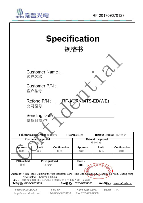
瑞丰RF-AURK14TS -ED(WE)产品规格书说明书
Date :日期:1-8th Floor, Building #1,10th Industrial Zone, Tian Liao Community, Gong Ming Area, Guang Ming栋一至八楼Web/网址:Features特征 PLCC-2 Package. 垂直型表贴封装 Extremely wide viewing angle. 发光角度大Suitable for all SMT assembly and solder process. 适用于所有的SMT 组装和焊接工艺 Available on tape and reel. 适用于载带及卷轴 Moisture sensitivity level: 3. 防潮等级:3 Package:3000pcs/reel. 包装:3000颗/卷 RoHS compliant. RoHS 认证 Description 描述 The Orange source color devices are made with AlGaInP on Substrate Light Emitting Diode橙光LED 由AlGaInP 四种元素芯片激发而成 Applications 应用 Optical indicator. 光学指示 Indoor display. 室内显示Landscape lighting,lamp belt. 景观照明,灯带等General suitable applications.其他适合的应用 RF-201709070127Package Dimension 封装尺寸 外形尺寸:2.0*1.4*1.3mmNOTES:备注1.All dimensions units are mm. (所有尺寸标注单位为毫米)2.All dimensions tolerances are 0.2mm unless otherwise noted. (除特别标注外,所有尺寸允许公差为±0.2毫米)Electrical / Optical Characteristics at Ts=25°C 电性与光学特性 Absolute Maximum Ratings at Ts=25°C 绝对最大值 Item 项目Symbol 符号test condition 测试条件Value unit 单位 Min. Max. Typ.Forward VoltageRank B1 VfIF=20mA1.8 1.92.1V RankB2 1.9 2.0 V Rank C12.0 2.1 V Rank C2 2.1 2.2 V Rank D1 2.2 2.3 V Rank D2 2.32.4 V Dominant wavelengthRank E00wld IF=20mA600 605 602.5 nm Rank F00 605 610 nm Luminous intensityRank H20 IVIF=20mA180 230 265 mcd Rank I10230 280 mcd Rank I20 280 350 mcd Rank J10350 430 mcd Reverse Current IR VR=5V --- 10 --- uAViewing Angle 2Θ1/2 IF=20mA --- --- 120 Deg Thermal resistanceRth(j-s)IF=20mA------290 ℃/WParameter (参数) Symbol (符号)Rating (值)Units (单位)Power Dissipation (功耗) Pd 48 mW Forward Current (正向电流) IF 20 mA Peak Forward Current (峰值电流) IFP 100 mA Reverse Voltage (反向电压) VR 5 V Electrostatic Discharge(HBM)(静电) ESD 2000 V Operating Temperature (操作温度) Topr -40 ~ +85 ℃ Storage Temperature (储存温度) Tstg -40 ~ +100℃ junction temperature (结温) Tj90℃Note: 1. 1/10 Duty cycle, 0.1ms pulse width. 脉宽0.1ms,周期1/10.2. The above forward voltage measurement allowance tolerance is 0.1V. 以上所示电压测量误差0.1V.3. The above wavelength measurement allowance tolerance is ±1nm. 以上所示波长测量误差±1nm.4. the above luminous flux measurement allowance tolerance ±10%. 上述光通量的测试允许公差为±10%.5. Care is to be taken that power dissipation does not exceed the absolute maximum rating of the product. 使用功率不能超过规定的最大值.6. All measurements were made under the standardized environment of us. 所有测试都是基于我们现有的标准测试平台.7.When the LEDs are in operation the maximum current should be decided after measuring the package temperature,junction temperature should not exceed the maximum rate.LED使用的最大电流需要根据散热条件确定,结温不能超过最大值Handling Precautions 使用注意事项1>.LED operating environment and sulfur element composition cannot be over 100PPM in the LED mating usage material. This is provided for informational purposes only and is not a warranty or endorsement.LED工作环境及与LED适配的材料中,硫元素及化合物成份不可超过100PPM,单一的溴元素含量要求小于900PPM,单一氯元素含量要求小于900PPM,溴元素与氯元素总含量必须小于1500PPM(检测含量为与LED直接接触面上元素含量)。
D-dimer测定试剂盒标准操作规程

D-二聚体标准操作规程(NycoCard D-dimer测定试剂盒)1. 检测目的:本试剂盒用于检测血浆中纤维蛋白的降解产物D-二聚体(D-dimer)的浓度。
可作为血栓性疾病诊治过程的重要辅助工具。
2.原理:基于免疫过滤试验原理,将血浆加入检测卡孔内,样品被吸入,D-dimer分子被吸附到包被D-dimer单克隆抗体的膜中,然后加入D-dimer单克隆抗体与胶体金偶联物溶液,膜中D-dimer将与抗体金偶联物发生结合反应,形成三明治嵌合体,过剩偶联物用洗涤液洗去。
样本中存在病理水平的D-dimer,检测膜显现微红色,颜色的深浅与样本中D-dimer的浓度成正比。
色泽强度可用比色卡进行对比评价,也可用读数仪(NycoCard® READER)进行读数。
3.试剂盒:NycoCard D-dimer测定试剂盒3.1试剂盒的组成:试剂盒的规格为48人份/盒3.11检测卡包装在铝箔袋内,每卡有6个检测孔,孔内的渗水膜包被D-dimer单克隆抗体。
卡已经过处理,允许使用记号笔在孔下的空白处对病人/标本的属性进行标记。
3.12偶联抗体反应液R1 1×3ml,黑盖棕色瓶,为D-dimer单克隆抗体与胶体金偶联物溶液。
3.13洗涤液R2 1×12ml,白色瓶盖,内容PH8.0的缓冲液,主要成分为小牛血清白蛋白及清洗剂。
3.14阳性质控品1×1ml,白色瓶盖,主要为纤维蛋白的降解产物与小牛血清白蛋白的缓冲液及稳定剂,参考值参见瓶签所示范围。
3.15判读比色卡1个,塑料比色卡,五个颜色逐深的孔分别代表0.3-8mg/L的5个水平D-dimer的浓度,用于判读检测结果。
3.16塑料袋2只,一只存放开启的未使用的检测卡,一只用于存放使用后的检测卡。
3.2试剂盒的储存条件:在2-8℃贮存,失效期见试剂盒上的标签。
避免储存温度超过25 ℃、光线直射和潮湿。
试剂盒室温下储存可达一周。
3.21检测卡检测卡在2-8℃保存在未开启的铝箔袋内或开启后放置在盒中的塑料袋内,可稳定至标签所示的效期。
试剂盒说明书-快速定量检测 D-Dimer-Triage D-Dimer Test

Triage D-Dimer Test 产品说明D-Dimer 的快速定量检测T r i a g e D -D i m e r T e s t 1符号术语表请参见 q u i d e l .c o m /g l o s s a r y仅供出口。
在美国没有销售。
计用途Q u i d e l T r i a g e D -D i m e r T e s t 是一种与 Q u i d e l T r i a g e检测仪合用的荧光免疫分析方法,用来定量检测 E D T A 抗凝全血和血浆样本中交联纤维蛋白降解产物中的 D -d i m e r 含量。
该检测方法用于辅助诊断和评估疑诊为弥漫性血管内凝血或血栓栓塞疾病(包括肺栓塞)的患者。
检测概要和说明在凝血过程中,凝血酶通过蛋白水解降解掉血纤肽 A 和血纤肽 B ,将纤维蛋白原转换为可溶 性纤维蛋白。
可溶性纤维蛋白自发聚合,而 D 区则在 X I I I a 因子的催化作用下形成共价交联。
交联纤维蛋白最终通过纤维蛋白溶解途径进行降解。
纤溶酶裂解交联纤维蛋白晶格中的共价键,并释放纤维蛋白降解产物 (F D P ),其中包括由两个 D 分子片段 (D -d i m e r ) 形成的一个分子量为 200 k D a 的交联分子。
曾有学者描述,在患有包括肺栓塞 (P E ) 和深静脉血栓 (D V T ) 的静脉血栓栓塞患者中,循环 D -d i m e r 有所升高(参见 G o l d h a b e r , S .Z . (1998) N e w E n g l. J . M e d . 339; 93-104)。
检测步骤的原理Q u i d e l T r i a g eD -D i m e r T e s t 是一种一次性荧光免疫分析测试装置,用于确定E D T A 抗凝全血或血浆标本中的 D -d i m e r 浓度。
检测步骤包括向测试卡的样品端口添加几滴 E D T A 抗凝全血或血浆样本。
RevcoTM RDE 系列、 FormaTM FDE 系列、 HERAfreezeTM HDE 系

超低温降温仪 Revco TM RDE 系列、Forma TM FDE 系列、HERAfreeze TM HDE 系列和 Thermo Scientific TM TDE 系列安装和操作329712H61 •修订版 F • 2022 年 3 月重要请阅读本说明手册。
不按照本手册中的说明操作可能会导致设备损坏、操作人员受伤和设备性能低下。
小心所有内部调整和维护均必须由合格的检修人员执行。
本手册中的材料仅供参考。
其中的内容和产品可能发生更改,恕不另行通知。
赛默飞世尔科技不提供任何关于本手册的声明或担保。
在任何情况下,Thermo 对因使用本手册或与使用本手册相关的直接或间接损坏不负任何责任。
© 2022 Thermo Fisher Scientific Inc. 保留所有权利。
目录型号 (1)安全注意事项 (2)开箱 (3)装箱单 (3)一般性建议 (4)温度监测 (4)一般用法 (4)初次装载 (4)电池舱门打开/关闭 (4)运行标准 (5)电气规格 (5)安装 (6)位置 (6)保护导体电流 (6)调平 (6)刮冰刀 (6)备份系统(可选) (7)超级绝缘机柜结构 (7)门操作 (7)压力均衡口 (7)安装远程警报连接器 (7)预期用途 (8)操作 (9)初始启动 (9)操作概述 (9)显示 (9)设置 (10)关机 (10)刮冰刀说明 (11)预期用途 (11)非预期用途 (11)注意事项和使用方法 (11)备份系统(可选) (12)CO2和 LN2注意事项 (12)安装 (12)启动 (13)操作 (13)温度记录仪(可选) (14)设置和操作 (14)更换记录纸 (14)校准调整 (14)维护 (15)清洁冷凝器 (15)清洁冷凝器过滤器 (15)垫圈维护 (15)为降温仪除霜 (15)电池维护 (15)维护计划 (16)故障排除指南 (17)错误代码 (20)保修 (21)保修(国际) (22)附录 A:警报摘要 (23)附录 B:Modbus ASCII 参数表 (25)WEEE 合规 (34)联系信息 (35)型号表 1. 适用的型号Forma - FDExxx86F*300/400/500/600A/D/VForma - FDExxx86F* - ULTS 300/400/500/600A/D/VThermo Scientific –TDExxx86F*300/400/500/600A/D/VThermo Scientific –TDExxx86F*- ULTS300/400/500/600A/D/VHERAfreeze – HDExxx86F*300/400/500/600A/D/VRevco - RDExxx86F*300/400/500/600A/D/V1|型号Thermo Fisher Scientific 超低温降温仪安全注意事项在本手册中,使用下列符号和惯例:下面列举了一些适用于本产品的重要安全防范措施:EMC(适用时)此设备的 EMC 注册仅限商业用途。
微蓝生物显微镜系列产品技术参数说明书
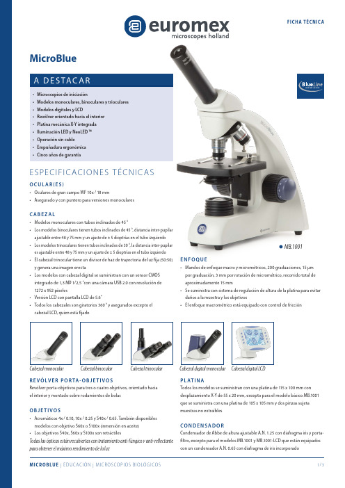
MB.1001E NF O Q U ESos modelos binoculares tienen tubos inclinados de 45 °, distancia inter-pupilar ajustable entre 48 y 75 mm y un ajuste de ± 5 dioptrías en el tubo izquierdo os modelos trinoculares tienen tubos inclinados de 30 °, la distancia inter-pupilar es ajustable entre 48 y 75 mm y un ajuste de ± 5 dioptrías en el tubo izquierdo l cabezal trinocular tiene un divisor de haz de trayectoria de luz fija (50:50)MB.1051-LCDMB.1155 MB.1153MB.1152 MB.1051I LU M I N AC I ÓN• T odas las versiones monoculares se suministran con una iluminación LED 1W de intensidad ajustable• L as versiones binoculares y trinoculares se suministran con un sistema de iluminación NeoLED ™ 1W de intensidad ajustable• T odos los modelos tienen baterías internas recargables con un cargador de batería externo de 100-240 V / adaptador de redCO N T E N I D O I N C LU I D O• S e suministra con cargador de adaptador de red, filtro blanco, cubierta anti-polvo, manual de usuario y aceite de inmersión de 5 ml para modelos con objetivo S100x. Software incluido para modelos digitales y para los modelos LCD• Todo empacado en una caja de poliestirenoMODELOS DIGI TALESC ÁM A R A• C ámara integrada CMOS USB-2 de 1.3 MP• R esolución máxima de 1272 x 952, profundidad de color de 24 bits, hasta 30 fotogramas por segundo• S e entrega con el software ImageFocus 4, cable USB-2 y un patrón de calibración de 1 mm / 100 partes • La garantía para la cámara es de dos añosS O F T WA R E• E l software ImageFocus 4 de captura y análisis permite guardar imágenes en formatos .jpg, .tif o .bmp, así como videos en formato .avi• L as imágenes se pueden anotar y las mediciones se pueden realizar en imágenes en vivo o capturadas• C ompatible con Windows 7, 8 y 10, configuraciones de 32 y 64 bits • L a versión Mac OS Light también está disponible para capturar imágenes • L as actualizaciones se pueden descargar en nuestro sitio web PA N TA L L A LC DTodos los microscopios MicroBlue LCD vienen con una pantalla LCD de 5.6”• Resolución de la pantalla 640 x 480• Las imágenes y los videos se guardan directamente en la tarjeta SD • R esolución de imagen 2048 x 1536, 1600 x 1200, 1280 x 960, 640 x 480 en formato .JPEG• Resolución video 640 x 480 en formato .AVI• Suministrado con el programa Imagebasic et cable USB.2• Garantía de 2 años para la cámaraP R O G R A M A I M AG E B A S I C• E l programa de captura permite guardar imágenes en formato.jpg y videos en formato .avi• Compatible con Windows 7, 8 et 10, en configuraciones de 32 y 64 bits • L as actualizaciones se pueden descargar desde nuestra página web EuromexMicroscopenbv•Papenkamp20•6836BDArnhem•TheNetherlands•T+31(0)263232211•F+31(0)263232833•****************•ACCESORIOS Y REPUES TOSMB.6010 Ocular de gran campo WF10x/18 mmMB.6010-P Ocular de gran campo WF10x/18 mm con puntero MB.6010-M Ocular de gran campo WF10x/18 mm micrométrico MB.6015 Ocular de gran campo WF15x/11 mm MB.6020 Ocular de gran campo WF20x/9 mm MB.6099 Pareja de protectores de gomaMB.7004 Objetivo acromático 4x/0.10, para-focal 35 mm MB.7010 Objetivo acromático 10x/0.25, para-focal 35 mm MB.7020 Objetivo acromático 20x/0.40, para-focal 35 mm MB.7040 Objetivo acromático S40x/0.65, para-focal 35 mm MB.7060 Objetivo acromático S100x/1.25, para-focal 35 mm MB.9710 Filtro esmeriladoMB.9900 Maleta de transporte de aluminioAE.9918 Bolsa de microscopio de nylon, dimensiones 26 x 18 x 400 mm MB.9975 Adaptador de red / cargador externo 100-240 Vca / 5 Vcc (50/60 Hz)MB.9981 Recambio 1W LED MB.9991 Recambio 1W NeoLEDM O D E LO SMono Bino TrinoObjetivos máximos Objetivos 4/10/S40xObjetivo S60xObjetivo S100x Platina mecánica X-YLED NeoLED BateríasMB.1001 •3•••MB.1051•4••••MB.1651•4•••••MB.1151•4•••••MB.1052•4••••MB.1652•4•••••MB.1152•4•••••MB.1053•4••••MB.1653•4•••••MB.1153•4•••••M O D E LO SDigital LCD Digital mono Objetivos máximos Objetivos 4/10/S40x Objetivo S60x Objetivo S100x Platina mecánica X-YLED NeoLED BateríasMB.1001-LCD*•3•••MB.1051-LCD*•4••••MB.1055•4••••MB.1655•4•••••MB.1155•4•••••* modelos con pantalla LCDPB.5155 P orta-objetos de 76x26 mm., cantos pulidos(caja de 50 unidades)PB.5157-W P orta-objetos de 76x26 mm., cantos pulidos. Banda blanca(caja de 50 unidades)PB.5157-B P orta-objetos de 76x26 mm., cantos pulidos. Banda azul(caja de 50 unidades)PB.5160 P orta-objetos de 76x26 mm., cantos pulidos. Con cavidad(caja de 10 unidades)PB.5165 C ubre-objetos de 18x18mm., 0.13-0.17 mm.(caja de 100 unidades)PB.5168 C ubre-objetos de 22x22mm., 0.13-0.17 mm.(caja de 100 unidades)PB.5245 Papel de limpieza de lentes (paquete de 100 hojas)PB.5255 Aceite de inmersión, n=1.482 (25 ml.)PB.5274 Alcohol isopropilico 99% (200 ml.)PB.5275 K it de limpieza compuesto por líquido de limpieza de lentes,gamuza, papel de limpieza de lentes, cepillo, pera de aire y bastoncillos de algodón.。
DME样本含量讲稿2k1028
46
队列研究所需样本含量
RR 2.0 对照组中事件的发生率
1/10000 1/5000 1/1000 1/500
235500
177732
23518
11741
2.5 3.0
5.0 7.5 10.0
122108 78496
29432 15788 10658
64043 39240
14711 7890 5324
39
计数资料样本含量的估算 (查表法)
设青霉素治疗慢性气管炎近期控制率仅为20%( P1),现拟用某中药治疗,要求该中药近期控制率 须达40%(P 2 )才能有推广意义,设α =0.05,
检验效能为90%,问需多少病例才能得到两组比
较具有显著性差异的结论?
δ =P2-P1=40-20=20
=0.05, Power=90%,双侧检验
9
诊断标准
Wetterling T 等连续收集神经精神科 病人167名(年龄:72.0±9.9岁)。 血管性痴呆的诊断 DSM-IV ICD-10 45/167 21/167 5/167 ADDTC NINCDS-AIREN 23/167 12/167
DSM-IV: 精神疾病诊断与统计手册,美国精神病协会,94, ICD-10: 国际疾病分类与疾病,10ed, WHO, 92 ADDTC: 美国加州AD诊断与治疗中心 NINCDS-AIREN: 美国神经系统疾病与卒中研究所-瑞士神经科学研究国际协会,93
15
某中药复方治疗急性腹泻安全性及有效性评价
诊断标准:《内科疾病诊断标准》(贝 政平主编,科学出版社2001年) 纳入标准:
符合急性腹泻诊断标准及中医辩证标准 排除标准: 病情属轻度和中度 •急性腹泻见脓血便 病程72小时内 年龄18-65岁 •发热38.6摄氏度以上 签署知情同意书 •妊娠或哺乳期妇女
六西格玛M阶段模板
8
OK
OK
OK
OK
OK
9
OK
OK
OK
OK
OK
10
OK
OK
OK
OK
NG
11
NG
NG
NG
NG
NG
12
NG
NG
NG
NG
NG
13
OK
OK
OK
OK
OK
14
NG
NG
NG
NG
NG
15
NG
NG
NG
NG
NG
16
NG
NG
NG
NG
NG
17
OK
OK
OK
OK
OK
18
NG
NG
NG
OK
NG
19
OK
OK
OK
OK
OK
20
NG
NG
NG
UCL=0.3222
P=0.1648
LCL=0.007398
5
10
15
20
25
Sample Number
Expected Defectives
Binomial Plot
12 11 10
9 8 7 6 5 4 3
3 4 5 6 7 8 9 10 11 12
Observed Defectives
Cumulative %Defective
板材来料抗冲击强度不合格 9
3
拉丝时间不够
9
3
吸附模具R角太小
3
9
内胆厚度不达标
D-M-A-I-C
GAGE R&R验证
Extech Instruments 400模型数字多功能表说明书
Common Features:•Large backlit LCD display with easy-to-read 1" digits •Type K thermometer built-in for temperature measurements •Low current capability:measure down to 0.1μA •Input fuse protection and mis-connection warnings •Complete with CAT III test leads, multi-position tilt standand velcro strap for hanging,protective holster with testlead holder, bead wiretemperature probe (-4 to 482°F/-20 to 250°C),and 9V batteryRugged design with built-in IR ThermometerExtech 400 Series Multimeters are available with or without the built-in InfraRed thermometer, select auto or manual ranging, True RMS or averaging, and choosethe meter you want at a price you can afford.Extech 400 Series MultiMetersOrdering Information EX410..............Manual Ranging MultiMeter EX410-NIST ......EX410 MultiMeter w/ NIST Certificate EX411..............True RMS Manual Ranging MultiMeter EX411-NIST ......EX411 MultiMeter w/ NIST Certificate EX420..............Autoranging MultiMeter EX420-NIST ......EX420 MultiMeter w/ NIST Certificate EX430..............True RMS Autoranging MultiMeter EX430-NIST ......EX430 MultiMeter w/ NIST Certificate EX450..............Autoranging MultiMeter + IR Thermometer EX450-NISTL ....EX450 MultiMeter w/ NIST Certificate EX470..............True RMS Autoranging MultiMeter + IR Thermometer EX470-NISTL ....EX470 MultiMeter w/ NIST CertificateAccessoriesCA500..............Case with shoulder strap and side pockets TP873..............Replacement Bead wire Temperature Probe HG500..............Magnetic Hanging StrapModel EX450•Built-in IR Thermometer•AutorangingModel EX470•Built-in IR Thermometer•True RMS•Autoranging•Capacitance•Frequency•Relative functionModel EX410/EX411•True RMS (EX411)•Manual Ranging Model EX420/EX430•True RMS (EX430)•Autoranging •Capacitance •Frequency。
D-二聚体(D-Dimer)测定试剂盒(胶体金免疫层析法)产品技术要求贝尔
D-二聚体(D-Dimer)测定试剂盒(胶体金免疫层析法)产品技术要求贝尔D-二聚体(D-Dimer)测定试剂盒(胶体金免疫层析法)适用范围:用于体外定量测定人血清或血浆中的D-二聚体(D-Dimer)含量。
1.1 包装规格20人份/盒1.2主要组成成分本试剂盒由D-Dimer检测卡、干燥剂和滴管组成。
D-Dimer检测卡由试纸条外壳与试纸条构成,试纸条由样品垫、胶体金垫(喷有由胶体金标记的D-Dimer单克隆抗体)、层析膜(T线包被有D-Dimer 单克隆抗体,C线包被有羊抗鼠IgG抗体)、吸水纸、衬垫构成。
检测卡为20人份/盒,干燥剂为1个/袋、滴管为20个/盒。
2.1 物理性状2.1.1 外观试剂盒各组分齐全、完整;包装袋应密封性好无破损;标签清晰;材料附着牢固,条宽应适应于卡壳且装配紧密。
2.1.2 膜条宽度膜条宽度应不低于4.0mm。
2.1.3 液体移行速度液体移行速度应不低于10mm/min。
2.2 空白检出限应小于0.1mg/L。
2.3 分析特异性分别用浓度为1000ng/mL肌酸激酶同工酶MB(CK-MB)、1000ng/ml肌红蛋白(Myo)、1000ng/ml心肌肌钙蛋白T(cTnT)、1000ng/ml心肌肌钙蛋白I(cTnI)、5000ng/ml C反应蛋白(CRP)分析特异性参考品进行测定,结果应小于0.1mg/L。
2.4 重复性用0.5mg/L D-二聚体(D-Dimer)参考品和2.0mg/L D-二聚体(D-Dimer)参考品重复检测10次,其变异系数(CV)应不大于15%。
2.5 准确度将D-Dimer含量为5.0mg/L人血清参考品加入到D-Dimer含量为0.1mg/L的正常人血清参考品中,参考品按照体积比1:9混合,对混合后样本进行检测,回收率应在85%~115%范围内。
2.6 线性D-二聚体(D-Dimer)检测线性范围为[0.1,5.0]mg/L,试剂盒相关系数r应≥0.99。
- 1、下载文档前请自行甄别文档内容的完整性,平台不提供额外的编辑、内容补充、找答案等附加服务。
- 2、"仅部分预览"的文档,不可在线预览部分如存在完整性等问题,可反馈申请退款(可完整预览的文档不适用该条件!)。
- 3、如文档侵犯您的权益,请联系客服反馈,我们会尽快为您处理(人工客服工作时间:9:00-18:30)。
1/16Proportional pressure reducing valve, pilot operatedType DRE(M) and DRE(M)ESizes 10 and 25 1)Component series 6XMaximum operating pressure 315 bar Maximum flow 300 l/minRE 29276/03.11Replaces: 01.10Table of contentsContents PageFeatures 1Ordering code 2Symbols 3Function, section 4 and 5Technical data6 and 7Electrical connection, mating connectors 8Control electronics 9Characteristic curves 10 and 11Unit dimensions12 to 14Features– Valve for reducing an operating pressure – Operation by means of proportional solenoids– Proportional solenoid with rotatable and detachable coil – For subplate mounting:Porting pattern according to ISO 5781,Subplates according to data sheet RE 45062 (separate order), see page 11– Third path A to Y (Ø 7.5 mm)– Minimum setting pressure 2 bar with command value zero – Linearized command value-pressure characteristic curve – Good transient response– Optional check valve between A and B – Maximum pressure limitation optional– Type DRE(M)E with integrated electronics (OBE):• Little manufacturing tolerance of the command value- pressure characteristic curveInformation on available spare parts: /spc1) Size 32 see data sheet RE 29278Ordering codewithout maximumpressure limitation = no codewith maximumpressure limitation 1)= MFor externalcontrol electronics = no codewith integrated electronics (OBE) = ESize 10 = 10Size 25 = 20Component series 60 to 69 = 6X(60 to 69: Unchanged installation andconnection dimensions)Pressure rating50 bar = 50100 bar = 100200 bar = 200315 bar = 315Pilot oil return always external = Y separately and at zero pressure to the tankwith check valve between A and B = no code without check valve= MFurther details inthe plain textSeal materialM = NBR sealsV = FKM sealsInterface electronicsA1 = Command value 0 to 10 VF1 = Command value 4 to 20 mAno code = with DREElectrical connectionfor DRE(M):K4 =without mating connector,with connector according toDIN EN 175301-803Mating connector - separate ordersee page 8for DRE(M)E:K31 = without mating connector,with connector according toDIN EN 175201-804Mating connector - separate ordersee page 8 no code = 1600 mA design- 8 =800 mA design 2)Supply voltage of the control electronics G24 = Direct voltage 24 VDRE 6X Y G24*Accessories (not included in scope of delivery)– External control for type DRE (only standard version G24(1.6 A solenoid)):• Analog amplifier VT-MSPA1-11-1X/in modular design according to data sheet RE 30223 • Digital amplifier VT-VSPD-2in Eurocard format according to data sheet RE 30523 • Analog amplifier VT-VSPA1-11-1X/in Eurocard format according to data sheet RE 30100 • Proportional plug-in amplifier VT-SSPA1-1-1X plug-in amplifier according to data sheet RE 30116 connection M12 - 4-pole– Mating connectors (details, see page 8)• For DRE(M): According to DIN EN 175301-803, Material no. R901017011• For DRE(M)E: According to DIN EN 175201-804, Material no. R900021267 or R9002238901) In case of an error (e.g. in case of contamination or overcurrent), the maximum pressure limitation prevents an inadmissibly high overpressure at the valve.2) Replacement series 5X (Attention! External am-plifiers only suitable for G24 = 1.6 A solenoid), see accessories.SymbolsDRE -6X/...YM …DREM -6X/...YM …DRE -6X/...Y …DREM -6X/...Y …DREE -6X/...YM …DREME -6X/...YM …DREE -6X/...Y …DREME -6X/...Y …Function, sectionType DREM…-6X/…YG24K4... (with check valve)Valves of type DRE(M) are pilot controlled pressure reducing valves. They are used for reducing an operating pressure.These valves basically comprise of a pilot control valve (1) with proportional solenoid (2), main valve (3) with main spool insert (4), as well as an optional check valve (5).Type DRE...The pressure in channel A is set in a command value-depen-dent form via the proportional solenoid (2).In rest position - no pressure in channel B -, the spring (17) holds the main spool (4) in its initial position. The connection from channel B to A is closed. A start-up jump is thus suppressed.Via the bore (6), the pressure in channel A acts on the sur-face (7) of the main spool. The pilot oil is taken from channel B and flows via the bore (8) to the constant flow controller (9) keeping the pilot flow constant, independent of the pressure drop between channel A and B. From the constant flow con-troller (9), the pilot flow flows into the spring chamber (10), through the bores (11) and (12) via the valve seat (13) into the Y channel (14, 15, 16) and from there to the return.The pressure required in channel A is preset at the related am-plifier. The proportional solenoid moves the valve poppet (20) in the direction of the valve seat (13) and limits the pressure in the spring chamber (10) to the set value. If the pressure in channel A is lower than the specified command value, the higher pressure in the spring chamber (10) pushes the main spool to the right. The connection from B to A is opened.If the set pressure in A is achieved, the forces at the main spool are balanced - the main spool is in control position.Pressure in channel A • Spool face (7) =Pressure in the spring chamber (10) • Spool face – Spring force (17)If in a standing hydraulic fluid column (e.g. cylinder piston to stop), the pressure in A is to be reduced, a lower command value is (e.g.) specified at the control electronics and thus, a lower pressure is pre-selected that is immediately applied to the spring chamber (10). The higher pressure in A at the face (7) of the main spool pushes the main spool against the plug screw (18) to stop. The connection A to B is blocked and A to Y is open. The force of spring (17) now acts against the hydraulic force at the face (7) of the main spool. In this main spool position, the hydraulic fluid can flow from channel A via the control edge (19) to Y into the return.If the pressure in A has been reduced to the pressure in the spring chamber (10) plus ∆p from spring (17), the main spool at the control edge A to Y closes the large control bores in the socket.The remaining differential pressure of approx. 10 bar to the new command value pressure in A is only discharged via the fine control bore (21). This results in a good transient re-sponse without pressure undershoots.For the free return flow from channel A to B, a check valve (5) can optionally be installed. A part of this flow from channel A simultaneously flows via the open control edge (19) of the main spool from A to Y into the return.Type DREM...For hydraulic protection against an inadmissibly high electric control current at the proportional solenoid, which imperatively results in increased pressures in port A, you can optionally install a spring-loaded pressure relief valve as maximum pressure limitation (22). The maximum pressure limitation is pre-set referred to the relevant pres-sure rating (table page 6).23Type DRE(M) – with integrated electronics (OBE)With regard to function and structure, these types correspond to type DRE. On the proportional solenoid, there is moreover a housing (23) with the control electronics.Supply and command value voltage are applied at the con-nector (24).In the factory, the command value pressure characteristic curve is adjusted with little manufacturing tolerance.For more information on the control electronics see page 8.Function, sectionType DRE(M)E…-6X/…YG24K31...Technical Data (For applications outside these parameters, please consult us!)generalSize Size1025 Weight– DRE and DREM kg 4.7 6.0– DREE and DREME kg 4.8 6.1 Installation position AnyStorage temperature range°C–20 to +80Ambient temperature range– DRE(M)°C–20 to +70– DRE(M)E°C–20 to +50hydraulic (measured with HLP 46, ϑoil = 40 °C ± 5 °C)Size Size1025 Max. operating pressure– Port A and B bar315– Port Y Separately and to the tank at zero pressure(internal pipe Ø ≥ 5 mm; pipe length < 2500 mm) Max. setting pressure– Pressure rating 50 bar bar50in channel A– Pressure rating 100 bar bar100– Pressure rating 200 bar bar200– Pressure rating 315 bar bar315Min. setting pressure in channel A with command value zero bar2Maximum pressure limitationSet in the factory:(fixedly set)– Pressure rating 50 bar bar To 70 bar– Pressure rating 100 bar bar To 130 bar– Pressure rating 200 bar bar To 230 bar– Pressure rating 315 bar bar To 350 barMax. flow of the main valve l/min200300Pilot flow l/min0.8Hydraulic fluid On mineral oil basis and related hydrocarbons(HL, HLP, HLPD, HLPP) according to DIN 51524 1)Flame-resistant – water-free (HFDU(G), HFDU(E),HFDR) according to ISO12922 2), 4)Flame-resistant – containing water (HFC: FuchsHydrotherm 46M, Petrofer Ultra Safe 620) accordingto ISO12922 3), 4)Hydraulic fluid temperature range°C–20 to +80Viscosity range mm2/s15 to 380Class 20/18/15 5)Max. admissible degree of contamination of the hydraulic fluidCleanliness class according to ISO 4406 (c)Hysteresis%±3.5 of the max. setting pressure 6) Repeatability%< ±2 of the max. setting pressure 6)Linearity%±2 of the max. setting pressure 6) Manufacturing tolerance of the– DRE(M)%±3.5 of the max. setting pressure 6)command value pressure characteristic – DRE(M)E%±1.5 of the max. setting pressure 6)curve, related to the hysteresis characteristic curve, pressure increasingStep response T u + T g10 → 90 %ms∼130Measured with standing hydraulic fluid column,90 → 10 %ms∼160 1 liter at port AStep response T u + T g10 → 90 %ms∼150Measured with standing hydraulic fluid column,90 → 10 %ms∼150 5 liters at port AFoot notes see next pageTechnical Data (For applications outside these parameters, please consult us!)electric"G24""G24-8"Minimum solenoid current mA ≤ 100≤ 100Maximum solenoid current mA 1600 ± 10 %800 ± 5 %Solenoid coil resistance Cold value at 20 °C Ω 5.520.6Max. hot valueΩ833Duty cycle%100100Caution!With an ambient temperature of 70 °C and a duty cycle of 100 % with max. current, the coil of the 800 mA solenoidreaches temperatures of up to 170 °C. In case of contact with the coil, this may lead to burns.1) Suitable with NBR and FKM seals 2) Suitable only with FKM seals 3) Suitable only with NBR seals4) When using flame-resistant hydraulic fluids HFC, thefollowing limitations are to be observed:– Max. operating pressure 210 bar – Max. hydraulic fluid temperature 60 °C– Expected service life 30...100 % as compared to HLP5) The cleanliness classes specified for the components mustbe adhered to in hydraulic systems. Effective filtration pre-vents faults and at the same time increases the service life of the components.For the selection of the filters see /filter6) Does not apply to types "G24 - 8"PE12A F ED C BA F ED CB Electrical connection (dimensions in mm)Mating connectors according to DIN EN 175201-804, solder contacts for line cross-section 0.5 to 1.5 mm 2Mating connector (black) according to DIN EN 175301-803 Material no. R901017011 (separate order)Connection at mating connectorTo the amplifierConnection at connectorMetal version,material no. R900223890 (separate order)DRE(M)DRE(M)EPlastic version,material no. R900021267, (separate order)2224262830204060801000,75 mm 21 mm 2Integrated electronics (OBE) with type DRE(M)EBlock diagramCommand value actual value command valueActual valueGND24 VDC Supply FunctionThe electronics are supplied with voltage via ports A and B. The command value is applied to the differential amplifier ports D and E.Via the characteristic curve generator, the command value solenoid current characteristic curve is adjusted to the valve so that non-linearities in the hydraulic system are compensat-ed and thus, a linear command value pressure characteristic curve is created.The current controller controls the solenoid current indepen-dent of the solenoid coil resistance.The power section of the electronics for controlling the pro-portional solenoid is a chopper amplifier with a cycle fre-quence of approx. 180 Hz to 400 Hz. The output signal is pulse-width modulated (PWM).For checking the solenoid current, a voltage can be measured between pin F(+) and pin C(–) that is proportional to the sole-noid current. 1 mV corresponds to 1 mA solenoid current.Electrical connectionM i n . s u p p l y v o l t a g e i n V →Length in m →Connection cable for DRE(M)E– Recommendation 6-wire, 0.75 or 1 mm 2 plus protective earthing conductor and screening– Only connect the screening to PE on the supply side– Max. admissible length 100 mThe minimum supply voltage at the mains adapter depends on the length of the supply line (see diagram).2040608010010020204060808060401002001601208040501001502003003152500501001502003003152502502001501005051015203002525020015010050510152030025Pressure in channel A dependent on the flow q v (characteristic curve with constant ∆p)Size 10Size 25Flow in l/min →P r e s s u r e i n c h a n n e l A i n b a r →Flow in l/min →P r e s s u r e i n c h a n n e l A i n b a r →Pressure differential via the check valve from A to BFlow in l/min →P r e s s u r e d i f f e r e n t i a l i n b a r →Flow in l/min →Pressure differential from B to AP r e s s u r e d i f f e r e n t i a l i n b a r →Size 25Size 10Size 25Size 10Characteristic curves (measured with HLP46, ϑoil = 40 °C ± 5 °C)Pressure in port A depending on the command value (flow = 0.8 l/min)P r e s s u r e i n p o r t A i n % →DRE(M)E Command value in % →P r e s s u r e i n p o r t A i n % →1) With valve DRE(M), the manufacturing tolerance at the ex-ternal amplifier (type and data sheet see page 2) can be changed using the command value attenuator potentiom-eter "Gw ". With the digital amplifier, the setting is made us-ing the "Limit" parameter.In this connection, the control current according to the tech-nical data must not be exceeded.In order to be able to adjust several valves to the same characteristic curve, the pressure must - with a command value of 100 % - at no valve not exceed the maximum set-ting pressure of the relevant pressure rating.100806040201020304050100806040202040608010010080604020408012016020010080604020601201802403001008060402040801201602001008060402020406080100Serie 5XSerie 6XComparison series 5X-6X / pressure rating 100 bar (with amplifier VT-VSPA1-1-1X with 800 mA coil)Command value in % →P r e s s u r e i n c h a n n e l A i n b a r →1008060402060120180240300Serie 5XSerie 6XCommand value in % →P r e s s u r e i n c h a n n e l A i n b a r →Comparison series 5X-6X / pressure rating 315 bar (with amplifier VT-VSPA1-1-1X with 800 mA coil)Pressure in channel A depending on the command valuePressure rating 50 bar Pressure rating 200 barPressure rating 100 barPressure rating 315 barCommand value in % →P r e s s u r e i n c h a n n e l A i n b a r →Command value in % →P r e s s u r e i n c h a n n e l A i n b a r →Command value in % →P r e s s u r e i n c h a n n e l A i n b a r →Command value in % →P r e s s u r e i n c h a n n e l A i n b a r →Characteristic curves (measured with HLP46, ϑoil = 40 °C ± 5 °C and amplifier VT VSPA1-11-1X, 1600 mA coil...)Pressure rating 200 bar (with VT-SSPA1)Command value in % →P r e s s u r e i n c h a n n e l A i n b a r →Unit dimensions type DRE(M) (dimensions in mm)Size B1B2B3B4ØD1ØD2H11H1H2H3H4 108566.758.87.91521.81711235836 2510279.473 6.42534.81851376444 Size L1L2L3L4L5L6L7L8L9L10T1 1042.935.831.821.57.221.5511644.559.5 2.0 2560.349.244.520.611.139.712.211627.342 2.9 Size B5B6L11L1210848.65619.0525978.8788.85Unit dimensions type DRE(M)E (dimensions in mm)valve mounting face Size B1B2B3B4ØD1ØD2H11H1H2H3H4 108566.758.87.91521.81921235836 2510279.473 6.42534.82061376444 Size L1L2L3L4L5L6L7L8L9L10T1 1042.935.831.821.57.221.5511644.559.5 2.0 2560.349.244.520.611.139.712.211627.342 2.9Unit dimensions (continued)1Upon delivery, this port (G1/4) is closed. After removal of the blanking plug, an external and separate pilot oilreturn at zero pressure to the tank is, however, also pos-sible here.2Space required for removing the mating connector3Name plate4Blind counterbore5Check valve, optional6 Locating pin7Identical seal rings for ports A and BIdentical seal rings for port Y and blind counterbore(item 4)8Pilot oil return always external and separately at zeropressure to the tank, or optionally at item 19Mating connector according to DIN EN 175301-80310Integrated electronics (OBE), type DRE(M)E with con-nector "K31"11Mating connector according to DIN EN 175201-80412Processed installation surface, porting pattern according to ISO 5781-06-07-0-00 (size 10)ISO 5781-08-10-0-00 (size 25)13Cable fastening14Maximum pressure limitation with version DREM and DREME Subplates according to data sheet RE 45062 and valve mounting screws must be ordered separately. Subplates:Size 10: G 460/01 (G 3/8)G 461/01 (G 1/2)Size 25: G 412/01 (G 3/4)G 413/01 (G 1)Valve mounting screws:4 hexagon socket head cap screwsISO 4762-M10x45-10.9-flZn-240h-L(friction coefficient µtotal = 0.09 to 0.14,Tightening torque M A = 59 Nm ± 10 %or4 hexagon socket head cap screws ISO 4762-M10x45-10.9 (friction coefficient µtotal = 0.12 to 0.17)Tightening torque M A = 75 Nm ± 10 %Bosch Rexroth AG HydraulicsZum Eisengießer 197816 Lohr am Main, Germany Phone +49 (0) 93 52 / 18-0 Fax +49 (0) 93 52 / 18-23 58 documentation@boschrexroth.de www.boschrexroth.de © This document, as well as the data, specifications and other informa-tion set forth in it, are the exclusive property of Bosch Rexroth AG. It may not be reproduced or given to third parties without its consent. The data specified above only serve to describe the product. No state-ments concerning a certain condition or suitability for a certain applica-tion can be derived from our information. The information given does not release the user from the obligation of own judgment and verification. It must be remembered that our products are subject to a natural process of wear and aging.NotesBosch Rexroth AG HydraulicsZum Eisengießer 197816 Lohr am Main, Germany Phone +49 (0) 93 52 / 18-0 Fax +49 (0) 93 52 / 18-23 58 documentation@boschrexroth.de www.boschrexroth.de © This document, as well as the data, specifications and other informa-tion set forth in it, are the exclusive property of Bosch Rexroth AG. It may not be reproduced or given to third parties without its consent. The data specified above only serve to describe the product. No state-ments concerning a certain condition or suitability for a certain applica-tion can be derived from our information. The information given does not release the user from the obligation of own judgment and verification. It must be remembered that our products are subject to a natural process of wear and aging.Notes。