模具数控加工计算机辅助刀具选择研究外文文献翻译、中英文翻译、外文翻译
数控技术和装备中英文对照外文翻译文献

中英文对照翻译(文档含英文原文和中文翻译)Numerical control technology and equipping development trend and countermeasureEquip the engineering level, level of determining the whole national economy of the modernized degree and modernized degree of industry, numerical control technology is it develop new developing new high-tech industry and most advanced industry to equip (such as information technology and his industry, biotechnology and his industry, aviation, spaceflight, etc. national defense industry) last technology and getting more basic most equipment. Marx has ever said "the differences of different economic times, do not lie in what is produced, and lie in how to produce, produce with some means of labor ". Manufacturing technology and equipping the most basic means of production that are that the mankind produced the activity, and numerical control technology is nowadays advanced manufacturing technology and equips the most central technology. Nowadays the manufacturing industry all around the world adopts numerical control technology extensively, in order to improve manufacturing capacity and level, improve the adaptive capacity and competitive power to the changeable market of the trends. In addition every industrially developed country in the world also classifies the technology and numerical control equipment of numerical control as the strategic materials of the country, not merely take the greatmeasure to develop one's own numerical control technology and industry, and implement blockading and restrictive policy to our country in view of " high-grade, precision and advanced key technology of numerical control " and equipping. In a word, develop the advanced manufacturing technology taking numerical control technology as the core and already become every world developed country and accelerate economic development in a more cost-effective manner, important way to improve the overall national strength and national position.Numerical control technology is the technology controlled to mechanical movement and working course with digital information, integrated products of electromechanics that the numerical control equipment is the new technology represented by numerical control technology forms to the manufacture industry of the tradition and infiltration of the new developing manufacturing industry, namely the so-called digitization is equipped, its technological range covers a lot of fields: (1)Mechanical manufacturing technology; (2)Information processing, processing, transmission technology; (3)Automatic control technology; (4)Servo drive technology;(5)Technology of the sensor; (6)Software engineering ,etc..1.Development trend of a numerical control technologyThe application of numerical control technology has not only brought the revolutionary change to manufacturing industry of the tradition, make the manufacturing industry become the industrialized symbol , and with the constant development of numerical control technology and enlargement of the application, the development of some important trades (IT , automobile , light industry , medical aret·Ostmen ,etc. ) to the national economy and the people's livelihood of his plays a more and more important role, because the digitization that these trades needed to equip has already been the main trend of modern development. Numerical control technology in the world at present and equipping the development trend to see, there is the following several respect [1- ] in its main research focus.1.1 A high-speed, high finish machining technology and new trend equippedThe efficiency, quality are nonmanufacturing technology. High-speed, high finish machining technology can raise the efficiency greatly , improve the quality and grade of the products, shorten production cycle and improve the market competitive power. Japan carries the technological research association first to classify it as one of the 5 great modern manufacturing technologies for this, learn (CIRP) to confirm it as the Centre in the 21st century and study one of the directions in international production engineering.In the field of car industry, produce one second when beat such as production of 300,000 / vehicle per year, and many variety process it is car that equip key problem that must be solved one of; In the fields of aviation and aerospace industry, spare parts of its processing are mostly the thin wall and thin muscle, rigidity is very bad, the material is Luminal or Luminal alloy, only in a situation that cut the speed and cut strength very small high, could process these muscles, walls. Adopt large-scale whole Luminal alloy method that blank " pay empty " make the wing recently, such large-scale parts as the fuselage ,etc. come to substitute a lot of parts to assemble through numerous rivet , screw and other connection way, make the intensity , rigidityand dependability of the component improved. All these, to processing and equipping the demand which has proposed high-speed, high precise and high flexibility. According to EMO2001 exhibition situation, high-speed machining center is it give speed can reach 80m/min is even high , air transport competent speed can up to 100m/min to be about to enter. A lot of automobile factories in the world at present, including Shanghai General Motors Corporation of our country, have already adopted and substituted and made the lathe up with the production line part that the high-speed machining center makes up. Hyper Mach lathe of U.S.A. CINCINNATI Company enters to nearly biggest 60m/min of speed, it is 100m/min to be fast, the acceleration reaches 2g, the rotational speed of the main shaft has already reached 60 000r/min. Processing a thin wall of plane parts, spend 30min only, and same part general at a high speed milling machine process and take 3h, the ordinary milling machine is being processed to need 8h; The speed and acceleration of main shaft of dual main shaft lathes of Germany DMG Company are up to 120000r/mm and 1g.In machining accuracy, the past 10 years, ordinary progression accuse of machining accuracy of lathe bring 5μm up to from 10μm already, accurate grades of machining center from 3~5μm, rise to 1~1.5μm, and ultraprecision machining accuracy is it enter nanometer grade to begin already (0.01μm).In dependability, MTBF value of the foreign numerical control device has already reached above 6 000h, MTBF value of the servo system reaches above 30000h, demonstrate very high dependability .In order to realize high-speed, high finish machining, if the part of function related to it is electric main shaft, straight line electrical machinery get fast development, the application is expanded further .1.2 Link and process and compound to process the fast development of the lathe in 5 axesAdopt 5 axles to link the processing of the three-dimensional curved surface part, can cut with the best geometry form of the cutter , not only highly polished, but also efficiency improves by a large margin . It is generally acknowledged, the efficiency of an 5 axle gear beds can equal 2 3 axle gear beds, is it wait for to use the cubic nitrogen boron the milling cutter of ultra hard material is milled and pared at a high speed while quenching the hard steel part, 5 axles link and process 3 constant axles to link and process and give play to higher benefit. Because such reasons as complicated that 5 axles link the numerical control system , host computer structure that but go over, it is several times higher that its price links the numerical control lathe than 3 axles , in addition the technological degree of difficulty of programming is relatively great, have restricted the development of 5 axle gear beds.At present because of electric appearance of main shaft, is it realize 5 axle complex main shaft hair structure processed to link greatly simplify to make, it makes degree of difficulty and reducing by a large margin of the cost, the price disparity of the numerical control system shrinks. So promoted 5 axle gear beds of head of complex main shaft and compound to process the development of the lathe (process the lathe including 5).At EMO2001 exhibition, new Japanese 5 of worker machine process lathe adoptcomplex main shaft hair, can realize the processing of 4 vertical planes and processing of the wanton angle, make 5 times process and 5 axles are processed and can be realized on the same lathe, can also realize the inclined plane and pour the processing of the hole of awls. Germany DMG Company exhibits the Diminution series machining center, but put and insert and put processing and 5 axles 5 times to link and process in once, can be controlled by CNC system or CAD/CAM is controlled directly or indirectly.1.3 Become the main trend of systematic development of contemporary numerical control intelligently, openly, markedly.The numerical control equipment in the 21st century will be sure the intelligent system, the intelligent content includes all respects in the numerical control system: It is intelligent in order to pursue the efficiency of processing and process quality, control such as the self-adaptation of the processing course, the craft parameter is produced automatically; Join the convenient one in order to improve the performance of urging and use intelligently, if Thedford control , adaptive operation , electrical machinery of parameter , discern load select models , since exactly makes etc. automatically; The ones that simplified programming , simplified operating aspect are intelligent, for instance intelligent automatic programming , intelligent man-machine interface ,etc.; There are content of intelligence diagnose , intelligent monitoring , diagnosis convenient to be systematic and maintaining ,etc..Produce the existing problem for the industrialization of solving the traditional numerical control system sealing and numerical control application software. A lot of countries carry on research to the open numerical control system at present, such as NGC of U.S.A. (The Next Generation Work-Station/Machine Control), OSACA of European Community (Open System Architecture for Control within Automation Systems), OSEC (Open System Environment for Controller) of Japan, ONC (Open Numerical Control System) of China, etc.. The numerical control system melts to become the future way of the numerical control system open. The so-called open numerical control system is the development of the numerical control system can be on unified operation platform, face the lathe producer and end user, through changing, increasing or cutting out the structure target(numerical control function), form the serration, and can use users specially conveniently and the technical know-how is integrated in the control system, realize the open numerical control system of different variety , different grade fast, form leading brand products with distinct distinction. System structure norm of the open numerical control system at present, communication norm , disposing norm , operation platform , numerical control systematic function storehouse and numerical control systematic function software development ,etc. are the core of present research.The networked numerical control equipment is a new light spot of the fair of the internationally famous lathe in the past two years. Meeting production line , manufacture system , demand for the information integration of manufacturing company markedly greatly of numerical control equipment, realize new manufacture mode such as quick make , fictitious enterprise , basic Entrance that the whole world make too. Some domestic and international famous numerical control lathes andsystematic manufacturing companies of numerical control have all introduced relevant new concepts and protons of a machine in the past two years, if in EMO2001 exhibition, " Caber Production Center " that the company exhibits of mountain rugged campstool gram in Japan (Kazak) (intellectual central production control unit, abbreviated as CPC); The lathe company of Japanese big Wei (Kokum ) exhibits " IT plaza " (the information technology square , is abbreviated as IT square ); Open Manufacturing Environment that the company exhibits of German Siemens (Siemens ) (open the manufacturing environment, abbreviated as OME),etc., have reflected numerical control machine tooling to the development trend of networked direction. 1.4 Pay attention to the new technical standard, normal setting-up1.4.1 Design the norm of developing about the numerical control systemAs noted previously, there are better common ability, flexibility, adaptability, expanding in the open numerical control system, such countries as U.S.A. ,European Community and Japan ,etc. implement the strategic development plan one after another , carry on the research and formulation of the systematic norm (OMAC , OSACA , OSEC ) of numerical control of the open system structure, 3 biggest economies in the world have carried on the formulation that nearly the same science planned and standardized in a short time, have indicated a new arrival of period of change of numerical control technology. Our country started the research and formulation of standardizing the frame of ONC numerical control system of China too in 2000.1.4.2 About the numerical control standardThe numerical control standard is a kind of trend of information-based development of manufacturing industry. Information exchange among 50 years after numerical control technology was born was all because of ISO6983 standard, namely adopt G, M code describes how processes, its essential characteristic faces the processing course, obviously, he can't meet high-speed development of modern numerical control technology's needs more and more already. For this reason, studying and making a kind of new CNC system standard ISO14649 (STEP-NC) in the world, its purpose is to offer a kind of neutral mechanism not depending on the concrete system, can describe the unified data model in cycle of whole life of the products, thus realize the whole manufacture process, standardization of and even each industrial field product information.The appearance of STEP-NC may be a revolution of the technological field of the numerical control, on the development and even the whole manufacturing industry of numerical control technology, will exert a far-reaching influence. First of all, STEP-NC puts forward a kind of brand-new manufacture idea, in the traditional manufacture idea, NC processes the procedures to all concentrate on individual computer. Under the new standard, NC procedure can be dispersed on Internet, this is exactly a direction of open , networked development of numerical control technology. Secondly, STEP-NC numerical control system can also reduce and process the drawing (about 75%), process the procedure to work out the time (about 35%) and process the time (about 50%) greatly.At present, American-European countries pay much attention to the research ofSTEP-NC, Europe initiates IMS plan (1999.1.1-2001.12.3) of STEP-NC. 20 CAD/CAM/CAPP/CNC users, manufacturers and academic organizations from Europe and Japan participated in this plan. STEP Tools Company of U.S.A. is a developer of the data interchange software of manufacturing industry in the global range, he has already developed the super model (Super Model ) which accuses of information exchange of machine tooling by counting, its goal is to describe all processing courses with the unified norm. Such new data interchange form has already been verified in allocating the SIEMENS, FIDIA and European OSACA-NC numerical control at present.2 pairs of basic estimations of technology and industry development of numerical control of our countryThe technology of numerical control of our country started in 1958, the development course in the past 50 years can roughly be divided into 3 stages: The first stage is from 1958 to 1979, namely closed developing stage. In this stages, because technology of foreign countries blockade and basic restriction of terms of our country, the development of numerical control technology is comparatively slow. During "Sixth Five-Year Plan Period" , " the Seventh Five-Year Plan Period " of the country in second stage and earlier stage in " the Eighth Five-Year Plan Period ", namely introduce technology, digest and assimilate, the stage of establishing the system of production domestication Singhalese tentatively. At this stage , because of reform and opening-up and national attention , and study the improvement of the development environment and international environment, research , development and all making considerable progress in production domestication of the products of the technology of numerical control of our country. The third stage is and during the "Ninth Five-Year Plan Period" on the later stage in "the Eighth Five-Year Plan Period" of the country, namely implement the research of industrialization, enter market competition stage. At this stage, made substantive progress in industrialization of the domestic numerical control equipment of our country. In latter stage for "the Ninth Five-Year Plan ", the domestic occupation rate of market of the domestic numerical control lathe is up to 50%, it is up to 10% too to mix the domestic numerical control system (popular).Make a general survey of the development course in the past 50 years of technology of numerical control of our country, especially through tackling key problems of 4 Five-Year Plans, all in all has made following achievements.a. Have established the foundation of the technical development of numerical control, has mastered modern numerical control technology basically. Our country has already, the numerical control host computer, basic technology of special plane and fittings grasped and driven from the numerical control system and survey basically now, among them most technology have already possessed and commercialized the foundation developed, some technology has already, industrialization commercialized.b. Have formed the industrial base of numerical control tentatively. In tackling key problems the foundation that the achievement and some technology commercialize, set up the systematic factories of numerical control with production capacity in batches such as numerical control in Central China, numerical control of thespaceflight etc.. Electrical machinery plant of Lanzhou, such factory and the first machine tool plant of Beijing , the first machine tool plant of Jinan ,etc. several numerical control host computer factories of a batch of servo systems and servo electrical machineries as the numerical control in Central China, etc.. These factories have formed the numerical control industrial base of our country basically.c. Have set up a numerical control research, development, managerial talent's basic team.Though has made considerable progress in research and development and industrialization of numerical control technology, but we will realize soberly, the research and development of the technology of advanced numerical control of our country, especially there is greater disparity in current situation and current demand of our country of engineering level in industrialization. Though very fast from watching the development of our country vertically, have disparity horizontally more than (compare foreign countries with) not merely engineering level, there is disparity too in development speed in some aspects, namely the engineering level disparity between some high-grade , precision and advanced numerical control equipment has the tendency to expand . Watch from world, estimate roughly as follows about the engineering level of numerical control of our country and industrialization level.a. On the engineering level, in probably backward 10-1 years with the advanced level in foreign countries, it is bigger in high-quality precision and sophisticated technology.b. On the industrialization level, the occupation rate of market is low, the variety coverage rate is little, have not formed the large-scale production yet; The specialized level of production of function part and ability of forming a complete set are relatively low; Appearance quality is relatively poor; Dependability is not high, the commercialized degree is insufficient; One's own brand effect that the domestic numerical control system has not been set up yet, users have insufficient confidence.c. On the ability of sustainable development, research and development of numerical control technology, project ability is relatively weak to the competition; It is not strong that the technological application of numerical control expands dynamics; Research, formulation that relevant standards are normal lag behind.It is analyzed that the main reason for having above-mentioned disparity has the following several respect.a. Realize the respect. Know to industry's process arduousness , complexity and long-term characteristic of domestic numerical control insufficiently; It is difficult to underestimate to add strangling, system, etc. to the Standard, foreign blockade of the market; It is not enough to ana lyse to the technological application level and ability of numerical control of our country.b. System. Pay close attention to numerical control industrialization many in the issue, consider numerical control industrialization little in the issue synthetically in terms of the systematic one, industry chain in terms of technology; Have not set up related system, perfect training , service network of intact high quality ,etc. and supported the system.c. Mechanism. It causes the brain drain, restraining technology and technologicalroute from innovating again, products innovation that the bad machine is made, and has restricted the effective implementation of planning, has often planned the ideal, implement the difficulty.d. Technology. The autonomous innovation in technology of enterprises is indifferent; the project of key technology is indifferent. The standard of the lathe lags behind, the level is relatively low, it is not enough for new standard of the numerical control system to study. 3 pairs of strategic thinking of technology and industrialized development of numerical control of our country3.1 Strategic considerationOur country make big country, industry is it is it accept front instead of transformation of back end to try one's best to want in shifting in world, namely should master and make key technology advanced, otherwise in a new round of international industrial structure adjustment, the manufacturing industry of our country will step forward and " leave the core spaces ". We regard resource, environment , market as the cost, it is only an international " machining center " in the new economic pattern of the world to exchange the possibility got and " assemble the Centre ", but not master the position of the manufacturing center of key technology , will so influence the development process of the modern manufacturing industry of our country seriously.We should stand in the height of national security strategy paying attention to numerical control technology and industry's question , at first seen from social safety, because manufacturing industry whether our country obtain employment most populous trade, the development of manufacturing industry not only can improve the people's living standard but also can alleviate the pressure of employment of our country , ensure the stability of the society; Secondly seen from national defense security, the western developed country has classified all the high-grade , precision and advanced numerical control products as the strategic materials of the country, realizing the embargo and restriction to our country, " Toshiba incident " and " Cox Report " is the best illustration.3.2 Development tacticsProceed from the angles of the fundamental realities of the country of our country, regard the strategic demand of the country and market demand of national economy as the direction, regard improving our country and making the comprehensive competitive power of equipping industry and industrialization level as the goal, use the systematic method , be able to choose to make key technology upgraded in development of equipping industry and support technology supporting the development of industrialization in our country in initial stage of 21st century in leading factor, the ability to supply the necessary technology realizes making the jump development of the equipping industry as the content of research and development . Emphasize market demand is a direction, namely take terminal products of numerical control as the core, with the complete machine (Such as the numerical control lathe having a large capacity and a wide range, milling machine, high speed high precise high-performance numerical control lathe, digitized machinery of model, key industry key equipment, etc.) drive the development of the numerical controlindustry. Solve the numerical control system and relevant functions part especially The dependability that (digitized servo system and electrical machinery, high speed electric main shaft system and new-enclosure that equip, etc.) and production scale question. There are no products that scale will not have high dependability; Will not have cheap and products rich in the competitiveness without scale; Certainly, it is difficult to have day holding up one's head finally that there is no scale Chinese numerical control equipment.In equiparating researching and developing high-grade , precision and advancemen , should emphasize the production, learning and research and close combination of the end user, regard " drawing, using, selling " as the goal, tackle key problems according to the national will, in order to solve the needing badly of the country.Numerical control technology, emphasized innovation, put emphasis on researching and developing the technology and products with independent intellectual property right before the competition, establish the foundation for the industry of numerical control of our country, sustainable development of equipment manufacture and even the whole manufacturing industry数控技术和装备的发展趋势及对策装备工业的技术水平和现代化程度决定着整个国民经济的水平和现代化程度,数控技术及装备是发展新兴高新技术产业和尖端工业(如信息技术及其产业、生物技术及其产业、航空、航天等国防工业产业)的最终技术和最基本的装备。
机械类数控外文翻译外文文献英文文献数控.doc

Numerical ControlOne of the most fundamental concepts in the area of advanced manufacturing technologies is numerical control (NC).Prior to the advent of NC, all machine tools were manual operated and controlled. Among the many limitations associated with manual control machine tools, perhaps none is more prominent than the limitation of operator skills. With manual control, the quality of the product is directly related to and limited to the skills of the operator . Numerical control represents the first major step away from human control of machine tools.Numerical control means the control of machine tools and other manufacturing systems though the use of prerecorded, written symbolic instructions. Rather than operating a machine tool, an NC technician writes a program that issues operational instructions to the machine tool, For a machine tool to be numerically controlled , it must be interfaced with a device for accepting and decoding the p2ogrammed instructions, known as a reader.Numerical control was developed to overcome the limitation of human operator , and it has done so . Numerical control machines are more accurate than manually operated machines , they can produce parts more uniformly , they are faster, and the long-run tooling costs are lower . The development of NC led to the development of several other innovations in manufacturing technology:1.Electrical discharge machining.ser cutting.3.Electron beam welding.Numerical control has also made machine tools more versatile than their manually operated predecessors. An NC machine tool can automatically produce a wide variety of par4s , each involving an assortment of undertake the production of products that would not have been feasible from an economic perspective using manually controlled machine tools and processes.Like so many advanced technologies , NC was born in the laboratories of the Massachusetts Institute of Technology . The concept of NC was developed in the early 1950s with funding provided by the U.S Air Force .In its earliest stages , NC machines were able to make straight cuts efficiently and effectively.However ,curved paths were a problem because the machine tool had to be programmed to undertake a series of horizontal and vertical steps to produce a curve. The shorter is the straight lines making up the step ,the smoother is 4he curve . Each line segment in the steps had to be calculated.This problem led to the development in 1959 of the Automatically Programmed Tools (APT) language for NC that uses statements similar to English language to define the part geometry, describe the cutting tool configuration, and specify the necessary motions. The development of the APT language was a major step forward in the further development of NC technology. The original NC system were vastly different from those used punched paper , which was later to replaced by magnetic plastic tape .A tape reader was used to interpret the instructions written on the tape for the machine .Together, all /f this represented giant step forward in the control of machine tools . However ,there were a number of problems with NC at this point in its development.A major problem was the fragility of the punched paper tape medium . It was common for the paper containing the programmed instructions to break or tear during a machining process, This problem was exacerbated by the fact that each successive time a part was produced on a machine tool, the paper tape carrying the programmed instructions had to rerun thought the reader . If it was necessary to produce 100 copies of a given part , it was also necessary to run the paper tape thought the reader 100 separate times . Fragile paper tapes simply could not withstand the rigors of shop floor environment and this kind of repeated use.This led to the development of a special magnetic tape . Whereas the paper tape carried the programmed instructions as a series of holes punched in the tape , theThis most important of these was that it was difficult or impossible to change the instructions entered on the tape . To make even the most minor adjustments in a program of instructions, it was necessary to interrupt machining operations and make a new tape. It was also still necessary to run the tape thought the reader as many times as there were parts to be produced . Fortunately, computer technology become a reality and soon solved the problems of NC, associated with punched paper and plastic tape.The development of a concept known as numerical control (DNC) solve the paper and plastic tape problems associated with numerical control by simply eliminating tape as the medium for carrying the programmed instructions . In direct numerical control, machine tools are tied, via a data transmission link, to a host computer and fed to the machine tool as needed via the data transmission linkage. Direct numerical control represented a major step forward over punched tape and plastic tape. However ,it is subject to the same limitation as all technologies that depend on a host computer. When the host computer goes down , the machine tools also experience down time . This problem led to the development of computer numerical control.The development of the microprocessor allowed for the development of programmable logic controllers (PLC) and microcomputers . These two technologies allowed for the development of computer numerical control (CNC).With CNC , each machine tool has a PLC or a microcomputer that serves the same purpose. This allows programs to be input and stored at each individual machine tool. CNC solved the problems associated downtime of the host computer , but it introduced another problem known as data management . The same program might be loaded on ten different microcomputers with no communication among them. This problem is in the process of being solved by local area networks that connectDigital Signal ProcessorsThere are numerous situations where analog signals to be processed in many ways, like filtering and spectral analysis , Designing analog hardware to perform these functions is possible but has become less and practical, due to increased performance requirements, flexibility needs , and the need to cut down on development/testing time .It is in other words difficult pm design analog hardware analysis of signals.The act of sampling an signal into thehat are specialised for embedded signal processing operations , and such a processor is called a DSP, which stands for Digital Signal Processor . Today there are hundreds of DSP families from as many manufacturers, each one designed for a particular price/performance/usage group. Many of the largest manufacturers, like Texas Instruments and Motorola, offer both specialised DSP’s for certain fields like motor-control or modems ,and general high-performance DSP’s that can perform broad ranges of processingtasks. Development kits an` software are also available , and there are companies making software development tools for DSP’s that allows the programmer to implement complex processing algorithms using simple “drag ‘n’ drop” methodologies.DSP’s more or less fall into t wo categories depending on the underlying architecture-fixed-point and floating-point. The fixed-point devices generally operate on 16-bit words, while the floating-point devices operate on 32-40 bits floating-point words. Needless to say , the fixed-point devices are generally cheaper . Another important architectural difference is that fixed-point processors tend to have an accumulator architecture, with only one “general purpose” register , making them quite tricky to program and more importantly ,making C-compilers inherently inefficient. Floating-point DSP’s behave more like common general-purpose CPU’s ,with register-files.There are thousands of different DSP’s on the market, and it is difficult task finding the most suitable DSP for a project. The best way is probably to set up a constraint and wishlist, and try to compare the processors from the biggest manufacturers against it.The “big four” manufacturers of DSPs: Texas Instruments, Motorola, AT&T and Analog Devices.Digital-to-analog conversionIn the case of MPEG-Audio decoding , digital compressed data is fed into the DSP which performs the decoding , then the decoded samples have to be converted back into the analog domain , and the resulting signal fed an amplifier or similar audio equipment . This digital to analog conversion (DCA) is performed by a circuit with the same name & Different DCA’s provide different performance and quality , as measured by THD (Total harmonic distortion ), number of bits, linearity , speed, filter characteristics and other things.The TMS320 family DQP of Texas InstrumentsThe TLS320family consists of fixed-point, floating-point, multiprocessor digital signal processors (D[Ps) , and foxed-point DSP controllers. TMS320 DSP have an architecture designed specifically for real-time signal processing . The’ F/C240 is a number of the’C2000DSP platform , and is optimized for control applications. The’C24x series of DSP controllers combines this real-time processing capability with controller peripherals to create an ideal solution for control system applications. The following characteristics make the TMS320 family the right choice for a wide range of processing applications:--- Very flexible instruction set--- Inherent operational flexibility---High-speed performance---Innovative parallel architecture---Cost effectivenessDevices within a generation of the TMS320 family have the same CPU structure but different on-chip memory and peripheral configurations. Spin-off devices use new combinations of On-chip memory and peripherals to satisfy a wide range of needs in the worldwide electronics market. By integrating memory and peripherals onto a single chip , TMS320 devices reduce system costs and save circuit board space.The 16-bit ,fixed-point DSP core of the ‘C24x devices provides analog designers a digital solution that does not sacrifice the precision and performance of their system performance can be enhanced through the use of advanced control algorithms for techniquessuch as adaptive control , Kalman filtering , and state control. The ‘C24x DSP controller offer reliability and programmability . Analog control systems, on the other hand ,are hardwired solutions and can experience performance degradation due to aging , component tolerance, and drift.The high-speed central processing unit (CPU) allows the digital designer to process algorithms in real time rather than approximate results with look-up tables. The instruction set of these DSP controllers, which incorporates both signal processing instructions and general-purpose control functions, coupled with the extensive development time and provides the same ease of use as traditional 8-and 16-bit microcontrollers. The instruction set also allows you to retain your software investment when moving from other general-purp ose‘C2xx generation ,source code compatible with the’C2x generation , and upwardly source code compatible with the ‘C5x generation of DSPs from Texas Instruments.The ‘C24x architecture is also well-suited for processing control signals. It uses a 16-bit word length along with 32-bit registers for storing intermediate results, and has two hardware shifters available to scale numbers independently of the CPU . This combination minimizes quantization and truncation errors, and increases p2ocessing power for additional functions. Such functions might include a notch filter that could cancel mechanical resonances in a system or an estimation technique that could eliminate state sensors in a system.The ‘C24xDSP controllers take advantage of an set of peripheral functions that allow Texas Instruments to quickly configure various series members for different price/ performance points or for application optimization.This library of both digital and mixed-signal peripherals includes:---Timers---Serial communications ports (SCI,SPI)---Analog-to-digital converters(ADC)---Event manager---System protection, such as low-voltage and watchdog timerThe DSP controller peripheral library is continually growing and changing to suit the of tomorrow’s embedded control marke tplace.The TMS320F/C240 is the first standard device introduced in the ‘24x series of DSP controllers. It sets the standard for a single-chip digital motor controller. The ‘240 can execute 20 MIPS. Almost all instructions are executed in a simple cycle of 50 ns . This high performance allows real-time execution of very comple8 control algorithms, such as adaptive control and Kalman filters. Very high sampling rates can also be used to minimize loop delays.The ‘ 240 has the architectural features necessary for high-speed signal processing and digital control functions, and it has the peripherals needed to provide a single-chip solution for motor control applications. The ‘240 is manufactured using submicron CMOS technology, achieving a log power dissipation rating . Also included are several power-down modes for further power savings. Some applications that benefit from the advanced processing power of the ‘240 include:---Industrial motor drives---Power inverters and controllers---Automotive systems, such as electronic power steering , antilock brakes, and climatecontrol---Appliance and HV AC blower/ compressor motor controls---Printers, copiers, and other office products---Tape drives, magnetic optical drives, and other mass storage products---Robotic and CNC milling machinesTo function as a system manager, a DSP must have robust on-chip I/O and other peripherals. The event manager of the ‘240 is unlike any other available on a DSP . This application-optimized peripheral unit , coupled with the high performance DSP core, enables the use of advanced control techniques for high-precision and high-efficiency full variable-speed control of all motor types. Include in the event manager are special pulse-width modulation (PWM) generation functions, such as a programmable dead-band function and a space vector PWM state machine for 3-phase motors that provides state-of-the-art maximum efficiency in the switching of power transistors.There independent up down timers, each with it’s own compare register, suppo rt the generation of asymmetric (noncentered) as well as symmetric (centered) PWM waveforms.Open-Loop and Closed-Loop ControlOpen-loop Control SystemsThe word automatic implies that there is a certain amount of sophistication in the control system. By automatic, it generally means That the system is usually capable of adapting to a variety of operating conditions and is able to respond to a class of inputs satisfactorily . However , not any type of control system has the automatic feature. Usually , the automatic feature is achieved by feed.g the feedback structure, it is called an open-loop system , which is the simplest and most economical type of control system.inaccuracy lies in the fact that one may not know the exact characteristics of the further ,which has a definite bearing on the indoor temperature. This alco points to an important disadvantage of the performance of an open -loop control system, in that the system is not capable of adapting to variations in environmental conitions or to external disturbances. In the case of the furnace control, perhaps an experienced person can provide control for a certain desired temperature in the house; but id the doors or windows are opened or closed intermittently during the operating period, the final temperature inside the house will not be accurately regulated by the open-loop control.An electric washing machine is another typical example of an open-loop system , because the amount of wash time is entirely determined by the judgment and estimation of the human operator . A true automatic electric washing machine should have the means of checking the cleanliness of the clothes continuously and turn itsedt off when the desired degised of cleanliness is reached.Closed-Loop Control SystemsWhat is missing in the open-loop control system for more accurate and more adaptable control is a link or feedback from the output to the input of the system . In order to obtain more accurate bontrol, the controlled signal c(t) must be fed back and compared with the reference input , and an actuating signal proportional to the difference of the output and the input must be sent through the system to correct the error. A system with one or more feedback pat(s like that just described is called a closed-loop system. human being are probably the most complex and sophisticated feedback control system in existence. A humanbeing may be considered to be a control system with many inputs and outputs, capable of carrying out highly complex operations.To illustrate the human being as a feedback control system , let us consider that the objective is to reach for an object on aperform the task. The eyes serve as a sensing device which feeds back continuously the position of the hand . The distance between the hand and the object is the error , which is eventually brought to zero as the hand reacher the object. This is a typical example of closed-loop control. However , if one is told to reach for the object and then is blindolded, one can only reach toward the object by estimating its exact position. It isAs anther illustrative example of a closed-loop control system, shows the block diagram of the rudder control system ofThe basic alements and the bloca diagram of a closed-loop control system are shown in fig. In general , the configuration of a feedback control system may not be constrained to that of fig & . In complex systems there may be multitude of feedback loops and element blocks.数控在先进制造技术领域最根本的观念之一是数控(NC)。
数控机床刀具设计论文中英文资料外文翻译文献综述
数控机床刀具设计中英文资料英语原文:Design Of Tool Machine PropResearch significanceThe original knife machine control procedures are designed individually, not used tool management system, features a single comparison, the knife only has to find the tool knife, knife positioning the shortest path, axis tool change, but does not support large-scale tool.Automatic knife in the knife election, in the computer memory knife-election on the basis of using the Siemens 840 D features, and the election procedures knife more concise, and complete the space Daotao View. ATC use the knife rapid completion of STEP-7 programming, and have been tested in practice. In the positioning of the knife, PLC controlled modular design method, which future production of similar machines will be very beneficial, it is easy to use its other machine. Automatic tool change systems will be faster growth, reduced tool change time, increase the positioning accuracy tool is an important means to help NC technology development.Tool and inventory components of modern production is an important link in the management, especially for large workshop D features, and the election procedures knife more concise, and complete the space Daotao View. ATC use the knife rapid completion of STEP-7 programming, and have been tested in practice. In the positioning of the knife, PLC controlled modular design method, which future production of similar machines will be very beneficial, it is easy to use its oth management. The traditional way of account management, and low efficiency, high error rate, and not sharing information and data, tools and the use of state can not track the life cycle, are unable to meet the current information management needs. With actual production, we have to establish a workshop tool for the three-dimensional tool storage system to meet the knife workshop with auxiliary storage and management needs.The system uses optimization technology, a large number of computer storage inventory information, timely, accurate, and comprehensive tool to reflect the inventory situation. The entire system uses a graphical interface, man-machine dialogue tips from the Chinese menu, select various functions can be realized and the importation of all kinds of information. Management system using online help function. Through the workshop management, network management and sharing of information. Have automated inventory management, warehousing management tool, a tool for the management and statistical functions.1.System components and control structureThe entire system, including the structure and electrical machinery control systems.1.1.1Mechanical structure and working principleTool from the stent, drive, drive system, Turret, shielding, control system, and electrical components. Support from the column, beam, the upper and lower guide Central track, and track support component.1) Drive for the system chosen VVVF method. Cone used brake motors, with VVVF by Cycloid reducer through sprocket drive.2) Drag a variable frequency drive system and control technology. VVVF adopted, will speed drive shaft in the normal range adjustment to control the speed rotary turret to 5 ~ 30mm in, the drive shaft into two, two under through sprocket, the two profiled rollers Chain driven rotating shelves. Expansion chain adopted by the thread tight regulation swelling, swelling the regular way. - Conditi D features, and the election procedures knife more concise, and complete the space Daotao View. ATC use the knife rapid completion of STEP-7 programming, and have been tested in practice. In the positioning of the knife, PLC controlled modular design method, which future production of similar machines will be very beneficial, it is easy to use its at six other Des V oeux a knife, can be categorized with some of knife auxiliary equipment, such as bits, such as turning tools.1.1.2.Electrical Control SystemThis tool storage systems is the main electrical control their shelves for operational control and position control. Operational control equipment, including operation of the start of braking control. Position Control is the main location and address of the shelves for testing.1) Electric Transmission horizontal rotary tool storage systems are the mechanical movements are repeated short-term work system. And the run-time system needs some speed, speed transmission needs, the system will use VVVF method can be used simple structure, reliable operation of the motor and frequency inverter.2) Control of the system is divided into two kinds of manual control and automatic control, manual control as a general reserve and debugging methods of work; ways to the system control computer (IPC) and the control unit (inverter contactor , etc.) consisting of a control system.3) location and positioning accuracy of the system automatically identify the site and location using a detection device tion, timely, accurate, and comprehensive tool to reflect the inventory situation. The entire system uses a graphical interface, man-machine dialogue tips from the Chinese menu, select various functions can be realized and the importation of all kinds of information. Management system using online help function. Through the workshop management, network management and sharing of information. Have automated inventory management, warehousing management tool, a tool for the management and statistical fu as proximity switches, relays through the plate-point isolation and the number plate recorded close to the switching signal acquisition and operation of Hutchison with a Optimal Path addressable identify the current location and shelves of the purpose of the shelf location. In order to enable a more accurate positioning system, adopted two photoelectric switches, to detect the two shelves of the two films.1.2.The functions of the knifeknife The is the role of reserves a certain number of tools, machine tool spindle in hand to achieve the fungibility a disc sc knife in the library with discoid knife, cutting tool along See how vertical arrangement (including radial and axial from knife from knife), along See how radial array into acute or arranged in the form of the knife. Simple, compact, more applications, but are ring-cutter, low utilization of space. Figure 2.7 a) to c). D features, and the election procedures knife more concise, and complete the space Daotao View. ATC use the knife rapid completion of STEP-7 programming, and have been tested in practice. In the positioning of the knife, PLC controlled modular design method, which future production of similar machines will be very beneficial, it is easy to use its. If the knife cutter knife is the type of library, the chain knives, and other means, in the form of the knifeand capacity according to the Machine Tool to determine the scope of the process.s, but are ring-cutter, low utilization of space. Figure 2.7 a) to c). D features, and the election procedures knife more concise, and com mon typesThe knife is a tool storage devices, the common knife mainly in the following forms:(1) the turret knifeIncluding the first level turret vertical turret and the first two, see Figure 2.6 a) and b):(2) the disc cutterDisc knife in the library with discoid knife, cutting tool along See how vertical arrangement (includingradial and axial from knife from knife), along See how radial array into acute or arranged in the form of theknife. Simple, compact, more applications, but are ring-cutter, low utilization of space. Figure 2.7 a) to c).D features, and the election procedures knife more concise, and complete the space Daotao View. ATC use theknife rapid completion of STEP-7 programming, and have been tested in practice. In the positioning of theknife, PLC controlled modular design method, which future production of similar machines will be verybeneficial, it is easy to use its. If the knife storage capacity must be increased to increase the diameter of theknife, then the moment of inertia also increased correspondingly, the election campaign long knife. Toolnumber not more than 32 general. Cutter was multi-loop order of the space utilization knife, but inevitablygiven the knife from complex institutions, applicable to the restricted space Machine Tool storage capacity andmore occasions. Two-disc structure is two smaller capacity knife on both sides of the sub-spindle place, morecompact layout, the number ofapply to small and medium-sizedprocessing center.(3) the chain knife Includingsingle-and multi-ring chain ringchain, chain link can take many forms change, see Figure 2.8 a) to c), the basic structure shown in Figure 2. 8 doFeatures: knife apply to the larger capacity of the occasion, the space of the small number of generally applicable to the tool in the 30-120. Only increase the length of the chain tool will increase the number should not be increased circumferential speed of its moment of inertia of the knife does not increase the disc as large.(4) linear combination knife and the knife libraryThe linear knife simple structure in Figure 2.9, tool single order, the capacity of small knife, used for CNC lathe and drill press on. Because the location of fixed knife, ATC completed action by the spindle without manipulator. The cutter knife is generally the turret combination turret with a combination of the disc cutter knife and the chain combination. Every single knife the knife certificates of smaller, faster tool change. There are also some intensive drum wheel, and the lattice-type magazine for the knife, the knife-intensive though.Small footprint, but because of structural constraints, basically not used for single processing center, the concentration used for FMS for the knife system.1.4 Tool storage capacityTool storage capacity of the first to consider the needs of processing, from the use of point of view,generally 10 to 40 knives, knife will be the utilization of the high, and the structure is compact.1.5 Tool options(1) choose to order processing tool according to the order, followed Add to the knife every knife in the Block. Each tool change, the order of rotation of a cutter knife on location, and remove the need knives, has been used by the cutter knife can be returned to the original Block, can also order Add Block, a knife. However, as the knife in the tool in different processes can not be repeated use of the knife must increase the capacity and lower utilization rate.(2) most of the arbitrary choice of the current system of using arbitrary NC election knives, divided into Daotao coding, coding and memory-cutter, three. Daotao coding tool code or knives or Daotao need to install the code used to identify, in accordance with the general principle of binary coding coding. Tool knife election coding method uses a special knife handle structure, and each of the coding tool. Each of the tool has its own code, thereby cutting tool can be in different processes repeatedly used, not to replace the tool back at the original knife, the knife capacity can be reduced accordingly. Memory-election this paper knife, in this way can knives and knife in the position corresponding to the Daotao memory of the PLC in the NC system, no matter which tool on the Inner knife, tool information is always there in mind, PLC . On the knife with position detection devices, will be the location of each Daotao. This tool can be removed and sent back to arbitrary. On the knife is also a mechanical origin, every election, the nearest knife selection.1.6.Control of the knife(1) the knife as a system to control the positioning axis. In the ladder diagram in accordance with the instructions for computing T code comparison of the output angle and speed of instructions to the knife the knife servo drive servo motor. Tool storage capacity, rotation speed, and / deceleration time, and other system parameters can be set in such a manner free from any outside influence positioning accurate and reliable but the cost is higher.(2) knife from the hydraulic motor drives, fast / slow the points, with proximity switches count and positioning. In comparison ladder diagram of the current storage system knife (knife spindle) and goals knife (pre-knife) and computing, then output rotation instructions, judging by the shortest path rotation in place. This approach requires sufficient hydraulic power and electromagnetic valve knife the rotational speed can be adjusted through the throttle. But over time may be oily hydraulic, oil temperature and environmental factors impact the change in velocity and accuracy. Not generally used in large and medium-sized machine tool change frequently.(3) the knife from AC asynchronous motor driven cam mechanism (Markov institutions), with proximity switches count, which means stable operation, and generally accurate and reliable positioning cam used in conjunction with a mechanical hand, ATC fast-positioning.2. ATC, the main types, characteristics, and the scope of application2.1 Auto Rotary ToolRotary Tool automatically on the use of CNC machine tool is a simpleinstallation of automatic tool change, the Quartet and 47.60 Turret Tool various forms, such as rotary turret were installed on four, six or more of the Tool , NCinstructions by ATC. Rotary Tool has two vertical and horizontal, relatively simple structure, applicable to economic CNC lathe.Rotary Tool in the structure must have good strength and stiffness, resistance to bear rough Cutting Tool in the cutting force and reduce the role of deformation and improve processing accuracy. Rotating Tool to choose reliable positioning programme structure and reasonable position, in order to ensure that each rotary turret to a higher position after repeated positioning accuracy (typically 0.001 to 0.005mm). Figure 2.1 shows the spiral movements of the Quartet Turret.Auto Rotary Tool in the simplest of ATC, is 180 º rotary ATC devices, as shown in Figure 2.2 ATC instructions received, the machine control system put ATC spindle control to the designated location at the same time, the tool movement to the appropriate location, ATC, with the rotary axis and at the same time, the knives matching tool; drawbars from Spindle Cutting Tools rip, ATC, will be the tool from their position removed; ATC, 180 º rotary tool spindle and the tool and tool away; ATC, the Rotary At the same time, thetool refocusing its position to accept Spindle removed from the cutting tool; Next, ATC, will be replaced with the cutter knives were unloaded into the spindle and tool: Finally, back to the original ATC, "standby" position. At this point, ATC completed procedures to continue to run. This ATC, the main advantage of simple structure,the less movement, fast tool change. The main disadvantage is that knives must be kept in parallel with the axis of the plane, and after the home side compared to the tool, chip and liquid-cutting knife into the folder, it is necessary to the tool plus protection. Cone knife folder on the chip will cause ATC error, or even damage knife folders, and the possibility of spindle. Some processing centre at the transfer, and the tool side. When the ATC command is called, the transfer-cutter knives will be removed, the machine go forward, and positioning with the ATC, in line with the position. 180 º "Rotary ATC devices can be used horizontal machine, can also be used for vertical machining centers.2. 2 ATC head-turret installedWith rotating CNC machine tool often used such ATC devices, with a few turret head spindle, each with a spindle on both knives, the first tower interim process can be automatic tool change-realization. The advantage is simple structure, tool change time is short, only about 2 s. However, due to spatial constraints, the number of spindle can not be too much, usually only apply to processes less, not to high precision machine tools, such as the NC drill, such as CNC milling machine. In recent years there has been a mechanical hand and the turret head with a knife for the automatic tool change ATC devices, as shown in Figure 2.3. It is in fact a turret head ATC, and the knife-ATC device combination. The principle is as follows:5 turret on the first two tool spindle 3 and 4, when using the tool spindle 4 processing tool, the manipulator 2 will be the next step to the need for the tool does not work on the tool spindle 3 until after the completion of this process , the first rotary turret 180 º, ATC completed. ATC most of their time and processing time coincidence, the only real tool change time turret transposition of the first time, this approach mainly used for ATC and NC NC drilling file bed.2. 3.Daidao system for the automatic tool changeFigure 2.4 shows the knife and the whole machine tool CNC machine tools for the appearance of Fig. Figure 2.5 shows the knife and split-type machine to the appearance of CNC machine tool plans.At this point, knife storage capacity, a heavier tool can, and often additional transport unit to complete the knife between the spindle and cutting tool transport.Daidao the knife from the ATC, the election knives, automatic loading and unloading machine tool and tool exchange institutions (manipulator), composed of four parts, used widely.Tool Automatic Tool Change When CNC tool code and the code in line with directives of the tool selected, the rotary cutter knives will be sent to the ATC position, waiting to grab manipulator. Random knife election is the advantage of the cutter knife in the order has nothing to do with the processing sequence, the same tool can be used repeatedly. Therefore, the relatively small number of knives, knife the corresponding smaller. Random elections knife on the tool must be coded to identify. There are three main coding.1. Tool coding. Adopt special knife handle structure coding, the drawbars on the knife handle back-endpackages such as spacing of the coding part of the lock-nut fixed. Coding diameter ring diameter of a size two,respectively, said that binary "1" and "0" to the two rings are different, can be a series of code. For example, there are six small diameter of the ring can be made to distinguish between 63 (26-1 = 63) of the coding tool. All of 0 normally not allowed to use the the manipulator system, the whole process more complicated ATC. We must first used in the processing of all installed in the standard tool on the knife handle in the machine outside the pre-size, according to a certain way Add to the knife. ATC, selected first in the knife knife, and then from ATC, from the knife from the knife or spindle, exchange, the new knife into the spindle, the old knife back into the knife.ATC, as the former two knives to accommodate a limited number can not be too many, can not meet the needs of complex parts machining, CNC machine tool Automatic Tool Change Daidao the use of the automatic tool change devices. The knife has more capacity, both installed in the spindle box side or above. As for the automatic tool change Daidao device CNC machine tool spindle box only a spindle, spindle components to high stiffness to meet the machining requirements. The number of establishments in larger knife, which can meet the more complex parts of the machining processes, significantly improving productivity. Daidao system for the automatic tool change applied to drilling centres and CNC machining centers. The comparison drawn Daidao automatic tool change system is the most promising.3.PLC control of the knife random mode of election3. 1Common methods of automatic election knifeAutomatic control of the knife CNC refers to the system after the implementation of user instructions onthe knife library automation process, including the process to find knives and automatic tool change [(63,71]. CNC Machining Center device (CNC) directive issued by the election knife , a knife, the tool required to take the knife position, said the election automatic knife. automatically elected knife There are two ways: randomsequence election knives and knife election method.3.1.1 order election knifeTool Selection order is the process tool according to the sequence of the insert knife, the use of knives in order to take place, used knives back at the original knife, can also order Add Block, a knife. In this way, no need Tool identification devices, and drive control is a relatively simple, reliable and can be used directly from the points of the knife machinery to achieve. But the knives in each of the tool in different processes can not be reused, if the tool is installed in accordance with the order of the knife, there will be serious consequences. Theneed to increase the number of knives and knife the capacity of the tool and reduce the utilization of the knife.3.1.2Random election knifeRandom election under the knife is arbitrary instructions to select the required tools, then there must be tool identification devices. Tool knife in the library do not have the processing in accordance with the order of the workpiece can be arbitrary storage. Each of the tool (or knife blocks) are for a code, automatic tool change, the rotary cutter, every tool have been the "tool identification device" acceptable identification. When CNCtool code and the code in line with directives of the tool selected, the rotary cutter knives will be sent to the ATC position, waiting to grab manipulator. Random knife election is the advantage of the cutter knife in the order has nothing to do with the processing sequence, the same tool can be used repeatedly. Therefore, the relatively small number of knives, knife the corresponding smaller. Random elections knife on the tool must be coded to identify. There are three main coding.1. Tool coding. Adopt special knife handle structure coding, the drawbars on the knife handle back-end packages such as spacing of the coding part of the lock-nut fixed. Coding diameter ring diameter of a size two, respectively, said that binary "1" and "0" to the two rings are different, can be a series of code. For example, there are six small diameter of the ring can be made to distinguish between 63 (26-1 = 63) of the coding tool. All of 0 normally not allowed to use the code, to avoid the cutter knife Block did not confuse the situation.2. Knife Block coding. On the knife Block coding, coding tool, and tool into line with the number of knives in the Block. ATC knife when the rotation, so that each knife seats followed through knowledge knife, knife found blocks, knives stopped the rotation. At this time there is no knife handle encoding part of the knife handle simplified.3. Annex coding methods. This style of coding keys, coded cards, coding and coding-disc, which is the most widely used coding keys. First to knives are attached to a tool of the show wrapped coding keys, and when the cutter knife to the store at knife in, so put the number of keys to remember knife Block Road, will be inserted into key to the coding Block next to the key hole in the seat for the knife to the numbers. ConclusionFocused on in today's manufacturing environment tool storage and management of new models and methods, practical application of good results in systems integration and optimization, and other aspects of operations will be further explored, so that it has a higher theoretical and practical level.译文:机床刀具设计课题研究意义机床原来的刀库控制程序是单独设计的,没有采用刀具管理系统,功能也比较单一,只实现了刀库刀具的找刀、刀库最短路径定位、主轴换刀,而且不支持大型刀具。
数控加工技术概述外文翻译、中英文翻译、外文文献翻译

原文:The digital control process technology is summarized1. digital control programming reaches such developmentThe digital control programming is the segment that be able to obviously bring into play the beneficial result in at the moment CAD/CAPP/CAM's system the most most , such is living to achieve to design the process automation and raise process accuracy and processes the quality and cuts down the product development cycle and so on the respect is brining into play the significant action . Being living possess the greats quantity applications such as aviation industry and auto industry and so on territorys . Since giving birth to the intense demand of practice , wide-ranging research has wholly been carried on to the digital control programming technique in the home and abroad , and acquires the plentiful and substantial fruit . The next reaches such to the digital control programming and develops to act as some to introduce .1.1 basic concept of digital control programmingThe digital control programming is through the spare parts drawings up the full process that obtains the digital control processing program . Its main mission is that the sword spot ( Cutterlocationpoint abbreviate CL's spot ) in the sword is processed away in the calculation .The point of intersection that sword the spot was oridinarily get to the cutting tool axial line against the cutting tool face still will be give out the sword shaft vector in much processs1.2 digital control programming technique development surveyMIT designed one kind of special language that is used in the inflexible spare parts digital control processing program establishments to the program problem in order to resolve in the digital control process , andis called APT ( AutomaticallyProgrammedTool ) in the 50's .Well-developed editions such as after APT time and again develops , takeed shape such as APTII and APTIII ( the stereoscopic cutting action is employd ) and APT ( the algorithm improves , add much coordinates surface processes the programming meritorous service capacity ) and APTAC ( Advancedcontouring ) ( add cuts the database administration system ) and APT/SS ( SculpturedSurface ) ( add engraves the camber processes the programming meritorous service capacity ) and so on .Adoping APT language drawing up digital control order to have easy the refineing of order , and gos away the strongs point such as sword control is agile and so on , and causes the digital control process the programming , and moves upward up yet possess much not suitable points to geometry element .APT through " assemble language " grade to the machine tool order : Adoping language definition spare parts geometry form shape , and is difficult to depict complex geometry form shape , and lack audio-visual quality of geometry ;The certification measure that the figure audio-visual that is short of to spare parts form shape and the cutting tool movement locus displays and the cutting tool locus ;Being difficult to effectively join with CAD's data bank and CAPP's system ;Not to act as easily up the high automation , the integrationizationIn view of the APT's language defect , in 1978 , France attained the system that the large rope airplane corporation starts development gathers assemble three dimensions design , analysis and NC's process integration , and is called in the interest of CATIA .Having ariseed alikely the systems such as EUCLID and NPU/GNCP and so on soon afterwards very quickly , the geometry moldswholly valid settlements of these systems and the spare parts geometry form shape display is designed mutually and mends generates the cutting tool locus , and the problems such as the imitation to go away the sword process displays and certification and so on promoteed CAD and CAM developing to the integration orientation . The approximately idea that system ( CIMS ) and parallel project ( CE ) was manufacture in the calculating machine integration take shape up the 80's gradually on the base that the CAD/CAM's integration being living is approximately attend school . At the moment , and the necessaries that CE developed in order to adapt to CIMS , the digital control programming system to integrationization and intelligentization the development .Being living the integration respect , with the development accords with the STEP ( StandardfortheExchangeofProductModelData ) criterion parameterization feature moldmaking and systematically gives priority to , having carried on the highly effective work of greats quantity at the moment is the home and abroad development heatpointBeing living the intelligentization respect , the work has start only a short while ago , and still awaits that we leave hard2、NCs' cutting tool locus generates the method study developing actualityDigital control programming core work is generateing the cutting tool locus , afterwards by such scattered one-tenth sword spot , places that the handle comes into being the digital control processing program afterwards viaing .The next cutting tool locus comes into being the means and actes as some and introduce2.1 baseding on a little and string , surface and part of the body NC's sword track formation meansCAD's technique moves through the two dimension mapping , andudergo the three dimensions wires frame and camber and the solid modelling generation , now the parameterization feature reacing is always moldded .Is living two dimension mapping together with three dimensions wires frame phase , in case the opening processes , the rough sketch is processed the digital control process is main with spot and string act as drive target , the plane area process and so on .This kind of level that personnel staff was requireed manipulating in the process is taller , complex mutually .Being living camber and the solid modelling generation , entity process had ariseed to based on .The entity process target is an entity ( oridinarily blendes for CSG and BREP express ) , its ( moreover , intersects , falls short of to operate ) but get yield through some fundamental parts of the body habitually after the set operation .The entity is processed not merely usable rough machining and semi precision work to the spare parts , and the great area cuts Yu Liang , and the effectiveness is processed in the raise , but also usable research together with development to digital control baseding on the feature programming system , is the feature process baseEntity process oridinarily possess entity rough sketch process and the entity area and processes two kinds .The entity process realization means slices law ( SLICE ) in the interest of the straturm , in immediate future slices by the process entity in the way of one series of level , afterwards to obtains the intersection comes into being the isometry string dos worthwhile the sword the going away locus .The original slave system needs the angle depart , the digital control process that the ACIS's geometry moldmaking being living achieved thiskind to based on a little on the terrace and the string and surface and entity Feature NC's sword track formation means 2.2 baseding onThe parameterization feature molds to possess the specified development particular period , yet baseds on that feature cutting tool locus formation means research starts only a short while ago .The feature processes to cause digital control programming personnel staff to be out to let drop the step geometry message to those ( in case : Spot , string , surface and entity ) manipulate , but transforing to carry on the digital control programming in the interest of directly to accords with the feature that engineers and technicians are used to , and liftd the programming effectiveness enormouslyW.R.Mail and A.J.Mcleod are living in their research to give out one to based on feature NC's code generating sub system , and this systematic work rule is : Spare parts every one process wholly may be regarded as to adjust to make up the total that the spare parts form shape feature group processed .In immediate future the queen completees spare parts process is not processed that to the feature adjusting entirely form the shape in that way either form shape feature component .But each form shape feature either form shape feature series NC's code may generate voluntarily .The system opened up at the moment merely is applicable to 2.5D's spare parts processThe LeeandChang opened up one kind of raised liberal camber feature cutting tool locus of means autogeneration in the way of fictitious border system .This systematic work rule is : Being living to inlay inner place the raised liberal camber into one the minimal long and square , so raised liberal camber feature is transformd into the hollow feature .Minimal the long and square incorporation against the end product pattern constituteed to be called one kind of indirect produce pattern on the fictitious pattern .That the cutting tool locus formation means separates into completees three paces : ( 1 ) and the cutting action polyhedron feature ;( 2 ) and cuts the liberal camber feature ;( 3 ) and the cutting action intersects the featureJongYunJung researcies baseds on the non- cutting action cutting tool locus formation problem of feature .The article process baseding on the feature locus separates into rough sketch process and processes two types with the inside area , and the definition this two types of process cutting action orientations , attains the aim that the entirety optimizes the cutting tool locus by means of decreasing the cutting action cutting tool locus .Type who talked about these fundamental features gos away sword way and cutting tool selection and process order and so on to main being aimed at of article some kinds of fundamental features ( hollow inner place Kong and step , trough ) , and averting repeatedly going away the sword by means of IP ( InterProgramming ) technique , with the non- cutting action cutting tool locus of optimization .Besides JongYunJong still is living , and his doctor in 1991 researcied tabrication feature extraction and baseds on feature cutting tool and the cutting tool way in the dissertationThe feature process base is an entity process , and surely of course also may think the entity process being more high-quality .Yet feature process distinct entity process , and entity process possess it oneself the limitations .Feature process chiefly possess below difference against entity process :Through approximately attends school says that the feature is the meritorous service capacity key element to make up the spare parts , and the operation that accords with engineers and technicians is used to , by engineers and technicians are know intimately ;The entity is the geometry target on low straturm , and is a geometric object that obtains after a series of Booleans calculation , and does not have whatever meritorous service capacity semantic information ;It frequently is adjusting the once only process of entire spare parts ( entity ) that the entity is processed .Yet in reality the spare parts is not very much probably merely once processed through in the way of the sword , frequently will go through a series of workmans of rough machining and semi precision work and precision work and so on stage , the place of spare parts difference oridinarily will be employd the difference cutting tool and process ;Now and then not only the spare parts will be employd up turning , but also employ up mill .Hence entity process is chiefly used spare parts rough machining and semi precision work .But but the feature on processing through essentially resolved the above-mentioned issue ;Feature process havees even more intellect .May regulate some kinds of settled admittedly process meanss as to the specially designated feature , particularly those have been living , and STEP's criterion the person who regulates the feature still more is such in this way .In case we wholly draw up the specially designated process means to all standards feature , it is you can imagine that spare parts that in thatway sufficiently succeed through the standard feature to those are processed such convenient quality .In case CAPP systematically be able to supply the relevant technology feature , NCP's system may decrease inputing mutually , and havees even more intellect enormously in that way .But these entity process can not achievedFeature process is favour of achieving through comprehensive integration of CAD , CAPP , NCP and CNC's system , and achieves the two-way going from place to place of message , in the interest of CIMS and even parallel project ( CE ) are settleed the well base ;It be helpless that but the entity is processed to theseNC's sword track formation means 2.3 being on active service in several main CAD/CAM's systems is analysedActive duty CAM constitutes reaching the main meritorous service capacityThat at the moment comparatively more mature CAM's system is main with two kinds of shapes achieves CAD/CAM's system integration : Integration CAD/CAM's system ( in case : UGII , Euclid and Pro/ENGINEERs and so on ) and independent relatively CAM's system ( in case : Mastercam and Surfcams and so on ) . Unitary less than the former data format is directly gaind the produce geometric model through CAD's system , but the latter is main gains the produce geometric model by means of the neutral papers through else CAD's systems . However , no matter is what the CAM's system growed the shape , wholly consising of five modules , in immediate future mutually technology parameter input module and cutting tool locus formation module and cutting tool locus compiler module and three dimensions process that dynamic imitation module and afterwards places the processing module . Next merely some famous CAD/CAM's system NC's process meanss are holied discussions .UGII's process means is analysedOridinarily think that UGII is the best in trade circle , and havees representativeness digital control software most .That such havees the distinguishing feature most is the cutting tool locus formation means that such meritorous service capacity is powerful .Consists of turning , milling and string cuts and so on the consummate process means .In it milling chiefly possess the below meritorous service capacity :And PointtoPoint: Completeing the different openings processesAnd PanarMill: Plane is milled .Consising of that the one-way walkes surely , the two-way row are slice , and the hoop is slice along with rough sketch process to await And FixedContour: Admittedly much projectionss are areed processed stably .Dominateeing on being living on the single camber either much camber the removing of cutting tool in the way of the projection means , and that the control cutting tool is removed may be the cutting tool locus that has generateed , a series of either suite stringAnd VariableContour: Variable projection is processedAnd Parameterline: Await that the parameter string is processed .The successive process of single camber either much camber may be adjustAnd ZigZagSurface: Cutting out processAnd RoughtoDepth: Rough machining .The depth is reachd assigning in the rough machining by Mao PiAnd CavityMill: The many stages depth mould cavity processes .Rough machining that particularly is applicable to the male contact with the hollow standardAnd SequentialSurface: The camber occuies simultaneously the workman .In accordance the spare parts and guides that and the thinking of check adjust the removing suppling the largesttest degree control of cutting toolEDSUnigraphics still consists of greats quantity else the respects meritorous service capacitys , and did not enumerate one by one here STRATA's process means is analysedSTRATA is a digital control programming system development environment , and it is establishing ACIS's geometry model building terrace onIt supplys two kinds of programming development environments in the interest of consumer , in immediate future NC's command language interface and the NC's operation C++ storehouse . It may back three to mill , and turning and string cut NC and process , and may back wire frame , camber and the entity geometry model building . Such NC's cutting tool locus formation means is baseding on the physical model . STRATA is baseded on , and what supplys the process means in entity NC's cutting tool locus formation type storehouse consists of : ProfileToolpath: Rough sketch processAreaClearToolpath: The area on plane processesSolidProfileToolpath: The entity rough sketch is processedSolidAreaClearToolpath: The area on entity plane processesSolidFaceToolPath: The entity face processesSolidSliceToolPath: The entity severs process on planeLanguagebasedToolpath: Baseding on , language cutting tool locus generatesElse CAD/CAM software , in case Euclid the person who awaits the NC's meritorous service capacity is each has his strong point , yet suchfundamental substance is almost alike , the not natural difference .2.4 main problem of systematic sword track formation means of active duty CAMIn accordance tradition CAD/CAM's system and CNC's system work means , CAM's system is with directly either the indirect means gains the produce geometry data model through CAD's system ( by means of neutral papers ) . CAM's system is with spot , string , surface in the three dimensions geometrics model and either the entity is the drive target , the cutting tool locus is processed in the formation , and afterwards the shape with the cutting tool locating file viaes the handle is placed , with the NC's code shape supplys to CNC's machine tool , the some respects problems under being living in entire CAD/CAM and the CNC's system operation process to be :CAM systematically can only gain produce low tier of geometry message through CAD's system , and can not seize voluntarily meritorous service capacity and the semantic information of produce geometry shape information and produce higher level .Hence manufacturing engineering master that entire CAM's process have to be living is very experience haves a hand in secondly , and completees mutually by means of the figure .In case : Manufacturing engineering master .The entire system automation degree is leted dropBeing living in the CAM's system generation cutting tool locus , equal also merely embodying low straturm geometry message ( right line and arc geometry locating information ) , along with the a little process control information ( as moving forward ) to rate , main shaft rotation speed and trading sword and so on .Hence , can not obtain the process technology parameter that haves something to do with against generateing the cutting tool locus yetThe produce data between CAM's system every module are not unitied , and the independence is opposite to each other to every module .For instance the cutting tool locating file is merely keep the minutes the cutting tool locus and is not keep the minutes the relevant process technology parameter , the dynamic imitation of three dimensions merely keeps the minutes that the cutting tool locus interference against runs into , but keep the minutes interference and process target and correlation process technology parameter that runs into happen against suchThe CAM systematically is an independence system .Not thering is the unitary produce data model between CAD's system together with the CAM's system , even if being the integrated CAD/CAM's system of integration in , one-way and unity is enjoyed also being only to message in all . CAM systematically can not sufficiently comprehend and complete message utilizing CAD's system to have something to do with the produce , feature message that especially haves something to do with against process , equal CAD's system can not gain the process data message that CAM systematically come into being yet . This is give parallel project implementation to bring the hardship3、digitals control techniques of simulation3.1 calculating machine imitation approximately idea and applicationThe angle through the project is see , and the imitation is the system by means of the test to the system model leave to research in the existing either design .Analysing the complex dynamic target , the imitation is one kind of valid means , may decrease the hazard , cuts down design and manufactures cycle , and practise thrift the investment .Calculating machine imitation is draing support from the calculatingmachine , and utilizes the system model to adjust actually systematically testing the process which researcied .It is swiftly developed in the wake of the calculating machine technique development , and is living in the imitation to passess the more and more significant position .Three foundation maneuveies between the key element that the calculating machine imitation process may be notify by means of the picture 1 are depictd :The model building maneuver is by means of viewing either examination to the actual system , and is living to over look the less important element to reach on the base that examine the variable , and the means in the way of physics either mathematics is depictd , thereby obtains the similar pattern of actual system simplification .The meritorous service with the actual system of the pattern here be able to together with between the parameter ought to have similarity and homologous qualityThe imitation pattern is the mathematical model to the system ( simplifying the pattern ) carries on the specified algorithm handle , and causes such become the appropriate shape ( in case turns into iterative operation pattern by the numerical integration ) afterwards , yet becomes " computation module computational mode " that be able to be receiveed by the calculating machine .The imitation pattern is two simplification patterns to the actual systemThe imitation test is shall system imitation pattern be living the process rund in the calculating machine .The imitation is researching actual system one kind of technique by means of the test , may clarify systematically immanent structure variable and the ambient condition effect by means of the technique of simulationCalculating machine technique of simulation main expressing of development tendency be living two respects : Application territory enlargement and imitation calculating machine intelligentization .The calculating machine technique of simulation not merely is living tradition project technique territory ( respects such as aviation , spaceflight and chemical industry and so on ) subsequent development , but also broadens up community economy and living beings and so on much non- project territorys , moreover , technique such as parallel processing , artificial intelligence , knowledge base and expert system and so on the development is affecing the imitation calculating machine development Digital control process imitation utilizes the calculating machine imitation practice process , being the forceful means to verify digital control processing program dependability and the calculation cutting action process , in order to decrease work attempies surely , and lifts production efficiency3.2 digital control technique of simulation research present situationThe APT process spare parts are completeed near the digital control order program control .In the interest of right quality to guarrantee the digital control order , guard against in process to intervene happenning , and is living in the actual manufacture , and constantly adopts attempting the anxious means to examine with what runs into .Yet this kind of means requiring a lot of labor expense is anticipateed , the cost expansively causes the manufacturing cost move upward , addd produce process time and production cycle .Adoping once more the locus to display the law afterwards , in immediate future in order to mark needle either pencil or writing brush replace the cutting tool , with colouring plank either paper replaces the work imitation cutting tool movement locus two dimension figure ( alsomay display the two dimension semi process locus ) , possess the considerably great limitations .Three dimension and the many-dimensionss as to the work are processed , the cutting action locus that the inspection that the stuff that also possess use easily to cut replaces the work ( in case , paraffin wax , lumber , midified resin and plastic material and so on ) comes is processed .Yet APT and the process field is very important occupied in the attempt .For this reason , people are living always to research replace gradually attempting the anxious calculating machine emulation mode , and is living to attempt to slice that the respects such as environment modeling and imitation calculation and graphic display and so on acquire the significant progress , and develops to raise pattern accurateness and imitation calculation real timeization and improvement real feeling of graphic display and so on orientations at the momentThrough attempies the pattern distinguishing feature sliceeing the environment seeing , NC's cutting action process imitation branch geometry imitation and mechanics imitation at the moment two respects .Geometry imitation is not consider that cutting action parameter and cutting force reach else the physics elements effects , the imitation cutting tool work geometric object movement , and with right quality of certification NC's order .The problem such as it may decrease either remove as a result of the machine tool injury that the program error causes and clamping apparatus damage either the cutting tool rolls over to snap and the spare parts are reported something as worthless and so on ;May decrease moreover through the product design up time manufacturing , and cut down the manufacturing cost .Cutting action process mechanics imitation pertains to the physics imitation category , and its dynamic mechanics property by means of the imitation cutting action process is forecast that the cutting tool breakage and cutting tool vibration and control cuts the parameter , thereby attains to optimize the cutting action process aimThe geometry technique of simulation development is in the wake of geometry model building technique development but development , and consists of that quality graphic display and the ration is intervened verifying two respects .At the moment the means in common use possess the immediate solid modelling law , and the means of figure image space baseding on is requestted the intersection law with the scattered vector3.3 immediate solid modelling lawThis kind of enveloping solid that the means is the work part of the body against the cutting tool movement takes shape is underway that the entity Boolean falls short of operating , and the work part of the body three dimensions patterns are continuously replaceed in the wake of the cutting action processSungurtekin and Velcker opened up a miller simulation system .The three dimensions patterns that ought to systematically adopt CSG's law to keep the minutes Mao Pi utilize some fundamental primitives like cuboid , the cylindrical body and taper part of the body , and the set operation , particularly operating , the area by Mao Pi and a series of cutting tool scannings is keep the minutes , afterwards usies the set difference and operates through Mao Pizhong's order take-offing the scanning area .Traverse when the so-called area by has sweep is cutting the cutting tool to move along some locuss area .Per length of Mao Pixing's shape that NC's code afterwards。
机械加工刀具中英文对照外文翻译文献

中英文对照外文翻译英文原文Selection of optimum tool geometry and cutting conditionsusing a surface roughness prediction model for end milling Abstract Influence of tool geometry on the quality of surface produced is well known and hence any attempt to assess the performance of end milling should include the tool geometry. In the present work, experimental studies have been conducted to see the effect of tool geometry (radial rake angle and nose radius) and cutting conditions (cutting speed and feed rate) on the machining performance during end milling of medium carbon steel. The first and second order mathematical models, in terms of machining parameters, were developed for surface roughness prediction using response surface methodology (RSM) on the basis of experimental results. The model selected for optimization has been validated with the Chi square test. The significance of these parameters on surface roughness has been established with analysis of variance. An attempt has also been made to optimize the surface roughness prediction model using genetic algorithms (GA). The GA program gives minimum values of surface roughness and their respective optimal conditions.1 IntroductionEnd milling is one of the most commonly used metal removal operations in industry because of its ability to remove material faster giving reasonably good surface quality. It is used in a variety of manufacturing industries including aerospace and automotive sectors, where quality is an important factor in the production of slots, pockets, precision moulds and dies. Greater attention is given to dimensional accuracy and surface roughness of products by the industry these days. Moreover, surface finish influences mechanical properties such as fatigue behaviour, wear, corrosion, lubrication and electrical conductivity. Thus, measuring and characterizing surface finish can be considered for predicting machining performance.Surface finish resulting from turning operations has traditionally received considerable research attention, where as that of machining processes using multipoint cutters, requires attention by researchers. As these processes involve large number of parameters, it would bedifficult to correlate surface finish with other parameters just by conducting experiments. Modelling helps to understand this kind of process better. Though some amount of work has been carried out to develop surface finish prediction models in the past, the effect of tool geometry has received little attention. However, the radial rake angle has a major affect on the power consumption apart from tangential and radial forces. It also influences chip curling and modifies chip flow direction. In addition to this, researchers [1] have also observed that the nose radius plays a significant role in affecting the surface finish. Therefore the development of a good model should involve the radial rake angle and nose radius along with other relevant factors.Establishment of efficient machining parameters has been a problem that has confronted manufacturing industries for nearly a century, and is still the subject of many studies. Obtaining optimum machining parameters is of great concern in manufacturing industries, where the economy of machining operation plays a key role in the competitive market. In material removal processes, an improper selection of cutting conditions cause surfaces with high roughness and dimensional errors, and it is even possible that dynamic phenomena due to auto excited vibrations may set in [2]. In view of the significant role that the milling operation plays in today’s manufacturing world, there is a need to optimize the machining parameters for this operation. So, an effort has been made in this paper to see the influence of tool geometry(radial rake angle and nose radius) and cutting conditions(cutting speed and feed rate) on the surface finish produced during end milling of medium carbon steel. The experimental results of this work will be used to relate cutting speed, feed rate, radial rake angle and nose radius with the machining response i.e. surface roughness by modelling. The mathematical models thus developed are further utilized to find the optimum process parameters using genetic algorithms.2 ReviewProcess modelling and optimization are two important issues in manufacturing. The manufacturing processes are characterized by a multiplicity of dynamically interacting process variables. Surface finish has been an important factor of machining in predicting performance of any machining operation. In order to develop and optimize a surface roughness model, it is essential to understand the current status of work in this area.Davis et al. [3] have investigated the cutting performance of five end mills having various helix angles. Cutting tests were performed on aluminium alloy L 65 for three milling processes (face, slot and side), in which cutting force, surface roughness and concavity of a machined plane surface were measured. The central composite design was used to decide on the number ofexperiments to be conducted. The cutting performance of the end mills was assessed using variance analysis. The affects of spindle speed, depth of cut and feed rate on the cutting force and surface roughness were studied. The investigation showed that end mills with left hand helix angles are generally less cost effective than those with right hand helix angles. There is no significant difference between up milling and down milling with regard tothe cutting force, although the difference between them regarding the surface roughness was large. Bayoumi et al.[4] have studied the affect of the tool rotation angle, feed rate and cutting speed on the mechanistic process parameters (pressure, friction parameter) for end milling operation with three commercially available workpiece materials, 11 L 17 free machining steel, 62- 35-3 free machining brass and 2024 aluminium using a single fluted HSS milling cutter. It has been found that pressure and friction act on the chip – tool interface decrease with the increase of feed rate and with the decrease of the flow angle, while the cutting speed has a negligible effect on some of the material dependent parameters. Process parameters are summarized into empirical equations as functions of feed rate and tool rotation angle for each work material. However, researchers have not taken into account the effects of cutting conditions and tool geometry simultaneously; besides these studies have not considered the optimization of the cutting process.As end milling is a process which involves a large number f parameters, combined influence of the significant parameters an only be obtained by modelling. Mansour and Abdallaet al. [5] have developed a surface roughness model for the end milling of EN32M (a semi-free cutting carbon case hardening steel with improved merchantability). The mathematical model has been developed in terms of cutting speed, feed rate and axial depth of cut. The affect of these parameters on the surface roughness has been carried out using response surface methodology (RSM). A first order equation covering the speed range of 30–35 m/min and a second order equation covering the speed range of 24–38 m/min were developed under dry machining conditions. Alauddin et al. [6] developed a surface roughness model using RSM for the end milling of 190 BHN steel. First and second order models were constructed along with contour graphs for the selection of the proper combination of cutting speed and feed to increase the metal removal rate without sacrificing surface quality. Hasmi et al. [7] also used the RSM model for assessing the influence of the workpiece material on the surface roughness of the machined surfaces. The model was developed for milling operation by conducting experiments on steel specimens. The expression shows, the relationship between the surface roughness and the various parameters; namely, the cutting speed, feed and depth of cut. The above models have not considered the affect of tool geometry on surface roughness.Since the turn of the century quite a large number of attempts have been made to find optimum values of machining parameters. Uses of many methods have been reported in the literature to solve optimization problems for machining parameters. Jain and Jain [8] have used neural networks for modeling and optimizing the machining conditions. The results have been validated by comparing the optimized machining conditions obtained using genetic algorithms. Suresh et al. [9] have developed a surface roughness prediction model for turning mild steel using a response surface methodology to produce the factor affects of the individual process parameters. They have also optimized the turning process using the surface roughness prediction model as the objective function. Considering the above, an attempt has been made in this work to develop a surface roughness model with tool geometry and cutting conditions on the basis of experimental results and then optimize it for the selection of these parameters within the given constraints in the end milling operation.3 MethodologyIn this work, mathematical models have been developed using experimental results with the help of response surface methodolog y. The purpose of developing mathematical models relating the machining responses and their factors is to facilitate the optimization of the machining process. This mathematical model has been used as an objective function and the optimization was carried out with the help of genetic algorithms.3.1 Mathematical formulationResponse surface methodology(RSM) is a combination of mathematical and statistical techniques useful for modelling and analyzing the problems in which several independent variables influence a dependent variable or response. The mathematical models commonly used are represented by:where Y is the machining response, ϕ is the response function and S, f , α, r are milling variables and ∈is the error which is normally distributed about the observed response Y with zero mean.The relationship between surface roughness and other independent variables can be represented as follows,where C is a constant and a, b, c and d are exponents.To facilitate the determination of constants and exponents, this mathematical model will have to be linearized by performing a logarithmic transformation as follows:The constants and exponents C, a, b, c and d can be determined by the method of least squares. The first order linear model, developed from the above functional relationship using least squares method, can be represented as follows:where Y1 is the estimated response based on the first-order equation, Y is the measured surface roughness on a logarithmic scale, x0 = 1 (dummy variable), x1, x2, x3 and x4 are logarithmic transformations of cutting speed, feed rate, radial rake angle and nose radius respectively, ∈is the experimental error and b values are the estimates of corresponding parameters.The general second order polynomial response is as given below:where Y2 is the estimated response based on the second order equation. The parameters, i.e. b0, b1, b2, b3, b4, b12, b23, b14, etc. are to be estimated by the method of least squares. Validity of the selected model used for optimizing the process parameters has been tested with the help of statistical tests, such as F-test, chi square test, etc. [10].3.2 Optimization using genetic algorithmsMost of the researchers have used traditional optimization techniques for solving machining problems. The traditional methods of optimization and search do not fare well over a broad spectrum of problem domains. Traditional techniques are not efficient when the practical search space is too large. These algorithms are not robust. They are inclined to obtain a local optimal solution. Numerous constraints and number of passes make the machining optimization problem more complicated. So, it was decided to employ genetic algorithms as an optimization technique. GA come under the class of non-traditional search and optimization techniques. GA are different from traditional optimization techniques in the following ways:1.GA work with a coding of the parameter set, not the parameter themselves.2.GA search from a population of points and not a single point.3.GA use information of fitness function, not derivatives or other auxiliary knowledge.4.GA use probabilistic transition rules not deterministic rules.5.It is very likely that the expected GA solution will be the global solution.Genetic algorithms (GA) form a class of adaptive heuristics based on principles derived from the dynamics of natural population genetics. The searching process simulates the natural evaluation of biological creatures and turns out to be an intelligent exploitation of a random search. The mechanics of a GA is simple, involving copying of binary strings. Simplicity of operation and computational efficiency are the two main attractions of the genetic algorithmic approach. The computations are carried out in three stages to get a result in one generation oriteration. The three stages are reproduction, crossover and mutation.In order to use GA to solve any problem, the variable is typically encoded into a string (binary coding) or chromosome structure which represents a possible solution to the given problem. GA begin with a population of strings (individuals) created at random. The fitness of each individual string is evaluated with respect to the given objective function. Then this initial population is operated on by three main operators – reproduction cross over and mutation– to create, hopefully, a better population. Highly fit individuals or solutions are given the opportunity to reproduce by exchanging pieces of their genetic information, in the crossover procedure, with other highly fit individuals. This produces new “offspring” solutions, which share some characteristics taken from both the parents. Mutation is often applied after crossover by altering some genes (i.e. bits) in the offspring. The offspring can either replace the whole population (generational approach) or replace less fit individuals (steady state approach). This new population is further evaluated and tested for some termination criteria. The reproduction-cross over mutation- evaluation cycle is repeated until the termination criteria are met.中文翻译选择最佳工具,几何形状和切削条件利用表面粗糙度预测模型端铣摘要:刀具几何形状对工件表面质量产生的影响是人所共知的,因此,任何成型面端铣设计应包括刀具的几何形状。
机械加工刀具中英文对照外文翻译文献
机械加工刀具中英文对照外文翻译文献(文档含英文原文和中文翻译)中英文对照外文翻译英文原文Selection of optimum tool geometry and cutting conditions using a surface roughness prediction model for end milling Abstract Influence of tool geometry on the quality of surface produced is well known and hence any attempt to assess the performance of end milling should include the tool geometry. In the present work, experimental studies have been conducted to see the effect of tool geometry (radial rake angle and nose radius) and cutting conditions (cutting speed and feed rate) on the machining performance during end milling of medium carbon steel. The first and second ordermathematical models, in terms of machining parameters, were developed for surface roughness prediction using response surface methodology (RSM) on the basis of experimental results. The model selected for optimization has been validated with the Chi square test. The significance of these parameters on surface roughness has been established with analysis of variance. An attempt has also been made to optimize the surface roughness prediction model using genetic algorithms (GA). The GA program gives minimum values of surface roughness and their respective optimal conditions.1 IntroductionEnd milling is one of the most commonly used metal removal operations in industry because of its ability to remove material faster giving reasonably good surface quality. It is used in a variety of manufacturing industries including aerospace andautomotive sectors, where quality is an important factor in the production of slots, pockets, precision moulds and dies. Greater attention is given to dimensional accuracy and surface roughness of products by the industry these days. Moreover, surface finish influences mechanical properties such as fatigue behaviour, wear, corrosion, lubrication and electrical conductivity. Thus, measuring and characterizing surface finish can be considered for predicting machining performance.Surface finish resulting from turning operations has traditionally received considerable research attention, where as that of machining processes using multipoint cutters, requires attention by researchers. As these processes involve large number of parameters, it would be difficult to correlate surface finish with other parameters just by conducting experiments. Modelling helps to understand this kind of process better. Though some amount of work has been carried out to develop surface finish prediction models in the past, the effect of tool geometry has received little attention. However, the radial rake angle has a major affect on the power consumption apart from tangential and radial forces. It also influences chip curling and modifies chip flow direction. In addition to this, researchers [1] have also observed that the nose radius plays a significant role in affecting the surface finish. Therefore the development of a good model should involve the radial rake angle and nose radius along with other relevant factors.Establishment of efficient machining parameters has been a problem that has confronted manufacturing industries for nearly a century, and is still the subject of many studies. Obtaining optimum machining parameters is of great concern in manufacturing industries, where the economy of machiningoperation plays a key role in the competitive market. In material removal processes, an improper selection of cutting conditions cause surfaces with high roughness anddimensional errors, and it is even possible that dynamic phenomena due to auto excited vibrations may set in [2]. In view of the significant role that the milling operation plays in today’s manufacturing world, there is a need to optimize the machining parameters for this operation. So, an effort has been made in this paper to see the influence of tool geometry(radial rake angle and nose radius) and cutting conditions(cutting speed and feed rate) on the surface finish produced during end milling of medium carbon steel. The experimental results of this work will be used to relate cutting speed, feed rate, radial rake angle and nose radius with the machining response i.e. surface roughness by modelling. The mathematical models thus developed are further utilized to find the optimum process parameters using genetic algorithms.2 ReviewProcess modelling and optimization are two important issues in manufacturing. The manufacturing processes are characterized by a multiplicity of dynamically interacting process variables. Surface finish has been an important factor of machining in predicting performance of any machining operation. In order to develop and optimize a surface roughness model, it is essential to understand the current status of work in this area.Davis et al. [3] have investigated the cutting performance of five end mills having various helix angles. Cutting tests were performed on aluminium alloy L 65 for three milling processes (face, slot and side), in which cutting force, surface roughnessand concavity of a machined plane surface were measured. The central composite design was used to decide on the number of experiments to be conducted. The cutting performance of the end mills was assessed using variance analysis. The affects of spindle speed, depth of cut and feed rate on the cutting force and surface roughness were studied. The investigation showed that end mills with left hand helix angles are generally less cost effective than those with right hand helix angles. There is no significant difference between up milling and down milling with regard tothe cutting force, although the difference between them regarding the surface roughness was large. Bayoumi et al.[4] have studied the affect of the tool rotation angle, feed rate and cutting speed on the mechanistic process parameters (pressure, friction parameter) for end milling operation with three commercially available workpiece materials, 11 L 17 free machining steel, 62- 35-3 free machining brass and 2024 aluminium using a single fluted HSS milling cutter. It has been found that pressure and friction act on the chip – tool interface decrease with the increase of feed rate and with the decrease of the flow angle, while the cutting speed has a negligible effect on some of the material dependent parameters. Process parameters are summarized into empirical equations as functions of feed rate and tool rotation angle for each work material. However, researchers have not taken into account the effects of cutting conditions and tool geometry simultaneously; besides these studies have not considered the optimization of the cutting process.As end milling is a process which involves a large number f parameters, combined influence of the significant parameters an only be obtained by modelling. Mansour and Abdallaet al. [5]have developed a surface roughness model for the end milling of EN32M (a semi-free cutting carbon case hardening steel with improved merchantability). The mathematical model has been developed in terms of cutting speed, feed rate and axial depth of cut. The affect of these parameters on the surface roughness has been carried out using response surface methodology (RSM). A first order equation covering the speed range of 30–35 m/min and a second order equation covering the speed range of 24–38 m/min were developed under dry machining conditions. Alauddin et al. [6] developed a surface roughness model using RSM for the end milling of 190 BHN steel. First and second order models were constructed along with contour graphs for the selection of the proper combination of cutting speed and feed to increase the metal removal rate without sacrificing surface quality. Hasmi et al. [7] also used the RSM model for assessing the influence of the workpiece material on the surface roughness of the machined surfaces. The model was developed for milling operation by conducting experiments on steel specimens. The expression shows, the relationship between the surface roughness and the various parameters; namely, the cutting speed, feed and depth of cut. The above models have not considered the affect of tool geometry on surface roughness.Since the turn of the century quite a large number of attempts have been made to find optimum values of machining parameters. Uses of many methods have been reported in the literature to solve optimization problems for machining parameters. Jain and Jain [8] have used neural networks for modeling and optimizing the machining conditions. The results have been validated by comparing the optimized machining conditions obtained using genetic algorithms. Suresh et al. [9]have developed a surface roughness prediction model for turning mild steel using a response surface methodology to produce the factor affects of the individual process parameters. They have also optimized the turning process using the surface roughness prediction model as the objective function. Considering the above, an attempt has been made in this work to develop a surface roughness model with tool geometry and cutting conditions on the basis of experimental results and then optimize it for the selection of these parameters within the given constraints in the end milling operation.3 MethodologyIn this work, mathematical models have been developed using experimental results with the help of response surface methodolog y. The purpose of developing mathematical models relating the machining responses and their factors is to facilitate the optimization of the machining process. This mathematical model has been used as an objective function and the optimization was carried out with the help of genetic algorithms.3.1 Mathematical formulationResponse surface methodology(RSM) is a combination of mathematical and statistical techniques useful for modelling and analyzing the problems in which several independent variables influence a dependent variable or response. The mathematical models commonly used are represented by:where Y is the machining response, ? is the response function and S, f , α, r are milling variables and ∈is the error which is normally distributed about the observed response Y with zero mean.The relationship between surface roughness and other independent variables can be represented as follows,where C isa constant and a, b, c and d are exponents.To facilitate the determination of constants and exponents, this mathematical model will have to be linearized by performing a logarithmic transformation as follows:The constants and exponents C, a, b, c and d can be determined by the method of least squares. The first order linear model, developed from the above functional relationship using least squares method, can be represented as follows: where Y1 is the estimated response based on the first-order equation, Y is the measured surface roughness on a logarithmic scale, x0 = 1 (dummy variable), x1, x2, x3 and x4 are logarithmic transformations of cutting speed, feed rate, radial rake angle and nose radius respectively, ∈is the experimental error and b values are the estimates of corresponding parameters.The general second order polynomial response is as given below:where Y2 is the estimated response based on the second order equation. The parameters, i.e. b0, b1, b2, b3, b4, b12, b23, b14, etc. are to be estimated by the method of least squares. Validity of the selected model used for optimizing the process parameters has been tested with the help of statistical tests, such as F-test, chi square test, etc. [10].3.2 Optimization using genetic algorithmsMost of the researchers have used traditional optimization techniques for solving machining problems. The traditional methods of optimization and search do not fare well over a broad spectrum of problem domains. Traditional techniques are not efficient when the practical search space is too large. These algorithms are not robust. They are inclined to obtain a local optimal solution. Numerous constraints and number of passesmake the machining optimization problem more complicated. So, it was decided to employ genetic algorithms as an optimization technique. GA come under the class of non-traditional search and optimization techniques. GA are different from traditional optimization techniques in the following ways:1.GA work with a coding of the parameter set, not the parameter themselves.2.GA search from a population of points and not a single point.3.GA use information of fitness function, not derivatives or other auxiliary knowledge.4.GA use probabilistic transition rules not deterministic rules.5.It is very likely that the expected GA solution will be the global solution.Genetic algorithms (GA) form a class of adaptive heuristics based on principles derived from the dynamics of natural population genetics. The searching process simulates the natural evaluation of biological creatures and turns out to be an intelligent exploitation of a random search. The mechanics of a GA is simple, involving copying of binary strings. Simplicity of operation and computational efficiency are the two main attractions of the genetic algorithmic approach. The computations are carried out in three stages to get a result in one generation or iteration. The three stages are reproduction, crossover and mutation.In order to use GA to solve any problem, the variable is typically encoded into a string (binary coding) or chromosome structure which represents a possible solution to the given problem. GA begin with a population of strings (individuals) created at random. The fitness of each individual string isevaluated with respect to the given objective function. Then this initial population is operated on by three main operators –reproduction cross over and mutation–to create, hopefully, a better population. Highly fit individuals or solutions are given the opportunity to reproduce by exchanging pieces of their genetic information, in the crossover procedure, with other highly fit individuals. This produces new “offspring” solutions, which share some characteristics taken from both the parents. Mutation is often applied after crossover by altering some genes (i.e. bits) in the offspring. The offspring can either replace the whole population (generational approach) or replace less fit individuals (steady state approach). This new population is further evaluated and tested for some termination criteria. The reproduction-cross over mutation- evaluation cycle is repeated until the termination criteria are met.中文翻译选择最佳工具,几何形状和切削条件利用表面粗糙度预测模型端铣摘要:刀具几何形状对工件表面质量产生的影响是人所共知的,因此,任何成型面端铣设计应包括刀具的几何形状。
数控技术外文文献翻译

数控技术外文文献翻译(含:英文原文及中文译文)英文原文The development trend of numerical control technology AbstractThe current trends in the development of numerical control technology and equipment in the world and the status quo of the development and industrialization of CNC equipment technology in China are briefly introduced. On this basis, we discuss the development of CNC technology and equipment in China under the new environment of China's accession to the WTO and further opening to the outside world. The importance of improving the level of China's manufacturing informatization and international competitiveness, and put forward some views on the development of China's CNC technology and equipment from both strategic and strategic aspects.The technological level and degree of modernization of the equipment industry determine the level of the entire national economy and the degree of modernization. Numerical control technology and equipment are the development of emerging high-tech industries and cutting-edge industries (such as information technology and its industries, biotechnology and its industries, aviation, aerospace, etc.) (Defense Industry Industry) enabling technology and basic equipment. Marx oncesaid that “the difference between various economic times is no t what is produced but how it is produced and what labor data it is used to produce”. Manufacturing technology and equipment are the most basic production materials for human production activities, and numerical control technology is the core technology of today's advanced manufacturing technologies and equipment. In the manufacturing industry of the world today, CNC technology is widely used to improve manufacturing capabilities and levels, and to improve the adaptability and competitiveness of dynamic markets. In addition, various industrialized countries in the world have also listed numerical control technology and numerical control equipment as strategic materials of the country. They not only take significant measures to develop their own numerical control technologies and their industries, but also have the key technology and equipment of “high-precision” numerical control. Our country adopts a policy of blockade and restriction. In short, the vigorous development of advanced manufacturing technologies centered on numerical control technology has become an important way for all developed countries in the world to accelerate economic development and improve their overall national strength and national status.Numerical control technology is a technology that uses digital information to control mechanical movement and work process. Numerical control equipment is a mechatronic product formed by thepenetration of new technologies represented by numerical control technology into traditional manufacturing industries and emerging manufacturing industries, namely, so-called digital equipment. Its technical scope covers many fields: (1) machinery manufacturing technology; (2) information processing, processing, and transmission technology; (3) automatic control technology; (4) servo drive technology;(5) sensor technology; (6) software Technology and so on. Keywords: CNC technology, machinery manufacturing, information processing, sensors1 Development Trends of Numerical Control TechnologyThe application of numerical control technology has not only brought about revolutionary changes in the traditional manufacturing industry, but also made manufacturing a symbol of industrialization. With the continuous development of numerical control technology and the expansion of application fields, he has made important contributions to the national economy and people's livelihood (IT, automotive The development of light industry, light industry, medical care, etc. is playing an increasingly important role, because the digitalization of the equipment required by these industries is a major trend of modern development. From the current trend of numerical control technology and its equipment development in the world, its main research hotspots are the following aspects [1~4].1.1 New trends in high-speed, high-precision processing technology and equipmentEfficiency and quality are the mainstays of advanced manufacturing technology. High-speed, high-precision machining technology can greatly improve efficiency, improve product quality and grade, shorten production cycle and increase market competitiveness. To this end, the Japanese Advanced Technology Research Institute will list it as one of the five major modern manufacturing technologies. The International Association of Production Engineers (CIRP) has identified it as one of the central research directions for the 21st century.In the passenger car industry, the production cycle of 300,000 vehicles per year is 40 seconds per vehicle, and multi-species processing is one of the key issues that must be addressed for car equipment. In the aviation and aerospace industries, the parts processed by them are mostly thin-walled. With thin ribs, the rigidity is poor, and the material is aluminum or aluminum alloy. These ribs and walls can be processed only when the high cutting speed and cutting force are small. Recently, the method of “hollowing out” large-size aluminum alloy billets has been used to manufacture large parts such as wings and fuselage to replace multiple parts and assembled by numerous rivets, screws, and other coupling methods to obtain strength, stiffness, and reliability of components. improve. All of these require high-speed, high-precision andhigh-flexibility for processing equipment.From the standpoint of EMO2001, the feed rate of high-speed machining centers can reach 80m/min, or even higher, and the airspeed can reach around 100m/min. At present, many automobile plants in the world, including China's Shanghai General Motors Corporation, have adopted a part of the production line consisting of a high-speed machining center to replace the combined machine tools. The HyperMach machine tool feed rate of CINCINNATI, USA is up to 60m/min, the speed is 100m/min, the acceleration is 2g, and the spindle speed has reached 60,000r/min. It takes only 30 minutes to machine a thin-walled aircraft part, and the same part takes 3h for general high-speed milling and 8h for normal milling; the spindle speed and acceleration of the twin-spindle lathe of DMG, Germany, reach 12*!000r/mm respectively. And 1g.In terms of machining accuracy, in the past 10 years, the machining accuracy of ordinary CNC machine tools has increased from 10μm to 5μm, precision machining centers have increased from 3~5μm to 1~1.5μm, and ultra-precision machining precision has begun to enter the nanometer level. (0.01μm).In terms of reliability, the MTBF value of foreign numerical control devices has reached more than 6000 hours, and the MTBF value of the servo system has reached more than 30,000 hours, showing very highreliability.In order to achieve high-speed, high-precision machining, the supporting functional components such as electric spindles and linear motors have been rapidly developed and the application fields have been further expanded.1.2 Rapid development of 5-axis simultaneous machining and compound machiningThe use of 5-axis simultaneous machining of 3D surface parts allows cutting with the best geometry of the tool, resulting in not only a high degree of finish, but also a significant increase in efficiency. It is generally considered that the efficiency of a 5-axis machine tool can be equal to 2 3-axis linkage machines. Especially when using ultra-hard material milling tools such as cubic boron nitride for high-speed milling of hardened steel parts, 5-axis simultaneous machining can be compared with 3-axis linkage. Processing to play a higher efficiency. In the past, due to the complexity of the 5-axis linkage CNC system and the host machine structure, the price was several times higher than that of the 3-axis linkage CNC machine tool, and the programming technology was more difficult, which restricted the development of 5-axis linkage machine tools.At present, due to the emergence of electric spindles, the structure of the composite spindle head that realizes 5-axis simultaneous machining isgreatly simplified, its manufacturing difficulty and cost are greatly reduced, and the price gap of the numerical control system is reduced. As a result, the development of composite spindle head type 5-axis linkage machine tools and compound machine tools (including 5-sided machine tools) has been promoted.At the EMO2001 exhibition, the new 5-axis machine tool of Nippon Machine Tool Co., Ltd. adopts a compound spindle head, which can realize the processing of four vertical planes and processing at any angle, so that 5-sided machining and 5-axis machining can be realized on the same machine tool. It can realize the processing of inclined surface and inverted cone. Germany DMG company exhibited DMUV oution series machining center, which can be processed in five-face machining and five-axis linkage in a single clamping. It can be directly or indirectly controlled by CNC system control or CAD/CAM.1.3 Intelligentization, openness, and networking have become major trends in the development of modern digital control systemsThe 21st century CNC equipment will be a certain intelligent system. The intelligent content is included in all aspects of the CNC system: in order to pursue the processing efficiency and processing quality in the intelligent, such as the process of adaptive control, process parameters automatically Generated; To improve the driving performance and the use of convenient connection intelligent, such as feed-forward control,adaptive calculation of motor parameters, automatic identification load automatic selection model, self-tuning, etc.; simplify the programming, simplify the operation of intelligent, such as smart The automatic programming, intelligent man-machine interface, etc.; as well as the contents of intelligent diagnosis, intelligent monitoring, convenient system diagnosis and maintenance.In order to solve the problems of traditional CNC system closure and industrial application of CNC application software. At present, many countries have conducted research on open numerical control systems such as NGC of the United States, OSACA of the European Community, OSEC of Japan, and ONC of China. The openness of numerical control systems has become the future of CNC systems. The so-called open CNC system is the development of CNC system can be in a unified operating platform, for machine tool manufacturers and end users, by changing, adding or cutting structure objects (CNC function), to form a series, and can be convenient to the user's special The application and technology are integrated into the control system to quickly realize open numerical control systems of different varieties and different grades to form brand-name products with distinctive personality. At present, the architecture specification, communication specification, configuration specification, operation platform, numerical control system function library and numerical control system function software development toolof open CNC system are the core of current research.Networked CNC equipment is a new bright spot in the international well-known machine tool exposition in the past two years. The networking of CNC equipment will greatly satisfy the requirements of information integration for production lines, manufacturing systems, and manufacturing companies. It is also the basic unit for realizing new manufacturing models such as agile manufacturing, virtual enterprise, and global manufacturing. Some famous domestic and foreign CNC machine tools and numerical control system manufacturing companies have introduced relevant new concepts and prototypes in the past two years. For example, at the EMO 2001 exhibition, the “Cyber Production Center” exhibited by Japan's Mazak company Mazak Production Control Center (CPC); Okuma Machine Too l Company, Japan exhibited “ITplaza” (Information Technology Plaza, IT Plaza); Open Manufacturing Environment (Open Manufacturing Environment, OME), exhibited by Siemens, Germany Etc., reflecting the trend of the development of CNC machine tools to the direction of the network.1.4 Emphasizing the Establishment of New Technology Standards and Specifications1.4.1 About Design and Development of CNC SystemsAs mentioned above, the open CNC system has better versatility, flexibility, adaptability, and expandability. The United States, theEuropean Community, and Japan have implemented strategic development plans one after another, and have conducted the open architecture system specification (OMAC). , OSACA, OSEC) research and development, the world's three largest economies in the short term carried out almost the same set of scientific plans and norms, indicating that the arrival of a new revolution in digital technology. In 2000, China began to conduct research and development of the regulatory framework for China's ONC numerical control system.1.4.2 About CNC StandardsCNC standards are a trend in the development of manufacturing informatization. The information exchange in the 50 years since the birth of CNC technology was based on the ISO 6983 standard. That is how the G and M codes describe how to process. The essential feature is the processing-oriented process. Obviously, he has been unable to meet the high speed of modern CNC technology. The need for development. For this purpose, a new CNC system standard ISO14649 (STEP-NC) is being researched and developed internationally. Its purpose is to provide a uniform data model that can describe the entire life cycle of a product without relying on a neutral mechanism of a specific system. , in order to achieve the entire manufacturing process, and even the standardization of product information in various industrial fields. The emergence of STEP-NC may be a revolution in CNC technology. It will have aprofound impact on the development of CNC technology and even the entire manufacturing industry. First, STEP-NC proposes a brand-new manufacturing concept. In the traditional manufacturing concept, NC machining programs are concentrated on a single computer. Under the new standard, NC programs can be distributed on the Internet. This is the direction of open and networked CNC technology. Secondly, STEP-NC CNC system can also greatly reduce the processing drawings (about 75%), processing program preparation time (about 35%) and processing time (about 50%).At present, European and American countries attach great importance to the research of STEP-NC, and Europe has initiated STEP-NC's IMS plan ( Participation in this program comes from 20 CAD/CAM/CAPP/CNC users, vendors and academic institutions in Europe and Japan. STEPTools of the United States is the developer of global manufacturing data exchange software. He has developed a SuperModel for the information exchange of CNC machine tools. Its goal is to describe all machining processes with a unified specification. This new data exchange format has now been validated on prototype prototypes equipped with SIEMENS, FIDIA and European OSACA-NC numerical control systems.2 Basic Estimates of China's CNC Technology and Its Industrial DevelopmentCNC technology in China started in 1958. The development process in the past 50 years can be roughly divided into three stages: the first stage from 1958 to 1979, which is the closed development stage. At this stage, the development of numerical control technology is relatively slow due to the limitations of foreign technology and China's basic conditions. The second stage is the introduction of technology during the “sixth and fifth” periods of the country, the “seventh five-year plan” period, and the “eighth five-year plan period,”and it will be digested and absorbed to initially establish the stage of the national production system. At this stage, due to the reform and opening up and the country’s attention, as well as the improvement of the research and development environment an d the international environment, China’s CNC technology has made great progress in research, development, and localization of products. The third stage is the implementation of industrialization research in the later period of the "Eighth Five-Year Plan" and the "Ninth Five-Year Plan" period of the country, entering the stage of market competition. At this stage, the industrialization of domestically-manufactured CNC equipment has achieved its essenceSexual progress. At the end of the “Ninth Five-Year Plan” period, the domestic market share of domestic CNC machine tools reached 50%, and the number of domestically-manufactured numerical control systems (pervasive models) also reached 10%.Looking at the development process of CNC technology in China in the past 50 years, especially after four five-year plans, the overall results are as follows:a. It lays the foundation for the development of CNC technology and basically masters modern CNC technology. China has now basically mastered the basic technologies from numerical control systems, servo drives, numerical control mainframes, special planes and their accessories. Most of these technologies already have the basis for commercial development. Some technologies have been commercialized and industrialized.b. Initially formed a CNC industrial base. Based on the research results and the commercialization of some technologies, we have established numerical control system production plants such as Huazhong Numerical Control and Aerospace Numerical Control which have mass production capabilities. Lanzhou Electric Machinery Factory, Huazhong Numerical Control and a number of servo systems and servo motor manufacturers, as well as a number of CNC machine manufacturers such as Beijing No. 1 Machine Tool Plant and Jinan No. 1 Machine Tool Plant. These production plants have basically formed China's CNC industrial base.c. Established a basic team of CNC research, development and management talents.Although significant progress has been made in the research, development, and industrialization of numerical control technology, we must also soberly realize that the research and development of high-end numerical control technologies in China, especially the status quo of the technological level of industrialization and the actual needs of China There is a big gap. Although our country's development speed is very fast in the vertical direction, the horizontal ratio (compared with foreign countries) not only has a gap in the level of technology, but also has a gap in the development speed in certain aspects, that is, the gap in the technological level of some highly sophisticated numerical control equipment has expanded. From the international point of view, the estimated level of China's numerical control technology and industrialization is roughly as follows:a. On the technical level, it will be about 10 to 15 years behind the advanced level in foreign countries, and it will be even bigger in terms of sophisticated technology.b. At the industrialization level, the market share is low, the variety coverage is small, and scale production has not yet been established; the specialized production level of functional components and the complete set capacity are low; the appearance quality is relatively poor; the reliability is not high, and the degree of commercialization is insufficient; The domestic CNC system has not established its own brand effect, andthe user's confidence is insufficient.c. On the ability of sustainable development, the research and development and engineering capabilities of pre-competitive numerical control technology are weak; the application of numerical control technology is not strong; the research and formulation of related standard specifications is lagging behind.The main reasons for analyzing the above gaps are as follows:a. Awareness. Insufficient understanding of the arduous, complex and long-term characteristics of the domestic CNC industry process; Insufficient estimates of market irregularities, foreign blockades, killings, and systems; and insufficient analysis of the application level and capabilities of CNC technology in China.b. Systematic aspects. From the point of view of technology, attention has been paid to the issue of CNC industrialization. It has been a time to consider the issue of CNC industrialization from the perspectives of system and industry chain; there is no complete supporting system of high-quality supporting systems, perfect training, and service networks. .c. Mechanisms. Bad mechanisms have led to brain drain, which in turn has restricted technological and technological route innovations and product innovations, and has constrained the effective implementation of planning. It is often planned to be ideal and difficult to implement.d. Technical aspects. Enterprises have little ability to independentlyinnovate in technology, and the engineering ability of core technologies is not strong. The standard of machine tools is backward, the level is low, and the new standard of CNC system is not enough.3 Strategic Thinking on the Development of CNC Technology and Industrialization in China3.1 Strategic ConsiderationsChina is a manufacturing country, and we must try to accept the transfer of the front-end rather than the back-end in the industrial transfer of the world. That is to master the advanced manufacturing core technologies, otherwise, in the new round of international industrial restructuring, China's manufacturing industry will further “empty core”. At the expense of resources, the environment, and the market, we may obtain only the international "processing centers" and "assembly centers" in the world's new economic structure, rather than the status of manufacturing centers that master core technologies. This will seriously affect our country. The development of modern manufacturing.We should pay attention to numerical control technology and industrial issues from the perspective of national security strategy. First of all, we must look at social security because manufacturing industry is the industry with the largest number of employed people in China. Manufacturing industry development can not only improve the people’s living standards, but also ease the country’s The pressure of employmentguarantees social stability. Secondly, from the perspective of national defense security, Western developed countries classify high-precision numerical control products as national strategic materials and implement embargoes and restrictions on China. The “Toshiba Incident” and the “Cox Report” "This is the best illustration.3.2 Development StrategyFrom the perspective of China’s basic national conditions, taking the country’s strategic needs and the market demand of the national economy as the guide, and aiming at improving the comprehensive competitiveness and industrialization le vel of China’s manufacturing equipment industry, we can use systematic methods to choose to dominate the early 21st century in China. The key technologies for the development and upgrade of the manufacturing equipment industry and supporting technologies and supporting technologies for supporting industrialization development are the contents of research and development and the leap-forward development of the manufacturing equipment industry. Emphasizing the market demand as the orientation, that is, taking CNC terminal products as the mainstay, and driving the CNC industry with complete machines (such as large-scale CNC lathes, milling machines, high-speed, high-precision and high-performance CNC machine tools, typical digital machines, key equipment of key industries, etc.). development of. The focus is on the reliability and production scale of CNC systems andrelated functional components (digital servos and motors, high-speed spindle systems and accessories for new equipment, etc.). Without scale, there will be no high-reliability products; without scale, there will be no cheap and competitive products; of course, CNC equipment without scale in China will be difficult to come to the fore. In the research and development of high-precision equipment, we must emphasize the close integration of production, learning, research, and end-users, and aim at “doing, using, and selling off” as a goal, and implement national research on the will of the country to solve the urgent need of the country. . Before the competition, CNC technology emphasizes innovation, emphasizes research and development of technologies and products with independent intellectual property rights, and lays a foundation for the sustainable development of China's CNC industry, equipment manufacturing industry, and even the entire manufacturing industry.中文译文数控技术的发展趋势摘要本文简要介绍了当今世界数控技术及装备发展的趋势及我国数控装备技术发展和产业化的现状, 在此基础上讨论了在我国加入WTO 和对外开放进一步深化的新环境下, 发展我国数控技术及装备、提高我国制造业信息化水平和国际竞争能力的重要性, 并从战略和策略两个层面提出了发展我国数控技术及装备的几点看法。
数控的优点外文文献翻译、中英文翻译、外文翻译
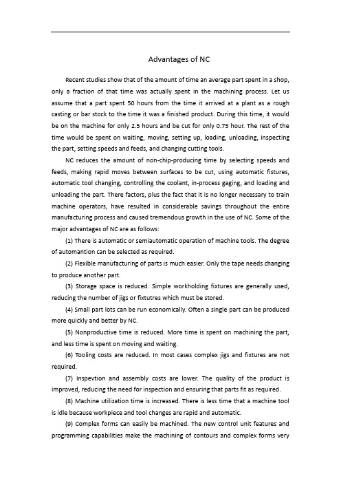
Advantages of NCRecent studies show that of the amount of time an average part spent in a shop, only a fraction of that time was actually spent in the machining process. Let us assume that a part spent 50 hours from the time it arrived at a plant as a rough casting or bar stock to the time it was a finished product. During this time, it would be on the machine for only 2.5 hours and be cut for only 0.75 hour. The rest of the time would be spent on waiting, moving, setting up, loading, unloading, inspecting the part, setting speeds and feeds, and changing cutting tools.NC reduces the amount of non-chip-producing time by selecting speeds and feeds, making rapid moves between surfaces to be cut, using automatic fistures, automatic tool changing, controlling the coolant, in-process gaging, and loading and unloading the part. There factors, plus the fact that it is no longer necessary to train machine operators, have resulted in considerable savings throughout the entire manufacturing process and caused tremendous growth in the use of NC. Some of the major advantages of NC are as follows:(1) There is automatic or semiautomatic operation of machine tools. The degree of automantion can be selected as required.(2) Flexible manufacturing of parts is much easier. Only the tape needs changing to produce another part.(3) Storage space is reduced. Simple workholding fixtures are generally used, reducing the number of jigs or fixtutres which must be stored.(4) Small part lots can be run economically. Often a single part can be produced more quickly and better by NC.(5) Nonproductive time is reduced. More time is spent on machining the part, and less time is spent on moving and waiting.(6) Tooling costs are reduced. In most cases complex jigs and fixtures are not required.(7) Inspevtion and assembly costs are lower. The quality of the product is improved, reducing the need for inspection and ensuring that parts fit as required.(8) Machine utilization time is increased. There is less time that a machine tool is idle because workpiece and tool changes are rapid and automatic.(9) Complex forms can easily be machined. The new control unit features and programming capabilities make the machining of contours and complex forms veryeasy.(10) Parts inventory is reduced. Parts can be made as required from the information on the punched tape.Since the first industrial revolution, about 200 years age, NC has had a significant effect on the industrial world. The developments in the computer and NC have extended a person’s min d and muscle. The NC unit takes symbolic input and changes it to useful output, expanding a person’s concepts into creative and productive results. NC technology has made such rapid advances that it is being used in almost every area of manufacturing, such as machining, welding, pressworking, and assembly.If industry’s planning and logic are good, the second industrial revolution will have as much or more effect on society as the first industrial revolution had. As we progress through the various stages of NC, it is the entire manufacturing process which must be kept in mind.Computer-assisted manufacturing (CAM) and computer-integrated machining (CIM) are certainly where the future of manufacturing lies, and considering the developments of the past, it will not be too far in the future before the automated factory is a reality.Developed originally for use in aerospace industries, NC is enjoying widespread acceptance in manufacturing. The use of CNC machines continues to increase, becoming visible in most metalworking and manufacturing industries. Aerospace, defense contract, automotive, electronic, appliance, and tooling industries all employ numerical control machinery. Advances in microelectronics have lowered the cost of acquiring CNC equipment. It is not unusual to find CNC machinery in contract tool, die, and moldmaking shops. With the advent of low cost OEM(original equipment manufacturer) and retrofit CNC vertical milling machines, even shops specializing in one-of-a-kind prototype work are using CNCs.Although numerical control machines traditionally have been machine tools, bending, forming, stamping, and inspection machines have also been produced as numerical control systems.数控的优点近期研究表明,在加工零件时,只有一少部分时间真正用于加工工件。
- 1、下载文档前请自行甄别文档内容的完整性,平台不提供额外的编辑、内容补充、找答案等附加服务。
- 2、"仅部分预览"的文档,不可在线预览部分如存在完整性等问题,可反馈申请退款(可完整预览的文档不适用该条件!)。
- 3、如文档侵犯您的权益,请联系客服反馈,我们会尽快为您处理(人工客服工作时间:9:00-18:30)。
外文翻译专业机械设计制造及其自动化学生姓名陈曦班级BD机制031学号0320110129指导教师刘道标.模具数控加工计算机辅助刀具选择研究耿铁段修涛译引言数控加工中包括刀具轨迹的产生和刀具选择两个关键问题。
前一问题在过去的20 年里得到了广泛而深入地研究,发展的许多算法已在商用CAD/ CAM 系统中得到应用。
目前大多数CAM 系统能够在用户输入相关参数后自动产生刀具轨迹。
比较而言,对以质量、效率为优化目标的刀具选择问题的研究还远未成熟,当前还没有商用CAM 系统能够提供刀具优选的决策支持工具,因而难以实现CAD/ CAM 的自动有机集成。
刀具选择通常包括刀具类型和刀具尺寸。
一般来说,适合一个加工对象的刀具通常有多种,一种刀具又可完成不同的加工任务,所以仅考虑满足基本加工要求的刀具选择是较容易的,尤其对孔、槽等典型几何特征。
但实际上,刀具选择通常和一定的优化目标相联系,如最大切削效率、最少加工时间、最低加工成本、最长使用寿命等,因此刀具选择又是一个复杂的优化问题。
比如模具型腔类零件,由于几何形状复杂(通常包含自由曲面及岛) ,影响刀具选择的几何约束在CAD 模型中不能显式表示,需要设计相应的算法进行提取,因而选择合适的刀具规格及其刀具组合,以提高数控加工的效率与质量并非易事。
模具型腔一般用数控铣的加工方法,通常包括粗加工、半精加工、精加工等工序。
粗加工的原则就是尽最大可能高效率地去除多余的金属,因而希望选择大尺寸的刀具,但刀具尺寸过大,可能导致未加工体积的增多;半精加工的任务主要是去除粗加工遗留下来的台阶;精加工则主要保证零件的尺寸及表面质量。
考虑到目前完全由计算机进行自动选刀还存在一定困难,因而在我们开发的计算机辅助刀具选择(Computer Aided Tool Selection ,CATS)系统中,立足于给用户提供一个辅助决策工具,即粗加工、半精加工、精加工等,真正的决策权仍留给用户,以充分发挥计算机和人的优势。
1 系统基本结构CATS系统的输入为CAD模型,输出为刀具类型、刀具规格、铣削深度、进给量、主轴转速(切削速度) 和加工时间等六个参数(如图1) ,包括刀具类型选择辅助决策工具、粗加工刀具选择辅助决策工具、半精加工刀具选择辅助决策工具及精加工刀具选择辅助决策工具等。
图1 计算机辅助刀具选择系统的输入与输出鉴于粗加工在型腔加工中的重要地位(通常为精加工时间的5~10 倍) ,粗加工时系统具有刀具自动优化组合的功能,以提高整体加工的效率。
除了上述决策工具外,系统还具有查看刀具详细规范、根据刀具类型和尺寸推荐加工参数及评估加工时间等功能,最后生成总的刀具选择结果报表(如图2) 。
系统所有的刀具数据及知识均由后台数据库做支持。
图2 计算机辅助刀具选择系统的基本功能与模块2 关键技术及算法1)刀具类型选择根据模具型腔数控加工实践,型腔铣加工的刀具一般分为平头铣刀、圆角铣刀及球头铣刀三种。
设刀具直径为D,圆角半径为r ,当r=0 时为平头铣刀,0<R刀具又可分为整体式和镶片式。
对于镶片式,关键是选取刀片的材质,刀片材质的选择取决于三个要素:被加工工件的材料、机床夹具的稳定性以及刀具的悬臂状态。
系统将被加工工件的材料分为钢、不锈钢、铸铁、有色金属、难切削材料和硬材料等六组。
机床夹具的稳定性分为很好、好、不足三个等级。
刀具悬臂分为短悬臂和长悬臂两种,系统根据具体情况自动推理出刀片材质,决策知识来源于WALTER刀具手册,系统由用户首先交互选择刀具类型。
对镶片式刀具,基于规则自动推理出合适的刀片材质。
例如,如果被加工工件的材料为“钢”,机床夹具的稳定性为很好,刀具悬臂为短悬臂,则刀片材质应为WAP25 。
2)粗加工刀具组合优化型腔粗加工的目的就是最大化地去除多余的金属,通常使用平头铣刀,采取层切的方法。
因此,3D模具型腔的粗加工过程,实际上就是对一系列2.5D模具型腔的加工。
刀具优化的目的就是要寻找一组刀具组合,使其能够以最高的效率切除最多的金属。
刀具组合优化的基本方法如下:a.以一定的步长做一组垂直于进刀方向的搜索平面与型腔实体相交,形成搜索层。
b. 求出截交轮廓。
c. 计算内外环之间或岛与岛之间的关键距离,即影响刀具选择的几何约束,算法流程如图3 所示。
图3 求关键距离算法流程d. 根据合并原则(相邻关键距离相差小于给定阈值) 对搜索层进行合并,确定加工平面和可行刀具集,形成加工层。
e. 确定每一加工层使用的刀具,即型腔加工的刀具组合。
f. 根据刀具推荐的加工参数(切削速度、铣削深度和进给速度) ,计算材料去除.g. 根据加工层实际切除的体积,计算每一加工层的加工时间。
h. 计算型腔总的加工时间和残余体积。
i.对该组刀具组合的总体加工效率进行评估。
j. 重复a~i,直至求出最优的刀具组合。
如以时间为目标,即要求以整个型腔的加工时间t 最短来优化刀具组合。
基于上述方法,可建立如下形式化的优化模型。
MRRi=(dicij)×(Nfz)(切割截面积乘进给率)式中: n —型腔加工层数量; m —每一加工层刀具的铣削次数; l —每一加工层中的搜索层数量; q —每一加工层可行的刀具数量; h —型腔深度; cij —i 加工层第j 次铣削深度; aj —第j 切割层底面积; vi —i 加工层的铣削体积;MRRi —i 加工层的材料去除率; di —i 加工层的刀具直径; dip —i 加工层可行刀具集合; rik —i 加工层k 搜索层的关键距离;e1 —控制搜索层合并的常数;e2 —控制残余体积的常数;V —型腔体积;DV —残余体积; N —主轴转速; f —刀具每齿进给量; z —刀具齿数。
考虑到不同的搜索平面步长会产生不同的加工层,从而导致不同的加工时间和残余体积,因此有时尽管总的加工时间较短,但残余体积可能较多。
由此可见,单独以加工时间为目标进行优化有时并不一定科学。
为此,提出了效率系数的概念,综合考虑了加工时间和残余体积的因素,加工时间越短,残余体积越少,则效率系数就越高。
令:上式中前一项反映了加工单位体积的时间系数,其中k =DV/V 为残余体积百分数。
这样,效率系数可定义为q = 1/ Q 。
3)半精加工刀具选择半精加工的主要目的是去除粗加工残留下的台阶状轮廓。
为完全去除台阶,铣削深度必须大于每一台阶到零件表面的距离x。
其算法步骤如下:步骤1 由零件实体模型获得两个相邻截面的表面积以及相应的轮廓长度;步骤2 计算平均轮廓长度;步骤3 计算台阶宽度;步骤4 计算台阶拐角到零件表面的法向距离x ;步骤5 重复步骤1~步骤4 ,决定每一台阶的铣削深度;步骤6 计算刀具直径D,按经验D=x/0.6或根据刀具手册推荐;步骤7 选择铣削深度大于x 的最小刀具。
4)精加工刀具选择5)精加工刀具选择的基本原则是:刀具半径尺寸R 小于零件表面最小的曲率半径一般取R=(0.8~0.9)r。
其算法步骤如下:步骤1 从零件实体模型计算最小曲率半径;步骤2 从刀具库中检索出刀具半径小于计算所得的曲率半径的所有刀具;步骤3 选出满足上述要求的最大刀具;步骤4 如果所有刀具大于最小的曲率半径,选择最小的作为推荐刀具。
3 系统实施及算例CATS 系统在UG/OPEN API环境下应用C语言开发而成。
后台数据库为Oracle 8i ,利用ODBC编程实现UG与数据库之间的通讯。
所有的刀具数据及知识来自德国WALTER 公司的硬质合金刀具综合样本。
图4为一包含岛及雕塑曲面的模具型腔,根据上文提出的粗加工刀具组合的优化方法,该模具型腔粗加工刀具的优化组合为20,12,8,5。
计算中,工件材料选定为中碳钢,切削速度推荐值为100m/min ,铣削深度为刀具直径的1/ 2 ,进给量根据刀具推荐值由程序自动修正计算。
同时,假定刀具库中现有平头铣刀刀具规格为f3,f4,f5,f6,f8,f10,f12,f16,f20。
同样,根据半精加工和精加工的刀具选择算法,得到的球头铣刀的刀具直径分别为4和3。
图4 包含岛及雕塑曲面的模具型腔4 小结与讨论模具型腔加工的工艺规划通常需要很高的技术与经验,准备NC 数据的时间几乎和加工时间一样多。
因此,自动产生型腔加工的工艺计划及NC加工指令的需求就显得愈加迫切。
本文系统研究了模具型腔工艺规划中的刀具选择问题,提出了模具型腔粗加工、半精加工、精加工刀具选择的原则和方法,构造了相应的实现算法,并在UG/OPEN API环境下进行了初步编程实现,开发了CATS原型系统。
在刀具类型和规格确定的基础上,系统还可根据刀具手册推荐加工参数(切削速度、铣削深度、进给量等) ,对相应的加工时间进行评估。
其最终目的是真正实现CAD/CAM的集成,继而通过后处理产生数控加工指令。
目前CATS系统的界面还是独立于UG的CAM界面,CATS 的策结果还需要用户重新输入到CAM。
需要指出的是,要提高模具型腔的总体加工效率,需要从粗加工、半精加工、精加工的整体上考虑,进行多目标组合优化,这将是我们下一步要进行的工作。
Mould&Die NC computer-aided Tool of SelectionGeng TieState Key Lab.of Mould&Die Technology,HuaZhong University of Science and TechnologyWuhan 430074 ,ChinaIntroductionNC machining tool path generation and tool selection, including the two key issues. Before a problem in the past 20 years has been wide-ranging and in-depth study, Many algorithms for the development of CAD / CAM system has been applied in the business. Most CAM systems to the user input parameters with automatic tool path. Comparatively speaking, the quality, efficiency and optimization tool of choice is far from mature. Currently no commercial CAM system optimization tool can provide decision support tools. it is difficult to achieve automatic CAD / CAM integrated. Tools typically include tools and tool type size. In general, usually for a processing tool targeting a variety of different processing tasks as well as the completion of a tool. Therefore, considering only meet the basic requirements of the tool selection process is relatively easy, particularly for the holes, ducts, etc. typical geometric features. But in reality, and we usually choose the optimal tool goals, such as the most efficient cutting, processing time at least, the lowest manufacturing cost, and the longest life expectancy, and so on tool selection is a complex optimization problems. For example, die parts, complex geometric shapes (usually free surface and Island) Tool choices affect the geometric constraints in CAD model can not explicit that it is necessary to design appropriate extraction algorithm, choose the appropriate tools and tool specifications portfolio to improve the efficiency and quality of NC is not an easy task.NC general cavity with the processing methods, including extensive and usually, semi-finishing and finishing processes. Snag is the principle of maximum extent possible the efficient removal of excess metal and thereforewish to opt for large size of the tool, But cutter size is too large, might not lead to an increase in processing volume; the main task is getting extensive and semi-finished stage left; finished the main components of the size and surface quality assurance. Taking into account the current election entirely by the computer automatically knife there are still certain difficulties, therefore, in our development of the computer-aided tool selection (Computer Aided Tool Selection, CATS) system, based on the users to provide a decision-support tool, roughing, semi-finishing and finishing. the real decision-making power is left to users, and to bring into full play the advantages of computer.1.System structure.CATS system for CAD model input, output types of tools, tool specifications Milling depth, feed, Spindle Speed (Speed) and the processing time of six parameters (Figure 1). Tool types of options, including decision-support tool, tool selection decision-support tool for roughing. tool selection decision-support tool for semi-finishing and finishing tool selection decision-making tools.Figure 1 computer-aided tool selection of input and outputGiven extensive and important position in the cavity (usually 5-10 times finishing time). snag when the system is automatically optimized combination of functional tool to enhance overall processing efficiency. In addition tothe above decision-making tools, the system also has a detailed standardized tools to detect, According to the recommendation of processing parameters and the size and type of tool to assess the function of processing time. Tool choice of the final total returns generated (Figure 2). Tool System data and knowledge are all in support of the background database.Figure 2 CAD tool selection and the basic function modules2 key technology and algorithms1) Tools for choiceAccording die NC practice, the tool generally consists of Milling Cutter peace. Fillet cutter and the cutter ball three. Based tool diameter D, the radius r, r = 0 when the crew cutter. 0<R tools can be divided into the overall style and framed chip. Tipped for the ceremony, the key is to select material blades, blade materials are determined by three factors : the workpiece material, Machine tool fixture and the stability of the cantilever. Workpiece material will be processed into steel, stainless steel, cast iron, nonferrous metals, materials and other hard-to-cut materials and hardware six. Stability jig into the well, less than three grades. Cantilever Tool cantilevered into short and long cantilever two, the system automatically inducted blade material under specific circumstances. WALTER Tool knowledge comes from the decision-making manuals, system users to choose the first interactive tool types. Tipped Tools of the rule-based Automated Reasoning blades suitable material. For example, if the workpiece material as "steel", the stability of the fixture good tool for short cantilever cantilever. Blade material will be WAP25.2) Portfolio Optimization Tool snagThe objective is to maximize the cavity snag in the removal of excess metal, used Ping Cutter and take all the layers. Therefore, the 3D die roughing process is actually a series of 2.5D die for processing. Optimization ToolTool Group's goal is to find a combination that will enable it to the highest removal efficiency of most metals. The basic approach is as follows : Portfolio Optimization ToolA.To do a certain step in the direction perpendicular to the feed cavitysearch plane and entities intersect, the formation search layer.B.Deadline for submission of outline obtained.C. Calculation link between or outside of critical distance between the islands, the choice of tools to influence the geometric constraint, the algorithm shown in figure 3.Figure 3 key demand from the algorithm.D. Under this principle (the distance between adjacent key difference is less than a given threshold) level of the search for a merger Plane processing and identify viable tool sets, forming layers.E. Each layer processing tool used to determine that the combination of the tool cavity.F. According to the recommended processing tool parameters (cutting speed, feed rate and depth of milling), material removal rate calculation.G. According to the actual removal of the layer processing volume, the processing time is calculated for each layer processing.H. Calculate the total processing time and residual volume cavity.I. The overall composition of this group processing efficiency assessment tool.J. A~i repeated until the optimal combination of the tool. If time goal that the processing time t required for the entire cavity tool to optimize thecombination of the shortest. Based on the above methodology, we can establish the following formal optimization model.MRRi=(dicij)×(Nfz) (X cross-sectional area of cutting feed rate)Where : n-layer processing cavity volume; M-layer processing each of the milling cutter number; l-processing layer in the search each layer volume; q-layer processing every tool possible number; h-cavity depth; cij -i time processing layer j Milling depth; aj - j cutting area of the base layer; vi -i processing volume ;MRRi -i milling layer, layer of material removal; di -i layer processing tool diameter; -i processing layer dip viable tool set; rik -i processing layer k ;e1 search of the key distance-control layer with a constant search; e2 - residual volume control constants; V-cavity volume ;DV - residual volume; N-spindle speed; f-cutter feed per tooth; z-cutter teeth. Plane taking into account the different steps in the search process will produce different levels, resulting in the processing time and residual volume, So sometimes, even though total processing time shorter, but more likely to residual volume. This shows that the target of a separate optimization of processing time are not necessarily science. Therefore, the coefficient of efficiency of the concept, considering the processing time and the residual volume, the processing time is shorter. less residual volume, the higher the efficiency coefficient. Possession :On a middle-processing unit volume reflects the time factor, k =DV/V percentage of residual volume. Thus, the efficiency coefficient defined as q = 1/ Q.3) Semi-finished Tool SelectionThe main purpose is to remove semi-finished roughing the residue level contour shape. For the complete removal of height, depth milling the surface must be greater than the distance between each level of x components. Algorithm steps are as follows :Step 1 model will have two parts from the adjacent section and the corresponding surface contour length;Step 2 calculation of the average length profile;Step 3 calculating height width;Step 4 Calculation of the corner to level the surface of the parts to distance x law;Step 5 Repeat steps from 1 to 4 steps, each step of the decision Milling depth; Step 6 curve of the diameter D, D=x/0.6 Tools manual or recommended by experience;Step 7 x greater than the minimum depth of choice milling cutter.4) finished Tool SelectionThe basic principle is : finishing tool selection tool radius R size smaller than the smallest curvature radius r surface parts. General admission R = (0.8~0.9) r. The following steps :Step 1 algorithm model from the smallest radius of curvature parts entities; Step 2 retrieved from the database tool cutter radius less than the radius of curvature calculation for all tool;Step 3 select the best tools to meet these requirements;Step 4 : If all the tools than the smallest radius of curvature. Minimum recommended as a tool of choice.3 implementation of the system and examplesCATS system in the C language environment UG/OPEN API was developed. Background for the Oracle 8i database using ODBC programming and database communications between UG. All the data and knowledge from Germany WALTER Tool Company Carbide Tool integrated samples.Figure 4 contains a sculptured surface of the mold cavity and the island, according to the snag in the portfolio optimization tool, The die-extensive portfolio optimization tool for 20,12,8,5. Calculation, the workpiece material selected for carbon steel, cutting speed 100m/min recommended value. Milling depth of two sixth tool diameter, feed rate according to the recommended values from the process tool that automatically calculated. Meanwhile, the assumption that the existing level Cutter Tool Tool Library specifications for f3, f4, f5, f6, f8 and f10, f12. f16, f20. Similarly, semi-finishing and finishing tool selection algorithm, the tool diameter ball mill for 4 and 3.Figure 4 contains the island and sculptured surface of the mold cavity 4 Summary and DiscussionThe planning process usually die of high technology and experience NC data preparation and processing almost as much time. Therefore, the automatic process planning cavity NC machining instructions and it is even more urgent needs. We systematically studied the tool selection process planning die, the die roughing, semi-finishing. and finishing tool of choice for the method, the corresponding algorithm. UG/OPEN environment in a preliminary API programming, and developed a prototype system CATS. Tool to determine the type and specifications based on the recommendation of manual processing system is also under Tools parameters (cutting speed. Milling depth, feed and so on),corresponding to the processing time for assessment. CAD/CAM its ultimate aim is to achieve a truly integrated, and then have to deal with NC machining instructions. At present, the CATS system is independent of the interface UG CAM interface. CATS results of the decisions need to be re-entered into CAM users. What needs to be pointed out is that the mold cavity to enhance the overall processing efficiency, from roughing, semi-finishing. finished the overall consideration for the multi-objective optimization, which will be our next step is to conduct the work.。