P4201A中文资料
OL4201N资料
25.4
12.7
ø5.6
RUBBER HOOD STAINLESS STEEL SLEEVE 7.1 9.0
SMF
6.0 6.35
3.8 2.54
ø0.45
Tolerance = ±0.5 mm (unless noted otherwise) Dimensions in mm.
TERMINAL CONNECTION (BOTTOM VIEW - NOT TO SCALE) #8 #9 LD PD #10 #11 TH T.E.C (+) #7 #6 #5 #4 #3 #2 #1 TH: T.E.C: #12 #13 #14 (-) FIBER Thermistor Thermo-Electric Cooler
Exceeding these maximum ratings could cause immediate damage or lead to permanent deterioration of the device.
Optical and Electrical Characteristics Ta=25°C
Parameter Fiber output power Center wavelength RMS Spectral width Thermistor resistance Symbol Pf λc σ Rth Test Conditions IF(LD)=Ith + 20 mA Pf= 1 mW Pf=1 mW, CW, RMS Min. 1 1470 9.5 Typ. Max. 1490 5 10.5 Units mW nm nm kΩ
CASE
Pin Configuration
Pin Mo. 01 02 03 04 05 06 07 Description Thermo Electric Cooler Anode (+) NC NC NC LD Anode, Case Ground, and internal connect to pin 10 NC PD Cathode Pin No. 08 09 10 11 12 13 14 PD Anode LD Cathode LD Anode, Case Ground, and internal connect to pin 5 Thermistor Thermistor NC Thermo Electric Cooler Cathode (-) Description
P2041A中文资料

Versatile EMI Reduction IC FEATURES• FCC approved method of EMI attenuation• Provides up to 20 dB of EMI suppression• Generates a low EMI spread spectrum clock of the input frequency• Optimized for 25 MHz to 60MHz inputfrequency range• Internal loop filter minimizes externalcomponents and board space• 4 selectable spread ranges• SSON control pin for spread spectrum enable and disable options • Characterizes to work with EMI-Lator®, EMC simulation program.• Low cycle-to-cycle jitter• 3.3 V or 5.0 V operating range• 16 mA output drives• TTL or CMOS compatible outputs• Low power CMOS design• Available in 8 pin SOIC and TSSOPPRODUCT DESCRIPTIONThe P2041 is a selectable spread spectrum frequency modulator designed specifically for PC peripheral and embedded controller markets .The P2041 reduces electromagnetic interference (EMI) at the clock source which provides system wide reduction of EMI of all clock dependent signals. The P2041 allows significant system cost savings by reducing the number of circuit board layers and shielding that are traditionally required to pass EMI regulations.The P2041 uses the most efficient and optimized modulation profile approved by the FCC and is implemented in a proprietary all-digital method. The P2041 modulates the output of a single PLL in order to “spread” the bandwidth of a synthesized clock and, more importantly, decreases the peak amplitudes of its harmonics. This results in significantly lower system EMI compared to the typical narrow band signal produced by oscillators and most frequency generators. Lowering EMI by increasing a signal’s bandwidth is called “spread spectrum clock generation”.APPLICATIONSThe P2041 is targeted towards the embedded controller market and PC peripheral markets including scanners, MFP’s, printers, PDA, IA , and GPS devices.Figure 1 – P2041 Pin DiagramXIN/CLKXOUTSR1VSSVDDSR0ModOUTSSONMay, 2002 PulseCore – A Division of Alliance SemiconductorFigure 2 – P2041 Block DiagramTable 1 - Spread Range SelectionSR1 SR0 Spreading Range Modulation rate0 0 +/- 1.50% (Fin/40)*34.72 KHz0 1 +/- 2.50% (Fin/40)*34.72 KHz1 0 +/- 0.50% (Fin/40)*34.72KHz**1 1 +/- 1.00% (Fin/40)*34.72KHz****NOTE: These settings are not recommended for 5.0V OperationPIN DESCRIPTIONPIN # Name Type Description1 XIN/CLK I Connect to crystal or externally generated clock signal.2 XOUT I Connect to crystal. No connect if externally generated clock signal is used.3 SR1 I Digital logic input used to select Spreading Range (see Table 1). This pinhas an internal pull-up resistor.4 VSS P Ground Connection. Connect to system ground.5 SSON I Digital logic input used to enable Spread Spectrum function (Active Low).Spread Spectrum function enable when low. This pin has an internal pull-low resistor.6 ModOUT O Spread Spectrum Clock Output.7 SR0 I Digital logic input used to select Spreading Range (see Table 1). This pinhas an internal pull-up resistor.8 VDD P Connect to +3.3V or +5.0VMay, 2002 PulseCore – A Division of Alliance SemiconductorSPREAD SPECTRUM SELECTIONTable 1 illustrates the possible spread spectrum options. The optimal setting should minimize system EMI to the fullest without affecting system performance. The spreading is described as a percentage deviation of the center frequency (Note: the center frequency is the frequency of the external reference input on CLKIN, Pin 1).Example of a typical printer or scanner application that operates on a clock frequency of 40 MHz:A spreading selection of SR1=1 and SR0=1 provides a percentage deviation of +/-1.00%* (see Table 1) of F cen. This results in the frequency on ModOUT being swept from 40.40 MHz to 39.60 MHz at a modulation rate of 40/40*34.72=34.72 KHz (see Table 1). This particular example (see Figure 3) given here is a common EMI reduction method for scanners and has already been implemented by most of the leading manufacturers.NOTE: Spreading range selection varies from different system manufacturers and their designs. The spreading range of P2041 can be set to +/-2.5% when working with certain scanner model.Figure 3 - P2041 Application Schematic for Flat-Bed ScannerMay, 2002 PulseCore – A Division of Alliance SemiconductorEMC SOFTWARE SIMULATIONBy using PulseCore Semiconductor, Inc.’s proprietary EMC simulation software – EMI-lator®, radiated system level EMI analysis can be made easier to allow a quantitative assessment on PulseCore’s EMI reduction products. The simulation engine of this EMC software has already been characterized to correlate with the electrical characteristics of PulseCore EMI reduction IC’s. below is an example of the simulation result. Please visit our web site at for information on how to obtain a free copy and demonstration of EMI-lator®.Figure 4 - Simulation Result from EMI-lator®May, 2002 PulseCore – A Division of Alliance SemiconductorABSOLUTE MAXIMUM RATINGSSymbol Parameter Rating UnitV DD, V IN Voltage on any pin with respect to GND -0.5 to +7.0 VT STG Storage Temperature -65 to +125 ºCT A Operating Temperature 0 to +70 ºCDC ELECTRICAL CHARACTERISTICSSymbol Parameter Min Typ Max UnitV IL Input Low Voltage GND – 0.3 - 0.8 V V IH Input High Voltage 2.0 - V DD + 0.3 V I IL Input Low Current (pull-up resistor oninputs SR0, 1)- - -35 µAI IH Input High Current (pull-down resistoron input SSON)- - 35 µAI XOL XOUT Output Low Current(@ 0.4V, V DD = 3.3V)- 3 - mAI XOH XOUT Output High Current(@ 2.5V, V DD = 3.3V)- 3 - mAV OL Output Low Voltage(V DD=3.3V, I OL = 20 mA)- - 0.4 VV OH Output High Voltage(V DD=3.3V, I OH = 20 mA)2.5 - - VI DD Static Supply Current - 0.6 - mAI CC Dynamic Supply Current(3.3V and 15 pF loading)7 8.6 10 mA V DD Operating Voltage 2.7 3.3 5.5 V t ON Power Up Time(First locked clock cycle after power up)- 0.18 - mS Z OUT Clock Output Impedance - 50 - ΩAC ELECTRICAL CHARACTERISTICSSymbol Parameter Min Typ Max Unit f IN Input Frequency 25 40 60 MHzt LH Note 1 Output Rise Time(measured at 0.8V to 2.0V)0.7 0.9 1.1 nst HL Note 1 Output Fall Time(measured at 2.0V to 0.8V)0.6 0.8 1.0 nst JC Jitter (cycle to cycle) - - 360 pst D Output Duty Cycle 45 50 55 % Note1: t LH and t HL are measured into a capacitive load of 15pFMay, 2002 PulseCore – A Division of Alliance SemiconductorMay, 2002 PulseCore – A Division of Alliance SemiconductorFigure 5 - Mechanical Package Outline (8 Pin SOIC)Figure 6 - Mechanical Package Outline (8 Pin TSSOP)L o t #Y W WINCHES MILLIMETERS SYMBOL MIN NOR MAX MIN NOR MAXA0.057 0.064 0.071 1.45 1.63 1.80 A10.004 0.007 0.010 0.10 0.18 0.25 A20.053 0.061 0.069 1.35 1.55 1.75 B0.012 0.016 0.020 0.31 0.41 0.51 C0.004 0.006 0.001 0.10 0.15 0.25 D0.186 0.194 0.202 4.72 4.92 5.12 E0.148 0.156 0.164 3.75 3.95 4.15 e0.050 BSC 1.27 BSC H0.224 0.236 0.248 5.70 6.00 6.30 L0.012 0.020 0.028 0.30 0.50 0.70 a0° 5° 8° 0° 5° 8° Note: Controlling dimensions are millimeters.INCHES MILLIMETERSSYMBOL MIN NOR MAX MIN NOR MAXA- - 0.047 - - 1.10 A10.002 - 0.006 0.05 - 0.15 A2 0.031 0.039 0.041 0.80 1.00 1.05 B0.007 - 0.012 0.19 - 0.30 C0.004 - 0.008 0.09 - 0.20 D0.114 0.118 0.122 2.90 3.00 3.10 E0.169 0.173 0.177 4.30 4.40 4.50 e0.026 BSC 0.65 BSC H0.244 0.252 0.260 6.20 6.40 6.60 L0.018 0.024 0.030 0.45 0.60 0.75 a0° - 8° 0° - 8° Note: Controlling dimensions are millimeters.ORDERING INFORMATIONOrdering Number Marking Package Type TemperatureP2041A-08ST P2041A 8 PIN SOIC, TUBE 0°C TO 70°CP2041A-08SR P2041A 8 PIN SOIC, TAPE & REEL 0°C TO 70°CP2041A-08TT P2041A 8 PIN TSSOP, TUBE 0°C TO 70°CP2041A-08TR P2041A 8 PIN TSSOP, TAPE & REEL 0°C TO 70°C"Licensed under U.S. Patent Nos. 5,488,627 and 5,631,920"May, 2002 PulseCore – A Division of Alliance Semiconductor。
GP-4201 4301TM 安装指南说明书

GP-4201TM/4301TM安装指南在使用产品前请务必阅读所附的“警告/注意信息”。
目录装箱单. . . . . . . . . . . . . . . . . . . . . . . . . . . . . . . . . . . . . . . . . . . . . . . . . . . . . . . 2关于手册. . . . . . . . . . . . . . . . . . . . . . . . . . . . . . . . . . . . . . . . . . . . . . . . . . . . . 3电气规格. . . . . . . . . . . . . . . . . . . . . . . . . . . . . . . . . . . . . . . . . . . . . . . . . . . . . 4部件名称和功能. . . . . . . . . . . . . . . . . . . . . . . . . . . . . . . . . . . . . . . . . . . . . . . . 4串口. . . . . . . . . . . . . . . . . . . . . . . . . . . . . . . . . . . . . . . . . . . . . . . . . . . . . . . . . 6安装. . . . . . . . . . . . . . . . . . . . . . . . . . . . . . . . . . . . . . . . . . . . . . . . . . . . . . . . . 81. 安装要求 . . . . . . . . . . . . . . . . . . . . . . . . . . . . . . . . . . . . . . . . . . . . . . . . . 82. 面板开孔尺寸. . . . . . . . . . . . . . . . . . . . . . . . . . . . . . . . . . . . . . . . . . . . . . 93. 安装步骤 . . . . . . . . . . . . . . . . . . . . . . . . . . . . . . . . . . . . . . . . . . . . . . . . 10接线. . . . . . . . . . . . . . . . . . . . . . . . . . . . . . . . . . . . . . . . . . . . . . . . . . . . . . . . 121. 电源线规格 . . . . . . . . . . . . . . . . . . . . . . . . . . . . . . . . . . . . . . . . . . . . . . 122. 电源接头规格. . . . . . . . . . . . . . . . . . . . . . . . . . . . . . . . . . . . . . . . . . . . . 133. 如何连接电源线. . . . . . . . . . . . . . . . . . . . . . . . . . . . . . . . . . . . . . . . . . . 134. 接线注意事项. . . . . . . . . . . . . . . . . . . . . . . . . . . . . . . . . . . . . . . . . . . . . 14 USB电缆紧固夹 . . . . . . . . . . . . . . . . . . . . . . . . . . . . . . . . . . . . . . . . . . . . . . 151. 安装USB电缆紧固夹 . . . . . . . . . . . . . . . . . . . . . . . . . . . . . . . . . . . . . . 152. 取下USB电缆紧固夹 . . . . . . . . . . . . . . . . . . . . . . . . . . . . . . . . . . . . . . 17相关标准. . . . . . . . . . . . . . . . . . . . . . . . . . . . . . . . . . . . . . . . . . . . . . . . . . . . 18装箱单请确认产品包装中包含下述所有内容:1显示模块(1)2主机模块(1)3套筒扳手(1)4USB电缆紧固夹Type A(1端口)(1)5止动销(1)6DC电源接头(1)7显示模块安装螺帽(1个,已装在显示模块上)8GP-4201TM/4301TM安装指南 (1)<本指南>9警告/注意信息(1)关于手册本手册介绍接线和安装步骤。
XL4201 中文规格书

150KHz 40V 3A 开关电流自带恒流环路降压型DC-DC 转换器 XL4201特点n 8V 到40V 宽输入电压范围 n 输出电压从1.25V 到37V 可调 n 最小压差0.3V n 固定150KHz 开关频率 n 最大3A 开关电流 n 内置功率MOSn 出色的线性与负载调整率 n 内置恒流环路 n 内置频率补偿功能 n 内置输出短路保护功能 n 内置输入过压保护功能 n 内置热关断功能 n 推荐输出功率小于13Wn SOP8-EP 封装应用n 车载充电器 n 电池充电器 n LCD 电视与显示屏 n 便携式设备供电 n 通讯设备供电 n 降压恒流驱动 n 显示器LED 背光 n 通用LED 照明描述XL4201是一款高效降压型DC-DC 转换器,可工作在DC8V 到40V 输入电压范围,低纹波,内置功率MOS 。
XL4201内置固定频率振荡器与频率补偿电路,简化了电路设计。
PWM 控制环路可以调节占空比从0~100%之间线性变化。
内置输出过电流保护功能。
内部补偿模块可以减少外围元器件数量。
图1.XL4201封装150KHz 40V 3A开关电流自带恒流环路降压型DC-DC转换器XL4201引脚配置图2. XL4201引脚配置表1.引脚说明引脚号引脚名称引脚描述1,6 NC 无连接。
2 SW 功率开关输出引脚,SW是输出功率的开关节点。
3 GND 接地引脚。
4 FB 反馈引脚,通过外部电阻分压网络,检测输出电压进行调整,参考电压为1.25V。
5 CS 输出电流检测引脚(IOUT=0.11V/RCS)。
7 VC 内部电压调节旁路电容,需要在VC与VIN之间并联1uF电容。
8 VIN 输入电压,支持DC8V~40V宽范围电压操作,需要在VIN与GND 之间并联电解电容以消除噪声。
背部焊盘为SW150KHz 40V 3A开关电流自带恒流环路降压型DC-DC转换器XL4201 方框图图3. XL4201方框图典型应用(车载充电)图4. XL4201系统参数测量电路150KHz 40V 3A开关电流自带恒流环路降压型DC-DC转换器XL4201典型应用(降压LED恒流驱动)ILED=0.11V/RCS图5.XL4201系统参数测量电路(LED恒流驱动)订购信息产品型号打印名称封装方式包装类型XL4201E1 XL4201E1 SOP8-EP 2500只每卷XLSEMI无铅产品,产品型号带有“E1”后缀的符合RoHS标准。
MSK4201中文资料

PWM INPUT - Is a TTL compatible input pin for providing the PWM signal to modulate the output switches. The duty cycle can be between 0% (DC Low) and 100% (DC High). See typical system operation notes.
(315) 701-6751
FEATURES:
Low Cost Complete H-Bridge 28 Volt, 5 Amp Capability, 75 Volt Maximum Rating Self-contained Smart Lowside/Highside Drive Circuitry Internal Deadtime Generation, Shoot-through Protection Output Disable/Shutdown Capability Isolated Case Allows Direct Heatsinking Four Quadrant Operation, Torque Control Capability Available Fully Screened To MIL-H-38534
Peak Output Current 37A ○
○
○
○
○
○
○
○
○
○
○
○
○
○
○
Output Voltage Range GND-2V min. To V+ max.
PT4201
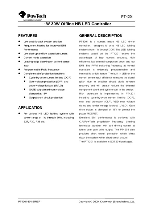
1W-30W Offline HB LED ControllerFEATURESz Low cost fly-back system solution z Frequency Jittering for Improved EMI Performancez Low start-up and low operation current z Current mode operationz Leading-edge blanking on current sense inputz Programmable PWM frequency zComplete set of protection functions Cycle-by-cycle current limiting (OCP) Over voltage protection (OVP) and under voltage lockout (UVLO) GATE output maximum voltage clamped at 18VOutput short circuit protectionAPPLICATIONz For various HB LED lighting system withpower range of 1W through 30W, including E27, P30, P38 etc.GENERAL DESCRIPTIONPT4201 is a current mode HB LED driver controller , designed to drive HB LED lighting systems from 1W through 30W. The LED lighting systems based on the PT4201 enjoys the advantages of high current accuracy, high efficiency, low external component count and low EMI. The PWM switching frequency at normal operation is externally programmable and trimmed to a tight range. The built in LEB on the current sense input efficiently removes the signal glitch due to snubber circuit diode reverse recovery and will greatly reduce the external component count and system cost in the design. Rich protection is implemented in PT4201 including cycle-by-cycle current limiting (OCP), over load protection (OLP), VDD over voltage clamp and under voltage lockout (UVLO). Gate drive output is clamped at 18V to protect the power MOSFET.Excellent EMI performance is achieved with C.R.PowTech proprietary frequency Jittering technique together with soft driving control at totem pole gate drive output. The PT4201 also provides short circuit protection which shuts down the system when short circuit occurs. The PT4201 is available in SOT23-6 packages .TYPICAL APPLICATIONS。
BD4201FV资料
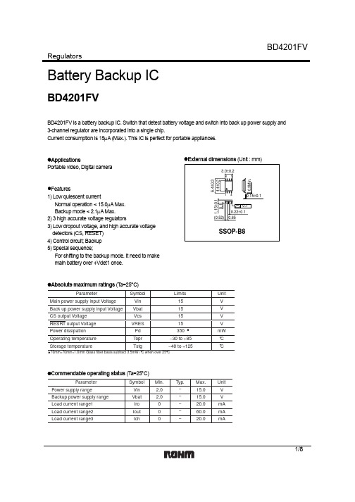
Regulators1/8Battery Backup ICBD4201FVBD4201FV is a battery backup IC. Switch that detect battery voltage and switch into back up power supply and 3-channel regulator are incorporated into a single chip.Current consumption is 15µA (Max.). This IC is perfect for portable appliances.z ApplicationsPortable video, Digital cameraz Features1) Low quiescent currentNormal operation < 15.0µA Max. Backup mode < 2.1µA Max.2) 3 high accurate voltage regulators3) Low dropout voltage, and high accurate voltagedetectors (CS, RESET)4) Control circuit; Backup5) Special sequence;For shifting to the backup mode. It need to makemain battery over +Vdet1 once.z External dimensions (Unit : mm)z Absolute maximum ratings (Ta=25°C)z Commendable operating status (T a=25°C)Regulators2/8z Block diagramV c hR E S E TV b a tV s sV r oV o u tV i n C SFig. 1Regulatorsz Circuit around pin3/8Regulatorsz Electrical characteristics (Unless otherwise specified Vin=6V, T a=25°C)4/8Regulators5/8z Measurement circuitFig.2z Application circuitRESETFig.3Regulators6/8z Note for use1. The application circuit is recommended for use. Make sure to confirm the adequacy of the characteristics. Whenusing the circuit with changes to the external circuit constants, make sure to leave an adequate margin for external components including static and transitional characteristics as well as dispersion of the IC. 2. Operation supply voltage rangeThe circuit functionality is guaranteed within the operation of ambient temperature range, as long as it is within the operation supply voltage range. The standard of electrical characteristic values cannot be guaranteed at other voltages in the operating range, however, the variation will be small.3. The regulator output circuit of this IC does not include protect circuit for the unusual situations such as over voltagecurrent protection, short detect circuit and thermal shut-down circuit.Therefore, this IC might be broken down when it is loaded exceeding the package power, or when it is shorted. T o design application circuit, please deal it with enough consideration. 4. Oscillation stopper of output and bypass capacitorPlease put into capacitor to stop oscillation between output pin and GND.It has a possibility of oscillation if capacitance is changed due to temperature range, and it recommends to use small tantalum electrolytic capacitor of equivalents serial resistor (ESR).If extremely big capacitor is used, it may have a case to occur oscillation of low frequency .Please confirm this point. And it recommend to put into bypass capacitor into the nearest position between input pin and GND.5. For the grounding shown in the application circuit, wire every ground to GND terminal in a short pattern arrange-ment to avoid electrical disturbance.6. This product is produced with strict quality control, but might be destroyed in using beyond absolute maximumratings is considered. Open IC destroyed a failure mode cannot be defined (I like short mode, or open mode).Therefore, physical security countermeasure, like fuse, is to be given when a specific mode to be beyond absolute maximum ratings is considered.7. Mal-function may happen when the device is used in the strong electromagnetic field.8.Recommended to put DIODE for protection purpose in case of output pin connected with large load of inpedanceor reserve current occurred at initial and output off.OUTPUT PIN(Example)9. This IC is monolithic IC which (as shown in Figure-4) has P+ isolation in the P substrate and between the various pins. A P-N junction is formed from this P layer and N layer of each pin. For example, the relation between each potentials is as follows;(When GND > pinB and GND > pinA, the P-N junction operates as parasitic diode.) (When > pinB > GND > pinA, the P-N junction operates as parasitic transistor.) Parasitic diodes can occur inevitably in the structure of the IC. The operation of parasitic diodes can result in mutual interference among circuits as well as operation faults and physical damage.Accordingly , Please do not use methods by which parasitic diode operate, such as applying a voltage that is lower than the GND (P substrate) voltage to an input pin.Regulators7/8Fig.4 Simplified structure of IC(Pin A)ResistanceTransistor (NPN)BGND(Pin A)(Pin B)or transistoror transistorz Pin layoutVbat Vro Vin VoutVss Vch CSFig. 5Regulators8/8z Electrical characteristic curvesP o w e r d i s s ip a t i o nTemperature(mW)2550 75 100125150100200300400500( C)Fig.6 Power dissipation curveAppendixAbout Export Control Order in JapanProducts described herein are the objects of controlled goods in Annex 1 (Item 16) of Export Trade ControlOrder in Japan.In case of export from Japan, please confirm if it applies to "objective" criteria or an "informed" (by MITI clause)on the basis of "catch all controls for Non-Proliferation of Weapons of Mass Destruction.Appendix1-Rev1.0。
艾顿保护设备微型电路保护器PLG4,型号及规格说明书

Protective DevicesMiniature Circuit Breakers PLG4, N-leftX.X• T op-quality miniature circuit breakers 1P+N with a width of 1 module unit requiring little space for installation• Contact position indicator red - green • Guide for secure terminal connection • C omprehensive range of accessories for sub-sequent installation • Rated currents up to 40 A • Tripping characteristics B, C• R ated breaking capacity 4.5 kA according to IEC/EN 60898DescriptionSG54112X.X Protective DevicesMiniature Circuit Breakers PLG4, N-leftRated current I n (A)TypeDesignationArticle No.Units perpackage4.5 kA, Characteristic BSG541126PLG4-B6/1N26470012/12010PLG4-B10/1N26470112/12013PLG4-B13/1N26470212/12016PLG4-B16/1N26470312/12020PLG4-B20/1N26472712/12025PLG4-B25/1N26472812/12032PLG4-B32/1N26472912/12040PLG4-B40/1N26474012/1201+N-pole4.5 kA, Characteristic CSG541122PLG4-C2/1N26474112/1204PLG4-C4/1N26474212/1206PLG4-C6/1N26474312/12010PLG4-C10/1N26474412/12013PLG4-C13/1N26474512/12016PLG4-C16/1N26474612/12020PLG4-C20/1N26474712/12025PLG4-C25/1N26474812/12032PLG4-C32/1N26474912/12040PLG4-C40/1N26475012/1201+N-poleX.XProtective DevicesMiniature Circuit Breakers PLG - T echnical DataSpecifi cations | Miniature Circuit Breakers PLGDescription• H igh selectivity between MCB and back-up fuse due to low let-through energy• P rofi le compatible with other devices of the Xpole series, bridging with thePFGM RCD circuit breaker is possible• C olour of the switching toggle according to the performance rating of thecircuit breaker• M eets the requirements of insulation co-ordination, distance between con-tacts > 4 mm, for secure isolation• Rated breaking capacity I cn1 = 3 kA• N-LinksTechnical DataPLGElectricalIEC/EN 60898Design according toCurrent test marks as printed onto the deviceRated voltage U nAC230 VDC48 VRated frequency50/60 HzRated breaking capacityPLG6 6 kAPLG4 4.5 kACharacteristic B, CBack-up fuse>6 kA max. 100 A gL/gG>4.5 kA max. 80 A gL/gGSelectivity class3Endurance electrical components 8,000 operating cyclesMechanicalFrame size45 mmDevice height80 mmDevice width 17.5 mm per pole (1MU for 1p+N)Mounting quick fastening with 2 lock-in positions on DIN rail EN50022 Degree of protection IP20Upper and lower terminals open mouthed/lift terminalsTerminal protection fi nger and hand touch safe, DGUV VS3, EN 50274 Terminal capacity1x (1.5 - 35) mm2 single wire2x (1.5 - 16) mm2 multi wireTerminal cross-section1-16 mm2Connection diagram1-pole + NDimensions (mm)X.XProtective DevicesMiniature Circuit Breakers PLG - T echnical DataLoad rating – Effect of ambient temperature PLG6Permitted permanent load at ambient temperature T (°C) with n devices I DL = I n K T (T) K N (N)Let-through energy PLG6Let-through energy PLG6, Characteristic B, 1+N-poleLet-through energy PLG6, Characteristic C, 1+N-poleLoad Capacity of Series Connected PLG6Effect of ambient temperature (I n = 2-13 A)Effect of ambient temperature (I n = 32, 40 A)Effect of ambient temperature ( I n= 16-25 A)L o a d c a p a c i t y K T [I /I n ]L o a d c a p a c i t y K T [I /I n ]L o a d c a p a c i t y K T [I /I n ]L e t t h r o u g h e n e r g y I 2t [A 2 s e c ]Prospective short-circuit current [A]L e t t h r o u g h e n e r g y I 2t [A 2 s e c ]Prospective short-circuit current [A]L o a d c a p a c i t y f a c t o r K NNumber of devices (n)Ambient temperature T [°C]Protective DevicesMiniature Circuit Breakers PLG - T echnical DataX.XLoad rating – Effect of ambient temperature PLG4Permitted permanent load at ambient temperature T (°C) with n devices I DL = I n K T (T) K N (N)Let-through energy PLG4Let-through energy PLG4, Characteristic B, 1+N-poleLet-through energy PLG4, Characteristic C, 1+N-poleLoad Capacity of Series Connected PLG4Effect of ambient temperature (I n = 2-13 A)Effect of ambient temperature (I n = 32, 40 A)Effect of ambient temperature ( I n= 16-25 A)500300500100015002000300040005000600070001000015000800090004009007008006001500100030002000500040002000090007000100008000600015000300005000060000400007000080000prospektiver Kurzschlußstrom [A]D u r c h l a ße n e r g i e I t [A s e c ]22prospektiver Kurzschlußstrom [A]D u r c h l a ße n e r g i e I t [As e c ]22500300500100015002000300040005000600070001000015000800090004009007008006001500100030002000500040002000090007000100008000600015000300005000060000400007000080000L e t t h r o u g h e n e r g y I 2t [A 2 s e c ]Prospective short-circuit current [A]L e t t h r o u g h e n e r g y I 2t [A 2 s e c ]Prospective short-circuit current [A]L o a d c a p a c i t y f a c t o r K NNumber of devices (n)L o a d c a p a c i t y K T [I /I n ]L o a d c a p a c i t y K T [I /I n ]L o a d c a p a c i t y K T [I /I n ]Ambient temperature T [°C]。