测试系统的组成
测试系统由哪些环节组成
1. 现代机械产品和信息化有何关系?机械产品的灵魂是测试系统,测试系统需要信息化的支持,信息化的两个特点是:一、网络化:协同手段、资源共享协同设计和制造、远程设计与制造、并行设计和制造。
二、数字化:信息化的核心。
在制造领域,它表现在:数字工厂、数字制造、数字装备等,同时,它又能大大提高设备的精确度。
2. 测试系统由哪些环节组成?测试系统包括传感器、信号调理、数据采集、数据处理、显示。
3. 周期信号谱和非周期信号谱有何异同?相同点:都是通过对时域信号进行傅里叶变换得到的,其幅值谱和相位谱的物理意义是一样的。
都是在无限的频带上作傅里叶展开。
不同点:周期信号非周期信号周期T T→∞圆频率ω0=2Л/T ω0 →dω△ω无穷小谱线k.ω0 k.ω0 →ω连续4. 信号量化存在哪些误差?如何减少幅值误差?(1)幅值误差、失真、能量泄露。
(2)1.增大量化时分度的区间个数2.使区间取值接近信号的峰值3.增加A/D的采样位数。
5. 频谱混叠的原因是什么?如何实施抗混叠滤波?(1)折叠频率小于最高分析频率的采集而产生混频,欠采样产生频谱混叠(2)采集前滤去大于fd的,频率——抗混叠滤波,低通滤波频率为0—fd6. 何谓FFT?它主要解决什么问题?(1)FFT,即快速傅氏变换,是离散傅氏变换的快速算法,它是根据离散傅氏变换的奇、偶、虚、实等特性,对离散傅立叶变换的算法进行改进获得的。
(2)离散傅里叶变换(DFT)由于计算量太大,利用一般的计算机计算时需要耗费大量时间,满足不了一般系统的实时性要求。
FFT主要解决的问题是利用快速的算法来实现对信号的傅里叶变换,大大减少了傅里叶变换的计算量。
7. 什么是不失真测试?要满足什么条件?输入输出在时间轴上的的宽度相等,对应高度成比例,只是滞后一个位置t0,或者输入信号的个频率分量通过装置,均应被放大相同的倍数A08. 测试系统主要的静、动态参数包括哪些?静态参数:灵敏度、测量范围、精度、线性度等。
计算机系统组成测试
计算机系统的组成测试一、单选题1.计算机系统包括。
A.硬件系统和数据处理系统B.硬件系统和软件系统C.软件系统和中央处理器D.主机和外部设备2.个人计算机属于。
A.小巨型计算机B.中型计算机C.小型计算机D.微型计算机3.下列说法正确的是。
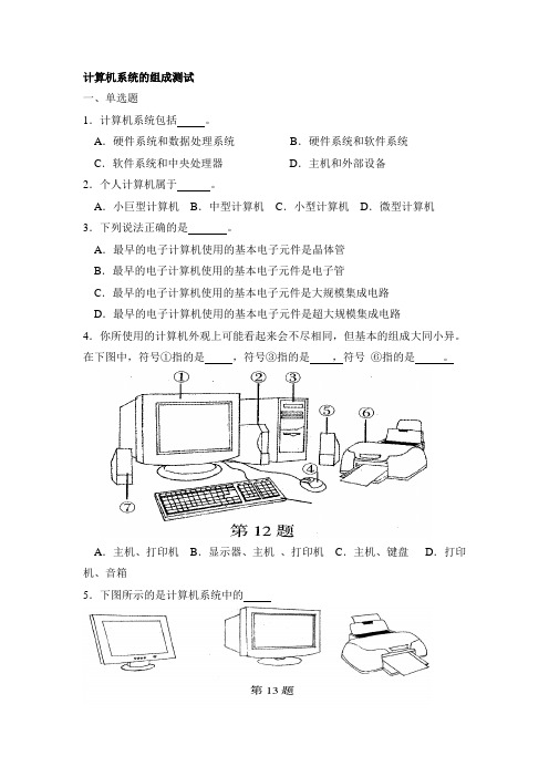
A.最早的电子计算机使用的基本电子元件是晶体管B.最早的电子计算机使用的基本电子元件是电子管C.最早的电子计算机使用的基本电子元件是大规模集成电路D.最早的电子计算机使用的基本电子元件是超大规模集成电路4.你所使用的计算机外观上可能看起来会不尽相同,但基本的组成大同小异。
在下图中,符号①指的是,符号③指的是,符号⑥指的是。
A.主机、打印机B.显示器、主机、打印机C.主机、键盘D.打印机、音箱5.下图所示的是计算机系统中的A.主机和显示器B.显示器C.显示器、主机和打印机D.显示器和打印机5.下列有关计算机的描述中,不正确的是。
A.计算机是信息处理的工具.B.计算机按照人们编写的程序,对输入的数据进行加工处理C.由于计算机智能技术的发展,机器人最终可以代替人类D.计算机的使用可以提高工作效率和改善生活质量6.目前普遍使用的微型计算机所用的基本电子元件是。
A.电子管B.晶体管C.小规模集成电路D.大规模、超大规模集成电路7.下列说法错误的是。
A.使用计算机应遵守与信息技术有关的道德规范B.开机时要先开显示器,后开主机;关机的顺序与开机的顺序相反C.为了提高工作效率,可以再开机状态下插拔各种接口卡D.选择计算机的工作环境要注意:温度、湿度、摆放位置、防尘8.在某软件的使用手册或包装盒上,写着如下说明,其中是对硬件环境的要求。
某软件要求的系统配置为:①PentiumⅡ450,PentiumⅢ500的CPU ②64M以上内存③950M以上硬盘空间④4倍速以上CDROM驱动器⑤支持DireetDraw显示卡⑥鼠标⑦声卡,支持DireetSound的音效卡⑧Windows95/98/ME/XP简体中文版A.①⑤⑥⑦B.①②③④⑤C.⑤⑥⑦⑧D.①②③④⑤⑥⑦9.计算机系统中的鼠标是。
爆炸测试技术

∆h ∆h δ= × 100% ym
∆h
— 正、反行程输出最大误差
ym — 仪器满量程输出
图2.12 迟滞误差
16
BEIJING INSTITUTE OF TECHNOLGY
爆炸测试技术
EXPLOSION TESTING TECHNIQUE
第二章 测试系统
(4) 重复性(重复性误差)
当测试系统按同一方向(单调增大或单调减小) 当测试系统按同一方向(单调增大或单调减小)连续做全 量程多次测量时,所得的标定曲线往往不能完全重合, 量程多次测量时,所得的标定曲线往往不能完全重合,表征 标定曲线不重叠程度的静态特性即为重复性。 标定曲线不重叠程度的静态特性即为重复性。
r=± ∆m × 100% ym
∆m —多次测量所得输出量间的最大偏差
ym — 仪器满量程输出
图2.13 重复性误差
17
BEIJING INSTITUTE OF TECHNOLGY
爆炸测试技术
EXPLOSION TESTING TECHNIQUE
第二章 测试系统
由于重复性误差具有随机性,Δm值与重复次数有关, 由于重复性误差具有随机性,Δm值与重复次数有关,可 值与重复次数有关 采用下式求得更合理的重复性误差值。 采用下式求得更合理的重复性误差值。
爆炸测试技术
EXPLOSION TESTING TECHNIQUE
第二章 测试系统
加速度传感器的动态响应可以用二阶方程式表达:
d2 y dy m 2 + µ + ky = f (t) dt dt
式中:m —质量,μ—阻尼, k —弹性力
22
BEIJING INSTITUTE OF TECHNOLGY
NI Hil测试系统介绍及组成说明书
Architectures for Implementing a Hardware-in-the-Loop SystemOverviewYou can test embedded control systems more efficiently with the powerful method of hardware-in-the-loop (HIL) simulation. Safety, availability, or cost considerations can make it impractical to perform all the necessary tests with the complete embedded control system. Using HIL simulation, you can simulate the parts of the system that pose these challenges. By thoroughly testing the embedded control device in a virtual environment before proceeding to real-world tests of the complete system, you can maintain reliability and time-to-market requirements in a cost-effective manner even as the systems you are testing become more complex.ContentsComponents of an HIL Test System (2)Hardware Fault Insertion (2)Testing Multi-ECU Systems (2)Additional Processing Power—Distributed Processing (3)Simplified Wiring—Distributed I/O (4)Implementing HIL Test Systems (4)Next Steps (5)Components of an HIL Test SystemAn HIL test system consists of three primary components: a real-time processor, I/O interfaces, and an operator interface. The real-time processor is the core of the HIL test system. It provides deterministic execution of most of the HIL test system components such as hardware I/O communication, data logging, stimulus generation, and model execution. A real-time system is typically necessary to provide an accurate simulation of the parts of the system that are not physically present as part of the test.The I/O interfaces are analog, digital, and bus signals that interact with the unit under test. You can use them to produce stimulus signals, acquire data for logging and analysis, and provide the sensor/actuator interactions between the electronic control unit (ECU) being tested and the virtual environment being simulated by the model. The operator interface communicates with the real-time processor to provide test commands and visualization. Often, this component also provides configuration management, test automation, analysis, and reporting tasks.Figure 1. An HIL test system consists of three primary components: an operator interface, a real-timeprocessor, and I/O interfaces.Hardware Fault InsertionMany HIL test systems use hardware fault insertion to create signal faults between the ECU and the rest of the system to test, characterize, or validate the behavior of the device under these conditions. To accomplish this, you can insert fault insertion units (FIUs) between the I/O interfaces and the ECU to allow the HIL test system to switch the interface signals between normal operation and fault conditions such as a short-to-ground or open circuit.Figure 2. You can use hardware fault insertion to test the behavior of the ECU during signal faults. Testing Multi-ECU SystemsSome embedded control systems, such as an automobile, aircraft, or wind farm, use multiple ECUs that are often networked together to function cohesively. Although each of these ECUs may initially be testedindependently, a system’s integration HIL test sys tem, such as a full vehicle simulator or iron bird simulator, is often used to provide more complete virtual testing. When testing a multi-ECU control system (and even some single ECU control systems), two needs often arise: additional processing power and simplified wiring.Figure 3. Automobiles, aircraft, and wind farms use multiple ECUs. Additional Processing Power—Distributed ProcessingEven with the latest multicore processing power, some systems require more processing power than what is available in a single chassis. To address this challenge, you can use distributed processing techniques to meet the performance requirements of these systems. In very high-channel-count systems, the need is more than simply additional processing power, additional I/O is also necessary. In contrast, systems using large, processor-hungry models often use additional chassis only for the extra processing power, allowing those processors to remain dedicated to a single task for greater efficiency. Depending on how the simulator tasks are distributed, it may be necessary to provide shared trigger and timing signals between the chassis as well as deterministic data mirroring to allow them to operate cohesively.Figure 4. When using multiple chassis for additional processing power, it is often necessary to provide timing and data synchronization interfaces between them.Simplified Wiring—Distributed I/OImplementing and maintaining wiring for high-channel-count systems can pose costly and time-consuming challenges. These systems can require hundreds to thousands of signals be connected between the ECU and the HIL test system, often spanning many meters to compensate for space requirements.Fortunately, deterministic distributed I/O technologies can help you tame these wiring complexities and provide modular connectivity to ECUs, which allows for efficient system configuration modifications. Instead of routing all connections back to a single rack containing one or more real-time processing chassis instrumented with I/O interfaces, you can use deterministic distributed I/O to provide modular I/O interfaces located in close proximity to each ECU without sacrificing the high-speed determinism necessary for accurate simulation of the virtual parts of the system.This approach greatly reduces HIL test system wiring cost and complexity by making it possible for the connections between the ECU and the I/O interfaces to be made locally (spanning less than a meter) while a single bus cable is used to span the additional distance to the real-time processing chassis. Additionally, with the modular nature of this approach, HIL test systems can easily scale, incrementally, from a multi-ECU test system in which all but one of the ECUs are simulated to a complete system integration HIL test system where none of the ECUs are simulated.Figure 5. Deterministic distributed I/O interfaces greatly reduce HIL test system wiring cost and complexity because the connections between the ECU and the I/O interfaces can be made locally. Implementing HIL Test SystemsAfter you have selected the appropriate architecture for your HIL test system, the first step in creating a HIL test system is to select the components that best meet your development requirements. NI provides a wide variety of real-time processing and I/O options for implementing HIL test systems. Because they are all based on open industry standards, you can be assured that they always deliver the latest advances in PC technology to your HIL test system and always meet future test system requirements.The NI HIL platform is open and extensible, which means that it can adapt to changing system requirements. Because of its modular architecture, the NI HIL platform can be easily upgraded with additional functionality, which helps you future proof your test systems and meet the requirements of the most demanding embedded software testing applications. In addition to the widest range of I/O on market, NI offers software tools that help you automate your HIL tests, perform post-processing and report generation, and map test results to requirements. These tools help you perform a wider range of tests earlier in the software development process, which reduces overall development cost while improving product quality.。
作业题1、测试系统的组成是什么各部分的主要作用是什
第12章
传感器的典型应用
1、电涡流式位移传感器是一种非接触式测振传感器, 其基本原理是什么?P186
2、什么是光栅?什么是莫尔条纹?P201
3、磁尺测量装置有那几部分组成?P205 4、什么是压磁效应?压磁式力传感器的工作原理是 什么?P219
5、图中所示为一直流电桥,供电电源电动势 E=3V,R3=R4=100Ω,R1R2为相同型号的电 阻应变片,其电阻均为50Ω,灵敏度系数K=2.0。 两只应变片分别粘贴在等强度梁同一截面的正 反两面。设等强度梁在受力后产生的应变为 5000με,试求此时电桥输出电压U0。
b
R1 R1 R2 R2
6、为什么霍尔元件一般采用N型半导体材料?
7、霍尔灵敏度与霍尔元件厚度之间有什么关系?
第10章 作业
1、热电偶温度传感器的工作原理是什么?
2、热电偶的基本定律有哪些?
3、为什么要对热电偶进行冷端补偿?常用的方法有哪些? 补偿导线的作用是什么?连接补偿导线要注意什么?
4、电阻式温度传感器的工作原理是什么?有几种类型?
5、金属热阻温度传感器常用的材料有哪几种?
第11章 光电式传感器
1、光电效应有哪几种?分别对应什么光电元件? 2、试比较光敏电阻、光电池、光敏二极管的性能差异,简 述在不同场合下应选哪种元件最为合适? 3、简述光电倍增管的工作原理。 4、用光电传感器测转速,试画出其原理结构简图,并说明 其工作原理。
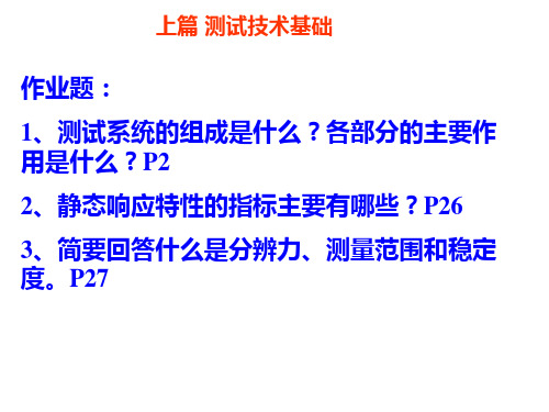
上篇 测试技术基础
作业题:
1、测试系统的组成是什么?各部分的主要作 用是什么?P2
2、静态响应特性的指标主要有哪些?P26 3、简要回答什么是分辨力、测量范围和稳定 度。P27
第5章 电阻应变式传感器
本章作业: 1、什么是应变效应?金属电阻应变片与半导体应变片的工作原理有何异同? 2、试说明电阻应变片有哪些途? 3、采用阻值为120Ω、灵敏度系数K=2.0的金属电阻应变片和阻值为120Ω的固定电阻 组成电桥,供桥电压为4V,并假定负载电阻无穷大。当应变片上的应变分别为1με和 1000με时,试求单臂工作电桥、双臂工作电桥及全桥工作时的输出电压,并比较三种 情况下的灵敏度。 4、采用阻值R=120Ω、灵敏度系数K=2.0的金属电阻应变片与阻值R=120Ω的固定电阻 组成电桥,供桥电压为10V。当应变片应变为1000με时,若要使输出电压大于10mV, 则可采用何种接桥方式(设输出阻抗为无穷大)?
测试系统的组成
测试系统的组成
1、信号检出部分
传感器(Sensor)---- 执行检出功能的器件
信号提取(被测量)、传输(信号变换部分)
选择:测量精度要求、被测量变化范围、被测对象所处的环境条件
以及对传感器体积和整个检测系统的成本等的限制
检测系统中形式是多样、与被测对象关联最密切的部分
2、信号变换部分
检出信号——适合于分析和处理的信号
信号调理电路
阻抗变换---- 输出阻抗很高时;
信号放大---- 输出信号微弱时;
噪声抑制---- 信号淹没在噪声中;
电压/电流(V/A)转换---- 需要电流输出时;
模拟/数字(A/D)转换---- 需要输出数字信号时
3、分析处理部分
不断注入新内容---- 检测系统的研究中心
计算机系统---- 强大问题分析能力、复杂系统的实时控制
自动化、智能化
4、通信接口与总线部分
功能:管理不同系统之间的数据、状态和控制信息的传输和交换
接口--- 分系统和上位机之间/分系统之间交换信息
●2、测试过程和测试系统的组成
●根据测试任务复杂程度的不同,测试系统中传感器、中间变换装置和显示记录装
置等每个环节又可由多个模块组成。
例如,机床轴承故障监测系统中的中间变换装置就由带通滤波器、A/D变换和计算机中的FFT分析软件三部分组成。
土木工程监测技术

土木工程监测技术土木工程监测技术第一章测试技术理论基础测试技术是测量技术和试验技术的总称。
现代测试技术的主要功用:●各种参数的测定;●自动化过程中参数的反馈、调节和自控;●现场实时检测和监控;●试验过程中的参数测量和分析。
测试系统应具有的功能:●将被测对象置于预定状态下;●对信息进行采集、变换、传输;●对信号进行必要的分析、处理和判断;●信号的显示或记录。
现代测试技术的发展趋势:●高精度、小型化和智能化;●新型传感器的研制。
一、测试系统的组成一个测试系统可以由一个或若干个功能单元所组成。
一个功能单元组成的测试系统:弹簧称;温度计。
多个功能单元组成的测试系统:直剪试验计算机测试系统(如图1-1)。
典型的力学测试系统由四大部分组成(如图1-2):荷载系统、测量系统、显示与记录系统。
1、荷载系统荷载系统是使被测对象处于一定的受力状态下,使被测对象(试件)有关的力学量之间的联系充分显露出来,以便进行有效测量的一种专门系统。
地下工程试验采用的荷载系统有:液压式、重力式、杠杆式、弹簧式、气压式、等等。
2、测量系统测量系统由(一次仪表)、中间变换和测量电路(二次仪表)组成。
一次仪表(传感器)把被测量(如力、位移)变成电信号;二次仪表将信号变换、放大、运算,变成易于处理和记录的信号。
不同的传感器要求与其相匹配的二次仪表。
模拟式仪器中包含有抗干扰和滤波器等电路或器件;数字式仪器中包含有抗干扰和滤波器等软件。
3、显示和记录系统它是将信号及其变化过程显示或记录(或存储)下来,是测试系统的输出环节。
数据显示:各种表盘、电子示波器和显示屏;数据记录:函数记录仪、光线示波器、打印机和绘图仪等;数据存储:磁带记录仪、磁盘(硬盘、软盘)等,设备来实现,直剪试验计算。
机辅助测试系统中,以微机屏幕、等作为显示记录设备。
二、测试系统的主要性能指标测试系统的主要性能指标是经济合理地选择测试系统时所必需明确的。
1、测试系统的精度和误差精度:测试系统给出的指示值和被测量的真值的接近程度。
测试系统基本组成

2.2 工程测试中的常用传感器
容计算式为 C 2 x
ln(D / d )
2.2 工程测试中的常用传感器
(3)介质变化型电容式传感器
C 2hx 20(hhx) 20h 2(0)hx
ln(r2 r1) ln(r2 r1) ln(r2 r1) ln(r2 r1)
C0C0(0h0)hx
电容C理论上与液面高度hx成线性关系,只要测出传感器电 容C的大小,就可得到液位高度。 三、电感式传感器
2.2 工程测试中的常用传感器
❖ 线圈的自感量L 与δ 成反比,与S成正比。当 S不变,δ 变 化时, L与 δ呈非线性(双曲线)关系,此时,传感器的 灵敏度为
K L 1
L0
0
❖ 灵敏度 随初始气隙 的增大而减小
2.2 工程测试中的常用传感器
2.涡流式传感器 ❖ 应用中涡流传感器分高频反射式和低频透射式两类
开磁路式转速传感器结构比较简单,但输出信号小,另外当被 测轴振动比较大时,传感器输出波形失真较大。在振动强的场 合往往采用闭磁路式转速传感器。
Hale Waihona Puke .2 工程测试中的常用传感器二、压电式传感器
❖ 压电式传感器是利用某些物质的压电效应将被测量转换为 电量的一种传感器,是一种机-电能量转换式传感器。
❖ 某些电介质当沿一定方向对其施加压力或拉力时,会产生 变形,内部发生极化现象,同时在其两个表面上产生符号 相反数值相等的电荷。当外力去除后,电介质又恢复到不 带电的状态,这种机械能转变为电能的物理现象称为正压 电效应。作用力F越大,则产生的机械变形越大,所产生 的电荷Q越大,比例系数d=F/Q称为压电系数。压电系数 与机械变形方向有关,对一定材料沿一定方向压电系数为 常量。受力产生电荷Q的极性取决于变形的形式。
- 1、下载文档前请自行甄别文档内容的完整性,平台不提供额外的编辑、内容补充、找答案等附加服务。
- 2、"仅部分预览"的文档,不可在线预览部分如存在完整性等问题,可反馈申请退款(可完整预览的文档不适用该条件!)。
- 3、如文档侵犯您的权益,请联系客服反馈,我们会尽快为您处理(人工客服工作时间:9:00-18:30)。
测试系统的组成
一般情况下,一个测试系统的组成可用下图所示的框图来表示。
1、激励源
向被测对象输入能量,激发出能充分表征有关信息又便于捡测的信号。
有些试验,被测对象在适当的工作状态下可产生所需的信号。
而某些试验,则需用外部激励装置对被测对象进行激励。
如机床振动模态试验,需用专门的激振器对机床激振。
2、传感器
能感受规定的被测量并按一定规律转换成同一种或另一种输出信号的器件或装置。
传感器通常由敏感元件和转换元件组成。
敏感元件直接感受被测量,转换元件将敏感元件的输出转换为适于传输和测量的信号。
许多传感器中这二者是合为一体的。
3、信号的中间变换
将传感器输出信号转换成便于传输和处理的规范信号。
因为传感器输出信号一般是微弱且混有噪音的信号,不便于处理、传输或记录,
所以一般要经过调制、放大、解调和滤波等调理,或作进一步的变换,如将阻抗的变化转换为电压或频率的变化,将模拟信号转换为数字信号等。
对一些重要测试项目,需要将变换后的信号记录下来,作原始资料保存,或显示出来供测试者观察。
4、信号处理
将中间变换的输出信号作进一步处理、分析,提取被测对象的有用信息。
5、显示记录或运用
将处理结果显示或记录下来,供测试者作进一步分析。
若该测试系统就是某一控制系统中的一个环节,处理结果将直接被运用。
测试系统的组成与研究任务有关,并不一定都包含上图的所有环节。