L14-2) ToolBook介绍
13世代 Swiss Precision Tools 工具类型及尺寸清单说明书

Swiss Precision Tools 13.01E d i t i o n 9/2009ERAccessories13Wrenches Types: Spanner | Hex | Mini-Nut | MS | AXSpanner Nut Type Hex Nut Type Mini-Nut Type MS Nut Wrench (Slotted)AX Nut Wrench (Dovetail)13.02E dition9/20913AccessoriesPull Studs R = Standard RC = Coolant through RO = O-ring seal Other styles available, please call for information Figure 1(MAS profile)Figure 2 (ANSI profile)Figure 3 (DIN Profile)L2L1D2Swiss Precision Tools 13.03E d i t i o n 9/2009ERAccessories13Torque Wrench Heads: Spanner | Hex | Mini | AXTorque Wrench HeadsSpanner Nut Type Hex Nut Type Mini-Nut Type AX Nut Type (Dovetail)Mini-High Speed Nut Type13.04E dition9/209ERAccessories13Torque WrenchesTorque WrenchesSwiss Precision Tools 13.05E d i t i o n 9/2009ERAccessoriesCM ERDIN 649913Counter Nuts for Securing Clamping NutsCounter Locking Nut for High Speed The CM/ER counter nut has been specially designedfor high speed machine spindles.The CM/ER secures the ER clamping nut againstaccidental loosening due to a sudden stop or reversalof the machine spindle.When using counter nuts, it is important tomake sure that the thread of the toolholderis long enough.!Features Benefits13.06E dition9/209ERAccessoriesTrays for Sealing Disk SetsStorage Overview The sealing disc bore diameters are marked on the tray and are chemical and oil resistant. 13Trays for Metric Collet SetsStorage Overview The collet bore diameters are marked on the tray and are chemical and oil resistant.Trays for Inch Collet SetsSwiss Precision Tools 13.07E d i t i o n 9/2009PGAccessoriesPGU PGC13For drawings with detailed dimensions see:PGU 9000 Automatic Clamping UnitPGC Manual Clamping Unit* Includes: stand, hand pump and clamping headPGU 9000 automatic clamping unit with push-button opertation and auto clamping insert recognition. Designed to make operation easy, fast and reliable. Easy interchangeable inserts and saftey interlocks make the machine safe for all operators.1313.08E dition9/209PGAccessoriesPG Accessories Presetting ToolTaper CleanerThe powRgrip ® presetting tool accepts the powRgrip ® collets, and is placed into the toolholder. The tool has a small thumb wheel for precise tool length adjustments, and allows maximum repeatability in the toolholder assembly.Provides a quick and easy method of cleaning the powRgrip ® holder bore of oil and debris before insertion of the tool.13.09E d i t i o n 9/2009WMBFWR13Tool Holding Fixture BT | CAT | TCTool Holding Fixture HSK | Coromant CaptoHi-Q ® Balancing Ring Sets | Torque Screwdriver13.10E d i t i o n 9/2009KSRHYDROBALLFor all HSK form A and HSK form E toolholders the following coolant tubes(KSR) can be used:Coolant Tubes | Spanners for Coolant TubesHydroball Machine CleanerSave time and money by using your machine‘s own coolant pressure to clean the table work area.Install in any 5/8" endmill or collet holder.• Program machine to cycle side-to-side from top to• bottom at 36-120 in/min.Set machine to 20–50 rpm• Set coolant pressure to 210 –1800 psi• Control the coolant pattern by opening or closing• the different nozzles on the ball.。
L-Acoustics LA4X 维护手册说明书
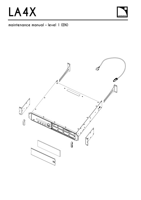
LA4X Arraymaintenance manual – level 1 (EN)ContentsDocument reference: LA4X maintenance manual - level 1 (EN) version 2.0Distribution date: March 20, 2017© L-Acoustics. All rights reserved.No part of this publication may be reproduced or transmitted in any form or by any means without the express written consent of the publisher.ContentsContentsSafety instructions 4 Symbols 4 Revision history 5 Introduction 6 1Equipment and tools 7 2Quality Control 8 3Troubleshooting and diagnosis 10 Diagnosis table (10)Exploded view (16)Working time (16)4Disassembly and Reassembly procedures 17 D/R 001 – REAR BRACKETS (17)D/R 002 – SIDE BRACKETS (18)D/R 003 – GRILL and FOAM FILTER (19)D/R 004 – Power plug (20)D/R 004 bis – FRONT HANDLE (21)Glossary 22 Appendix: KR list 23Safety instructionsSafety instructions1.Strictly follow the sequence of successive steps in all procedures.2.This manual contains the maintenance operations authorized for the end users.Performing another operation exposes to hazardous situations.3.Never incorporate equipment or accessories not approved by L-Acoustics®.4.Do not expose the apparatus to extreme conditions.Do not expose the apparatus to dusty environments, moisture or excessive heat when storing orperforming maintenance procedures.5.Do not store the product on an unstable cart, stand, tripod, bracket, or table.6.Never use a faulty apparatus.An apparatus showing any sign of issue must immediately be put aside and withdrawn from use.7.Contact L-Acoustics for advanced maintenance.Any unauthorized maintenance operation will void the warranty.Before sending a product to L-Acoustics for maintenance, save all user presets to files usingLA Network Manager.SymbolsThe following symbols are used in this document:This symbol indicates a potential risk of harm to an individual or damage to the product.It can also notify the user about instructions that must be strictly followed to ensure safe installation or operation of the product.This symbol indicates a potential risk of electrical injury.It can also notify the user about instructions that must be strictly followed to ensure safe installation or operation of the product.This symbol notifies the user about instructions that must be strictly followed to ensure proper installation or operation of the product.This symbol indicates the equipment, tools, and spare parts required to perform a procedure.This symbol notifies the user about complementary information or optional instructions.Revision historyRevision historyDocument identification Distribution date ModificationsLA4X_MM1_EN_1.0 June 10, 2014 Initial versionLA4X MM1 EN version 2.0 March 20, 2017 - Added D/R 004 bis – FRONT HANDLE- Updated Exploded view- Updated Appendix: KR listIntroductionIntroductionThis manual is intended for end users and gathers the level 1 procedures.This manual contains the maintenance operations authorized for the end users.Performing another operation exposes to hazardous situations.Diagnosis tableThis section contains the diagnosis tables and procedures to identify the issues and how to address them.Exploded viewThis illustration gives an overview of the order in which the elements must be disassembled and reassembled. Each assembly refers to the corresponding module, D/R procedure and inspection procedure (if any).Disassembly and Reassembly proceduresThis section contains the maintenance procedures for each assembly identified in the exploded view.Quality ControlThese checks allow to detect an issue. The quality control must be performed regularly.It is mandatory to perform preventive maintenance actions on a regular basis.Insufficient upkeep of the product can void the warranty.Equipment and tools1Equipment and toolsThe following table is the complete list of equipment and tools required to perform all level 1 maintenance procedures on the LA4X amplified controller.* Refer to the documentation of the electric screwdriver manufacturer to obtain the setting corresponding to a given torque value. This setting can vary depending on the age of the tool. Verify it on a regular basis.Quality Control2Quality ControlThis procedure must be performed for periodic maintenance and to detect possible issues on a controller. ToolsNameaudio source with a known musical programLA NWMCAT5e U/FTP cablefull range loudspeakersubwooferear protectionsProcedureInspect the external structure of the controller for any lost or damaged part.To verify if the controller is clean, follow these steps:a.Disassemble the GRILL and the FOAM FILTER, see procedure D/R 003.b.Verify if the FOAM FILTER is clean.c.Look inside the controller through the front grill (do not touch any part) and verify if the inside is clean.d.Reassemble the GRILL and the FOAM FILTER, see procedure D/R 003.Plug the controller to mains and power it on.Verify if the LCD screen and all LED lit during the start-up sequence.To verify if the network functionalities of the controller work, follow these steps:a.Connect the controller to an Ethernet port of the computer hosting LA NWM.Use the CAT5e U/FTP cable.unch LA NWM.c.Verify if the controller can be put in online mode (refer to the LA NWM video tutorial).Verify if the latest version of firmware is installed (see the LA4X user manual or the LA NWM videotutorial).If not, update firmware from LA NWM.Select a known preset and verify if the indications displayed on screen are in accordance with it.To verify sound presence and quality on each output channel follow these steps:a.Plug the audio source to an input connector of the controller (IN A, IN B, IN C or IN D).b.Plug the full range loudspeaker to output connector OUT1.c.Select a corresponding preset.d.Select the routing from the audio source to OUT1.e.Play the musical program.f.Set the OUT1 gain to -40 dB.g.Unmute OUT1.h.Set the OUT1 gain to obtain a medium sound level.i.Verify if the sound is clear and undistorted.j.Mute OUT1.k.Repeat these steps for OUT2, OUT3 and OUT4.Quality Control There is a risk of ear damage due to high sound level.Use ear protections.To verify the power capability of each output channel follow these steps:a.Plug the audio source to an input connector of the controller (IN A, IN B, IN C or IN D).b.Plug the subwoofer to output connector OUT1.c.Select a corresponding preset.d.Select the routing from the audio source to OUT1.e.Play the musical program.f.Set the OUT1 gain to -40 dB.g.Unmute OUT1.h.Set the OUT1 gain to obtain a high sound level.i.Verify if the sound remains clear and undistorted up to the limit level.j.Mute OUT1.k.Repeat these steps for OUT2, OUT3 and OUT4.Troubleshooting and diagnosis3Troubleshooting and diagnosisDiagnosis tableFor any issue, follow the check sequence in the possible causes column.At each step, apply the inspection procedure (if exists) and consider the resulting diagnosis.Before applying a procedure, consider the EXPLODED VIEW to get acquainted with the disassembly/reassembly procedures to perform before and after.Troubleshooting and diagnosisPOWER CORD notconnected to mainsmains failure or wrongvoltagePOWER CORDdamagedother causecontroller connected to anon-compatible networkcondensing humidity intothe LCD screenother causeTroubleshooting and diagnosisTroubleshooting and diagnosisroom temperature too highFOAM FILTER cloggedcontroller not gettingenough cool airchannel x resourcessolicited to their limitsloudspeaker impedance toolowother causesporadic errorother causesfirmware update failureother causeTroubleshooting and diagnosisFAN blades blockedanythe mains failureoutputs mutedwrong input modewrong preset selectiongain value too low on the controlleraudio source not plugged or plugged into the wrong input connectoraudio source cable incorrectly plugged audio source cable damagedwrong settings on the audio sourcenon-audio bit stream audio source failureloudspeaker not plugged or plugged into the wrong output connector loudspeaker cable incorrectly plugged loudspeaker cable damagedloudspeaker damaged other causesTroubleshooting and diagnosisAES/EBU audio sourceconnected to anANALOG inputgain value too high onthe controlleroutput gain value toohigh on the audio sourceswitch to the analogfallback mode withwrong AES/EBU inputgain valuewrong preset selectionaudio source cableincorrectly pluggedaudio source cabledamagedwrong settings on theaudio sourceaudio source failureloudspeaker pluggedinto the wrong outputconnectorloudspeaker cableincorrectly pluggedloudspeaker cabledamagedloudspeaker damagedother causesTroubleshooting and diagnosisExploded viewThe following exploded view represents the external MODULES of the LA4X. Each MODULE is indicated by a circled number. The orange lines represent the disassembly/reassembly (D/R) order. Refer to the table below for more information.Working timeDisassembly and Reassembly procedures4 Disassembly and Reassembly proceduresD/R 001 – REAR BRACKETS Spare parts KR LABRACKETDisassembly procedureThis procedure describes how to replace the REAR BRACKETS of an LA4X amplified controller. Remove the two REAR BRACKETS pulling on them, see Figure 1.Figure 1: Removing the REAR BRACKETSReassembly procedureThis procedure describes how to mount the REAR BRACKETS kit to an LA4X amplified controller. Insert the two REAR BRACKETS pushing on them until they are locked, see Figure 2.Figure 2: Mounting the REAR BRACKETSDisassembly and Reassembly proceduresD/R 002 – SIDE BRACKETSToolsNameelectric screwdriverTorxSpare partsKR LA4XEQAVDisassembly procedureThis procedure describes how to remove the SIDE BRACKETS from an LA4X amplified controller.Undo the four Torx® screws from the locations indicated in Figure 3.Use the electric screwdriver with the Torx® T10 bit.Figure 3: Removing a SIDE BRACKET Remove the SIDE BRACKET from the controller.Repeat these steps for the other SIDE BRACKET.Reassembly procedureThis procedure describes how to mount a SIDE BRACKETS kit to an LA4X amplified controller.Position a SIDE BRACKET on the controller.Drive four Torx® screws to the locations indicated in Figure 4.Use the electric screwdriver with the Torx® T10 bit. Torque to 1 N.m.Figure 4: Mounting a SIDE BRACKET Repeat these steps with a second SIDE BRACKET on the other side of the controller.Disassembly and Reassembly proceduresD/R 003 – GRILL and FOAM FILTER ToolsName3.5 mm flat screwdriverSpare parts KR LA4XGRI KR LA4XMOU Disassembly procedureThere is a risk of electrical injury and a risk of trapping finger/handBefore any maintenance operation, disconnect the controller from mains and wait for 1 minute so the capacitors discharge completely.This procedure describes how to remove the GRILL and FOAM FILTER from an LA4X amplified controller. Insert the head of the screwdriver in the hole indicated in Figure 5.Figure 5: Removing the GRILLPush the internal latch with the screwdriver and pull out the right side of the GRILL. Push the internal latch with the screwdriver again until the latch comes out of the hole. Remove the GRILL and the FOAM FILTER from the controller.If the FOAM FILTER is intended to be cleaned, use mild dishwashing detergent or soap and then dry it.Reassembly procedureThis procedure describes how to mount a GRILL kit and a FOAM FILTER kit to an LA4X amplified controller. Place a FOAM FILTER into the GRILL.Insert the left side of the GRILL into the controller. Insert the internal latch into the controller. Use the screwdriver.Push on the right side of the GRILL until hearing a click sound.Disassembly and Reassembly proceduresD/R 004 – Power plugToolsNamewire stripping pliersStanley knifescrewdriver adapted to the new powerplugSpare partsSafetyThere is a risk of electrical injury when the high-voltage capacitors are charged.Before the maintenance operation, disconnect the POWER CORD from the mains and from the controller.Replacement procedureThis procedure describes how to replace the power plug on a POWER CORD.Unplug the POWER CORD from the mains.Unplug the POWER CORD from the controller.Cut the POWER CORD near the power plug.Use the Stanley knife.Strip the three wires of the POWER CORD on a length compatible with the new plug.Use the Stanley knife and the wire stripping pliers.Fix the three wires on the new plug according to the color code of Table 1.Use the screwdriver.Table 1: Wire color codeDisassembly and Reassembly proceduresD/R 004 bis – FRONT HANDLEToolsNameelectric screwdriverTorxSpare partsG03255Disassembly procedureThis procedure describes how to remove the FRONT HANDLE from an LA4X amplified controller.1.Undo the two Torx® screws from the locations indicated in Figure 6.Use the electric screwdriver with the Torx® T15 bit.2.Remove the FRONT HANDLE from the controller.3.Repeat these steps for the other FRONT HANDLE.Reassembly procedureThis procedure describes how to mount a FRONT HANDLE to an LA4X amplified controller.FRONT HANDLES can only be mounted on compatible FRONT STRUCTURE.To upgrade a controller with a non-compatible FRONT STRUCTURE, contact your L-Acoustics representative.Self-drilling screwsFor safety reasons, always reassemble new FRONT HANDLES.1.Position a FRONT HANDLE on the controller.2.Drive two Torx® screws to the locations indicated in Figure 6.Use the electric screwdriver with the Torx® T15 bit. Torque to 1 N.m3.Repeat these steps for the other FRONT HANDLE.Figure 6: Mounting a FRONT HANDLEGlossaryGlossaryCE EuropeCN ChinaD/R disassembly/reassemblyKR Replacement KitLA NWM La Network Manager remote control softwareMODULE part of an amplified controller, written in uppercase characters N.m newton meter, international torque unit, 1 N.m = 9 in.lb fUS United StatesAppendix: KR list Appendix: KR listL-Acoustics, an L-Group Company13 rue Levacher Cintrat – 91460 Marcoussis – France+33 1 69 63 69 63 –********************L-Acoustics GmbH Steiermärker Str. 3-5 70469 StuttgartGermany+49 7 11 89660 323L-Acoustics Ltd.PO. Box Adler Shine - Aston HouseCornwall Avenue - London N3 1LFUnited Kingdom+44 7224 11 234L-Acoustics Inc.2645 Townsgate Road, Suite 600Westlake Village, CA 91361USA+1 805 604 0577。
电脑主板维修辅助工具使用说明

电脑主板维修辅助工具使用说明一、工具介绍1.万用表:用于检测电压、电流和电阻值等电学参数。
2.烙铁:用于焊接和烙接电路元件。
3.风扇:用于测试主板通电后的风扇转速。
4.主板电源:用于检测主板的供电情况。
5.PCIE检测卡:用于检测主板上的PCI-E插槽是否正常。
6.BIOS编程器:用于刷写主板上的BIOS。
7.CMOS电池:用于更换主板上的备份电池。
B转串口线:用于连接主板和电脑,提供串口通信功能。
9.芯片针座:用于测试主板上的芯片。
10.隔热胶带:用于防止电路板上的元件短路。
以上是主要的工具和设备,根据不同的故障情况,可能需要额外的仪器和工具。
二、使用步骤1.首先,关闭电脑并拔掉电源插头,确保安全。
2.打开电脑主机箱,将主板取出。
3.用万用表检测主板的供电情况,检查主板上的电源插座和电源相关元件。
如果发现电源不通电,可以使用主板电源进行检测,确定电源是否故障。
4.使用烙铁对主板上的元件进行焊接和烙接,确保连接良好。
5.将风扇插到主板上,通电后检查风扇转速是否正常。
6.使用PCIE检测卡插入PCI-E插槽,检测插槽是否正常。
7.如果主板无法正常启动,可以尝试使用BIOS编程器刷写主板上的BIOS。
8.如果主板时间不准,可能是CMOS电池电量不足,可以使用CMOS电池进行更换。
9.如果需要跟主板进行串口通信,可以使用USB转串口线进行连接。
10.如果需要测试主板上的芯片,可以使用芯片针座进行接触测试。
11.使用隔热胶带在电路板上需要保护的区域进行覆盖,防止短路。
12.在维修完成后,将主板重新安装回电脑主机箱,关闭主机箱。
三、注意事项1.在进行维修操作之前,确认自己有一定的电脑维修技能和经验,避免造成更大的损坏。
2.在进行维修操作之前,务必断开电源并等待电容放电,避免触电和烧坏主板。
3.在使用烙铁时,注意使用适当的温度和电镀,以免烧坏主板上的元件。
4.在使用PCIE检测卡时,小心插拔,避免损坏插槽。
NVIDIA DOCA Tools MLNX-15-060529 _v2.0.2 使用说明书

OverviewTable of ContentsChapter 1. Introduction (1)Chapter 2. DOCA Tools (2)2.1. Comm Channel Admin Tool (2)2.2. DPA HART Management Tool (2)2.3. DPACC Compiler (2)2.4. DPI Compiler (2)2.5. FlexIO Build (3)2.6. RXP Compiler (3)2.7. RXPBench (3)2.8. Socket Relay (3)Chapter 1.IntroductionDOCA tools are a set of executables/scripts that are needed to produce inputs to some of the DOCA libraries and applications.All tools are installed with DOCA, as part of the doca-tools package, and can either be directly accessed from the terminal or can be found at /opt/mellanox/doca/tools. Refer to NVIDIA DOCA Installation Guide for Linux for more information.List of tools for both the host and the NVIDIA® BlueField® DPU:‣DPI compiler‣RXP compiler (rxpc)‣RXPBenchChapter 2.DOCA Tools2.1. Comm Channel Admin ToolCLI name: doca_comm_channel_admin_toolThe Comm Channel Admin Tool is used to monitor Comm Channel services and connections on both the DPU and the host.2.2. DPA HART Management ToolCLI name: dpahartmgmtThe DPA HART management tool allows users to manage the DPA's HARTs which are the basic resource of the DPA. The tool enables the resource control of HARTs to optimize the usage of computation resources of the DPA. Using this tool, users may query, create, and destroy HART partitions and groups, thus ensuring proper HART allocation between devices.2.3. DPACC CompilerCLI name: dpaccDPACC is a high-level compiler for the DPA processor. It compiles code targeted for the DPA processor into an executable and generates a DPA program.The DPA program is a host library with interfaces encapsulating the DPA executable. This DPA program can be linked with the host application to generate a host executable where the DPA code is invoked through the FlexIO runtime API.2.4. DPI CompilerCLI name: doca_dpi_compilerThis tool is used to create one of the necessary inputs to the DOCA DPI library.DOCA ToolsThe DPI compiler is used to compile a signature file which is loaded into the BlueField RegEx HW accelerator using a dedicated API (doca_dpi_load_signatures(cdo_file)). The output for the DPI compiler is a JSON-based CDO file.2.5. FlexIO BuildCLI name: build_flexio_deviceThe FlexIO Build tool is used to build and compile FlexIO device code into a static library. It is designed to generate a host library that encapsulating DPA execution. This tool relies on DPACC.2.6. RXP CompilerCLI name: rxpcThis tool is used to generate a ROF file that can be used by a customer application to program the NVIDIA® RXP® accelerator rules memories.The RXP compiler is used to compile RegExes into RXP Object Format (ROF) to be executed on the RXP accelerator.The DOCA RegEx library can be used to load the binary ROF file into the RXP.2.7. RXPBenchCLI name: rxpbenchRXPBench is a tool that allows performance comparison between the NVIDIA® RXP®hardware RegEx acceleration engine, found in the NVIDIA® BlueField® DPU, and the Intel®Hyperscan software library. It provides a comprehensive set of options and facilitates ingress of data from live network ports or previously recorded PCAP files.It is designed to provide a real-world comparison of these technologies and present the results customers could expect to receive after implementing either technology in their products.2.8. Socket RelayCLI name: doca_socket_relayDOCA Socket Relay allows Unix Domain Socket (AF_UNIX family) server applications to be offloaded to the DPU while communication between the two sides is proxied by DOCA Comm Channel.NoticeThis document is provided for information purposes only and shall not be regarded as a warranty of a certain functionality, condition, or quality of a product. NVIDIA Corporation nor any of its direct or indirect subsidiaries and affiliates (collectively: “NVIDIA”) make no representations or warranties, expressed or implied, as to the accuracy or completeness of the information contained in this document and assume no responsibility for any errors contained herein. NVIDIA shall have no liability for the consequences or use of such information or for any infringement of patents or other rights of third parties that may result from its use. This document is not a commitment to develop, release, or deliver any Material (defined below), code, or functionality.NVIDIA reserves the right to make corrections, modifications, enhancements, improvements, and any other changes to this document, at any time without notice.Customer should obtain the latest relevant information before placing orders and should verify that such information is current and complete.NVIDIA products are sold subject to the NVIDIA standard terms and conditions of sale supplied at the time of order acknowledgement, unless otherwise agreed in an individual sales agreement signed by authorized representatives of NVIDIA and customer (“Terms of Sale”). NVIDIA hereby expressly objects to applying any customer general terms and conditions with regards to the purchase of the NVIDIA product referenced in this document. No contractual obligations are formed either directly or indirectly by this document.NVIDIA products are not designed, authorized, or warranted to be suitable for use in medical, military, aircraft, space, or life support equipment, nor in applications where failure or malfunction of the NVIDIA product can reasonably be expected to result in personal injury, death, or property or environmental damage. NVIDIA accepts no liability for inclusion and/or use of NVIDIA products in such equipment or applications and therefore such inclusion and/or use is at customer’s own risk.NVIDIA makes no representation or warranty that products based on this document will be suitable for any specified use. Testing of all parameters of each product is not necessarily performed by NVIDIA. It is customer’s sole responsibility to evaluate and determine the applicability of any information contained in this document, ensure the product is suitable and fit for the application planned by customer, and perform the necessary testing for the application in order to avoid a default of the application or the product. Weaknesses in customer’s product designs may affect the quality and reliability of the NVIDIA product and may result in additional or different conditions and/or requirements beyond those contained in this document. NVIDIA accepts no liability related to any default, damage, costs, or problem which may be based on or attributable to: (i) the use of the NVIDIA product in any manner that is contrary to this document or (ii) customer product designs.No license, either expressed or implied, is granted under any NVIDIA patent right, copyright, or other NVIDIA intellectual property right under this document. Information published by NVIDIA regarding third-party products or services does not constitute a license from NVIDIA to use such products or services or a warranty or endorsement thereof. Use of such information may require a license from a third party under the patents or other intellectual property rights of the third party, or a license from NVIDIA under the patents or other intellectual property rights of NVIDIA.Reproduction of information in this document is permissible only if approved in advance by NVIDIA in writing, reproduced without alteration and in full compliance with all applicable export laws and regulations, and accompanied by all associated conditions, limitations, and notices.THIS DOCUMENT AND ALL NVIDIA DESIGN SPECIFICATIONS, REFERENCE BOARDS, FILES, DRAWINGS, DIAGNOSTICS, LISTS, AND OTHER DOCUMENTS (TOGETHER AND SEPARATELY, “MATERIALS”) ARE BEING PROVIDED “AS IS.” NVIDIA MAKES NO WARRANTIES, EXPRESSED, IMPLIED, STATUTORY, OR OTHERWISE WITH RESPECT TO THE MATERIALS, AND EXPRESSLY DISCLAIMS ALL IMPLIED WARRANTIES OF NONINFRINGEMENT, MERCHANTABILITY, AND FITNESS FOR A PARTICULAR PURPOSE. TO THE EXTENT NOT PROHIBITED BY LAW, IN NO EVENT WILL NVIDIA BE LIABLE FOR ANY DAMAGES, INCLUDING WITHOUT LIMITATION ANY DIRECT, INDIRECT, SPECIAL, INCIDENTAL, PUNITIVE, OR CONSEQUENTIAL DAMAGES, HOWEVER CAUSED AND REGARDLESS OF THE THEORY OF LIABILITY, ARISING OUT OF ANY USE OF THIS DOCUMENT, EVEN IF NVIDIA HAS BEEN ADVISED OF THE POSSIBILITY OF SUCH DAMAGES. Notwithstanding any damages that customer might incur for any reason whatsoever, NVIDIA’s aggregate and cumulative liability towards customer for the products described herein shall be limited in accordance with the Terms of Sale for the product.TrademarksNVIDIA, the NVIDIA logo, and Mellanox are trademarks and/or registered trademarks of Mellanox Technologies Ltd. and/or NVIDIA Corporation in the U.S. and in other countries. The registered trademark Linux® is used pursuant to a sublicense from the Linux Foundation, the exclusive licensee of Linus Torvalds, owner of the mark on a world¬wide basis. Other company and product names may be trademarks of the respective companies with which they are associated.Copyright© 2023 NVIDIA Corporation & affiliates. All rights reserved.NVIDIA Corporation | 2788 San Tomas Expressway, Santa Clara, CA 95051。
Pepperl+Fuchs 14 KFD2-EB2.R4A.B 重复电源模块说明书
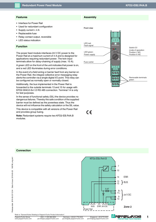
16-05-23 12:04D a t e o f i s s u e 2016-05-23189784_e n g .x m l14131571024 V DC9-12-8+11+BUSERR ConnectionAssembly•Interface for Power Rail•Used for redundant configuration •Supply current ≤ 4 A •Replaceable fuse•Relay contact output, reversible •LED status indicationFunctionThe power feed module interfaces 24V DC power to the Power Rail at a maximum current of 4A and is designed for applications requiring redundant power. The twin input terminals allow for daisy-chaining of supply (max. 10A).A green LED on the front of the unit indicates that power is on, and a red LED illuminates during error conditions.In the event of a field wiring or barrier fault from any barrier on the Power Rail, the integral collective error messaging relay alerts the controller via a single digital I/O point. This relay can be configured as normally open or normally closed.Additionally, the bus implemented in the Power Rail isforwarded to the outside terminals 13 and 15 for usage with KFD2-WAC2-Ex1.D RS 485 connection. Terminal 14 is only for test purposes.In the sense of functional safety (SIL) the device provides no dangerous failures. Thereby the safe condition of the supplied barrier must be defined as the powerless state. Thus the device will not influence the safety calculation or the SIL value.This device is compatible with all versions of the Power Rail and provides group fusing.Note: Redundant systems require two KFD2-EB.R4A.B modules.FeaturesFront view16-05-23 12:04D a t e o f i s s u e 2016-05-23189784_e n g .x mlSupplyConnection terminals 11+, 12-terminals 8+, 9-Rated voltage U n20 ... 30 V DCThe maximum rated operating voltage of the devices plugged onto the Power Rail must not be exceeded.Power dissipation ≤ 2.4 WOutputSupply Output current: ≤ 4 A Fault signal relay output: NO contactContact loading30 V AC/ 2 A / cos φ ≥ 0.7 ; 40 V DC/ 2 A Energized/De-energized delay approx. 20 ms / approx. 20 msFuse rating5 Arecommended maximum utilization of the fuse: 80 %Directive conformity Electromagnetic compatibilityDirective 2014/30/EU EN 61326-1:2013 (industrial locations)ConformityElectromagnetic compatibility NE 21:2006Degree of protection IEC 60529:2001Ambient conditions Ambient temperature -20 ... 60 °C (-4 ... 140 °F)Mechanical specifications Degree of protection IP20Mass approx. 100 gDimensions 20 x 119 x 115 mm (0.8 x 4.7 x 4.5 in) , housing type B2Mountingon 35 mm DIN mounting rail acc. to EN 60715:2001Data for application in connection with Ex-areasStatement of conformityTÜV 00 ATEX 1618 X Group, category, type of protection, temperature class ¬ II 3G Ex nA nC IIC T4Directive conformityDirective 2014/34/EU EN 60079-0:2012+A11:2013 , EN 60079-15:2010International approvals FM approval Control drawing 116-0160Approved for Class I, Division 2, Groups A, B, C, D; Class I, Zone 2, IIC UL approvalApproved for Class I, Division 2, Groups A, B, C, D; Class I, Zone 2, IIC CSA approval Control drawing 116-0160Approved for Class I, Division 2, Groups A, B, C, D; Class I, Zone 2, IIC IECEx approval IECEx UL 16.0051Approved for Ex nA nC IIC T4 Gc General information Supplementary informationStatement of Conformity, Declaration of Conformity, Attestation of Conformity and instructions have to be observed where applicable. For information see .16-05-23 12:04D a t e o f i s s u e 2016-05-23189784_e n g .x mlPower feed module KFD2-EB2The power feed module is used to supply the devices with 24 V DC via the Power Rail. The fuse-protected power feed module can supply up to 150individual devices depending on the power consumption of the devices. Collective error messages received from the Power Rail activate a galvanically-isolated mechanical contact.Power Rail UPR-03The Power Rail UPR-03 is a complete unit consisting of the electrical insert and an aluminium profile rail 35mm x 15mm. To make electrical contact, the devices are simply engaged.Profile Rail K-DUCT with Power RailThe profile rail K-DUCT is an aluminum profile rail with Power Rail insert and two integral cable ducts for system and field cables. Due to this assembly no additional cable guides are necessary.Power Rail and Profile Rail must not be fed via the device terminals of the individual devices!Accessories。
《多媒体技术与应用》按章复习题
《多媒体技术应用》复习题第1章多媒体技术概述一、单选题1、媒体有两种含义:即表示信息的载体和( B )。
A.表达信息的实体 B.存储信息的实体C.传输信息的实体 D.显示信息的实体2、( A )是指用户接触信息的感觉形式,如视觉、听觉、触觉、嗅觉和味觉等。
A.感觉媒体 B.表示媒体 C.表现媒体 D.传输媒体3、( C )是表现和获取信息的物理设备,如键盘、鼠标器和显示器等。
A.感觉媒体 B.表示媒体 C.表现媒体 D.传输媒体4、( B )是用于处理文本、音频、图形、图像、动画和视频等计算机编码的媒体。
A.感觉媒体 B.表示媒体 C.显示媒体 D.传输媒体5、在多媒体计算机中,静态媒体是指( B ) 。
A.音频B.图像C.动画D.视频6、人类听觉可以从外部世界获取( C )左右的信息。
A.80% B.20% C.10% D.5% 7、人类视觉可以从外部世界获取( A )左右的信息。
A.80% B.20% C.10% D.5%8、在多媒体课件中,课件能够根据用户答题情况给予正确和错误的回复,突出显示了多媒体技术的( D )。
A.多样性B.非线性 C.集成性D.交互性9、计算机主机与显示器之间的接口电路是( C )。
A.网卡 B.音频卡 C.显示卡 D.视频压缩卡10、计算机主机与音箱之间的接口电路是( B )。
A.显示卡 B.音频卡 C.压缩卡 D.网卡11、( D )是一种记录声音和活动图像的视频设备。
A.扫描仪 B.数码相机 C.投影仪 D.数字摄像机12、 ( A )不能用于网上传送实时影像。
A.数码相机 B.计算机摄像机 C.数字摄像头 D.网络摄像机13、多媒体软件可分为( C )。
A.多媒体系统软件、多媒体应用软件B.多媒体系统软件、多媒体操作系统、多媒体编言C.多媒体系统软件、多媒体支持软件、多媒体应用软件D.多媒体操作系统、多媒体支持软件、多媒体著作工具14、多媒体系统的层次结构中,( D )是直接用来控制和管理多媒体硬件,并完成设备的各种操作。
MD214L可编程文本显示器使用手册中文版

目录第一章产品概述 (1)1.1功能 (1)1.2一般规格 (1)1.3各部分名称 (2)1.4外型尺寸及安装方法 (4)第二章编辑软件TP200 (5)2.1 TP200基本概述 (5)2.2编辑用户画面 (5)2.3保存工程 (29)2.4下载画面 (30)2.5 导入旧工程 (30)第三章操作方法 (32)3.1联机通讯 (32)3.2切换画面 (32)3.3系统口令 (32)3.4修改数据 (33)3.5开关量控制 (34)第四章与PLC的连接方法 (35)4.1三菱FX系列 (35)4.2西门子S7-200系列 (36)4.3欧姆龙C系列 (36)4.4施耐德NEZA/TWIDO系列 (37)4.5 台达DVP系列 (38)4.6松下FP系列 (38)4.7 LG Master-K CNet系列 (39)4.8 LG系列 Modbus 协议 (40)4.9 LG Master-K 120S 编程口通讯 (41)4.10 FACON永宏系列 (41)4. 11 光洋S系列 (42)4.12 ECOSTEP 系列 (43)4.13 AB Micrologix系列 (44)4.14 MODBUS RTU/ASCII/EMERSON/RTU EXTEND (45)4.15 MODBUS SERVER (46)4.16 eView自由协议 (47)4.17 SAIA PCD S-BUS协议 (48)4.18 VIGOR PLC (49)4.19 EMERSON EC20系列PLC (49)4.20 KEYENCE KV系列PLC (50)eView TP200 V4.7.0 组态软件Release Note (51)附录1:自由协议文档 (56)附录2:其它注意事项 (58)第一章产品概述1.1功能MD214L是一个小型的人机界面,主要与各类PLC(或带通信口的智能控制器)配合使用,以文字或指示灯等形式监视、修改PLC内部寄存器或继电器的数值及状态,从而使操作人员能够自如地控制机器设备。
联想Lenovo ThinkBook 14 Gen 2和ThinkBook 15 Gen 2用户指南

用户指南Lenovo ThinkBook14Gen2和Lenovo ThinkBook15Gen2用前必读使用本文档及其支持的产品之前,请务必先阅读和了解以下信息:•第29页附录A“重要安全信息”•《安全与保修指南》•《设置指南》第一版(2021年7月)©Copyright Lenovo2021.有限权利声明:如果数据或软件依照美国总务署(GSA)合同提供,其使用、复制或公开受编号为GS-35F-05925的合同的条款的约束。
目录关于本指南 (iii)第1章了解计算机 (1)前视图 (1)底座视图 (2)左视图 (4)右视图 (6)底视图 (8)功能部件和规格 (9)USB传输速率声明 (11)运行环境 (11)第2章开始使用您的计算机 (13)使用Windows (13)Windows帮助信息 (13)Lenovo Vantage和联想电脑管家 (14)Novo按钮菜单 (14)打开Novo按钮菜单 (14)与计算机交互 (14)键盘热键 (14)数字小键盘 (16)使用多点触控式屏幕 (16)第3章了解您的计算机 (19)管理电源 (19)检查电池状态 (19)为电池充电 (19)设置电源按钮行为 (19)更改或创建电源计划 (19)设置性能模式 (19)更改UEFI/BIOS Setup Utility中的设置..20 UEFI/BIOS Setup Utility是什么 (20)打开UEFI/BIOS Setup Utility (20)选择引导设备 (20)更改热键模式 (20)启用或禁用Always-on (20)启用或禁用Flip to Boot (21)在UEFI/BIOS Setup Utility中设置密码..21密码类型 (21)设置管理员密码 (21)更改或删除管理员密码 (22)设置用户密码 (22)启用开机密码 (22)设置硬盘密码 (22)更改或删除硬盘密码 (23)第4章帮助和支持 (25)常见问题 (25)自助资源 (25)CRU是什么? (26)您的产品型号适用的CRU (26)致电Lenovo (27)联系Lenovo之前 (27)Lenovo客户支持中心 (27)购买附加服务 (28)附录A重要安全信息 (29)附录B辅助功能和人体工程学信息 (39)附录C合规性信息 (41)附录D声明和商标 (55)©Copyright Lenovo2021iii用户指南关于本指南•本指南适用于下面列出的Lenovo产品型号。
- 1、下载文档前请自行甄别文档内容的完整性,平台不提供额外的编辑、内容补充、找答案等附加服务。
- 2、"仅部分预览"的文档,不可在线预览部分如存在完整性等问题,可反馈申请退款(可完整预览的文档不适用该条件!)。
- 3、如文档侵犯您的权益,请联系客服反馈,我们会尽快为您处理(人工客服工作时间:9:00-18:30)。
画和按钮等对象。
各对象可按层次结构来组织。
多媒体技术:多媒体编著工具
陈科文主讲
4.3 Tool Book 操作环境
Tool Book 环境 Tool Book应用 程序窗口由 “标题栏、 菜单栏、 工具栏、 书页/背景、 工具板和 状态栏”组成。
菜单栏
工具栏
书页/背景
工具板 状态栏
多媒体技术:多媒体编著工具
陈科文主讲
4.3.1 Tool Book 对象层次
Tool Book的内部组织
结构称为对象层次。 在对象层次中,对象 按顺序排列,如字段、 按钮和图形、组、页、 背景、书、系统书。 Tool Book中任何包含 对象的组、页、背景 或书都称为该对象的 父元素。
ToolBook书 页系Fra bibliotek书 图形 背景
《多媒体技术》课程
四、多媒体编著工具 ToolBook
中南大学 信息科学与工程学院
4.1 Tool Book 概述
ToolBook 是一种面向对象的多媒体开发工
具,由美国Asymetrix公司推出。适用于创 作功能丰富的多媒体课件和多媒体读物。 ToolBook设计过程如同构造一本书。首先 建立一本书的整体框架,接着可在书中添 加页,再把文字、图像、按钮等对象放入 页中。 应用系统的建立主要通过使用程序设计语 言 OpenScript 来编写脚本,确定各种对象 在课件中的作用。
多媒体技术:多媒体编著工具
陈科文主讲
4.1 Tool Book 概述
ToolBook
4.0 以上 的版本增加了强大 的课件开发工具集 和课程管理系统; ToolBookⅡ提供了 在Internet网络环境 下进行分布式系统 的解决方案。
4.2 ToolBook 的制作工程
1. 首先建立一本书的整体框架。 2. 在书中添加页。 3. 再在页中加入背景、文字、图像、动
多媒体技术:多媒体编著工具
陈科文主讲
4.1 Tool Book 概述
Tool Book的功能和特点 采用通用用户界面,具有文本、绘图、声音、 动画和影片编辑功能。所不同的是它的可视化 内容分为作者层和读者层; Tool Book采用传统图书的特性,以页为单位,, 多个页按顺序或通过超链接组合成一个完整的 作品; 把超文本和数据库功能加入多媒体应用中; 采用面向对象的多媒体开发环境,提供一种容 易使用的Open Script 描述语言; 易用、方便、功能丰富,减少了建立专业课件 所用的时间;
陈科文主讲
4.3.3 Tool Book 的应用层次
作 者 层 中 的 工 具
选择工具 按钮工具 放大工具
选择区域工具
组合框工具 OLE容器工具
绘图工具
舞台工具
多媒体技术:多媒体编著工具
陈科文主讲
4.3.3 Tool Book 的应用层次
2. 处于读者层次时,可以执行或播出这个
多媒体节目,即可以让读者阅读这本书, 此时菜单条上只有五项菜单,也没有工 具箱。所以读者不能编辑这本书,只能 阅读。 开发者在作者层建立应用,在读者层测 试执行应用,最终用户在读者层执行应 用。
多媒体技术:多媒体编著工具
陈科文主讲
4.4 Tool Book 的程序设计
脚本语言: 通过使用ToolBook的 程 序 语 言 OpenScript 可以为每一个对象编 写脚本,由此来决定 应用程序怎样为对象 的特定消息作出反应。
多媒体技术:多媒体编著工具
陈科文主讲
描述语言
多媒体技术:多媒体编著工具
陈科文主讲
4.3.2 Tool Book 中的“书”
用Tool Book建立
字段 页
的文件称为书 ( Book ),文件 图形对象 扩展名为.TBK。 书的组成还包括: 图形、字段、视 图、书页、按钮 和背景等,
视图 按钮 背景
多媒体技术:多媒体编著工具
陈科文主讲
4.3.3 Tool Book 的应用层次
启 动 Tool Book
后,可以有两 种应用层次供 选择:
作者层次, 读者层次。
多媒体技术:多媒体编著工具
陈科文主讲
4.3.3 Tool Book 的应用层次
1.
作者层:提供了很多工具和命令可以用来建 立或修改对象。处于作者层次的菜单条上有 八项菜单,并且在左侧有一个工具箱。 工具板的主要作用是提供给作者在创作时所 要使用的工具,如绘图、编写文字、放大镜、 选择工具、按钮工具、字段工具、对象绘制 工具、角线工具、矩形工具、不规则多边形 工具等等。 在作者层次不能直接执行或播出节目。 多媒体技术:多媒体编著工具