S2524G智能以太网交换机使用说明书
HR-SWG20244S 28 口千兆管理型以太网交换机说明书

HR-SWG20244S28口千兆管理型以太网交换机【产品概述】HR-SWG20244S是28口千兆管理型以太网交换机,提供24个千兆下联网口+4个千兆上联SFP光口+1个Console口;交换容量高达192Gbps;二层网络管理功能,支持路由、DHCP、VLAN、MAC地址、ACL访问控制、QoS、组播、风暴抑制、IPV4/IPV6等业务功能;支持环网,极速检测及自愈功能;支持802.1X认证、ARP入侵检测、IP源防护、DoS防护等安全控制策略;支持STP/RSTP/MSTP生成树协议、动/静态链路汇聚等网络保护功能;支持Web/Telnet/CLI/SSH等多种管理维护方式;采用黑色铁质外壳设计;DC12V电源接入;面板上有LED指示灯,可以动态显示设备连接和运行,提供简单的故障检测方法,轻巧简便;主要应用于工业园区、楼宇、厂矿、政府机关、社区等用户网络的以太网接入/汇聚层。
【主要特点】支持24个千兆下联网口+4个千兆上联SFP光口+1个管理端口符合IEEE802.3、IEEE802.3u、IEEE802.3ab、IEEE802.3z标准存储转发交换机制,整机交换容量高达192Gbps二层网络管理,支持路由/DHCP/VLAN/MAC地址/ACL/QoS等业务功能支持环网功能,极速检测及自愈功能支持802.1X认证、ARP入侵检测、IP源防护、DoS防护等安全控制策略支持STP/RSTP/MSTP生成树协议、动/静态链路汇聚等网络保护功能支持WEB、TELNET、CLI、SSH、SNMP网络维护管理方式【应用环境】城域光纤宽带网:电信、有线电视、网络系统集成等数,据网络运营商宽带专网:适用于金融、政府、石油、铁路、电力、公安、交通、教育等行业专网多媒体传输:图像、话音、数据综合传输、适用于远程教学、会议电视、可视电话等应用 实时监控:实时控制信号、图像及数据同时传输【技术指标】【订购信息】【产品效果图】。
NETGEAR 智能交换机安装指南说明书
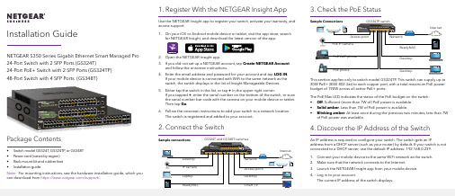
1. Register With the NETGEAR Insight AppUse the NETGEAR Insight app to register your switch, activate your warranty, and access support.1. On your iOS or Android mobile device or tablet, visit the app store, searchfor NETGEAR Insight, and download the latest version of the app.2. Open the NETGEAR Insight app.3. If you did not set up a NETGEAR account, tap Create NETGEAR Accountand follow the onscreen instructions.4. Enter the email address and password for your account and tap LOG IN .24-Port Switch with 2 SFP Ports (GS324T)24-Port PoE+ Switch with 2 SFP Ports (GS324TP) 3. Check the PoE StatusNETGEAR, Inc.350 East Plumeria DriveSan Jose, CA 95134, USA NETGEAR INTL LTDBuilding 3, University Technology Centre Curraheen Road, Cork, Ireland© NETGEAR, Inc., NETGEAR and the NETGEAR Logo are trademarks of NETGEAR, Inc. Any non‑NETGEAR trademarks are used for reference purposes only.SupportThank you for purchasing this NETGEAR product. You can visithttps:///support/ to register your product, get help, access the latest downloads and user manuals, and join our community. We recommend that you use only official NETGEAR support resources.Si ce produit est vendu au Canada, vous pouvez accéder à ce document en français canadien à https:///support/download/.(If this product is sold in Canada, you can access this document in Canadian French at https:///support/download/.)For regulatory compliance information including the EU Declaration of Conformity, visit https:///about/regulatory/.See the regulatory compliance document before connecting the power supply.Do not use this device outdoors. If you connect cables or devices that are outdoors to this device, see https:///000057103 for safety and warranty information.November 20185. Configure the SwitchWe recommend that you use a web browser on a computer or tablet to configure the switch.Note: If your computer is a Mac, use the NETGEAR Switch Discovery Tool, as described in the following section.1. Open a web browser from a computer or tablet connected to the samenetwork as your switch.You can use a WiFi or wired connection. 2. Enter the IP address of the switch.3. Enter the password.The default password is password . We recommend that you change the password to a more secure password.4. Click the Login button.Other Discovery and Configuration MethodsThe NETGEAR Switch Discovery Tool and the Smart Control Center Utility let you discover the IP address and configure the switch. •NETGEAR Switch Discovery Tool . You can use a Mac or a 64-bit Windows-based computer that is on the same network as the switch. You can use a WiFi or wired connection. When you discover the switch, this tool provides access to the local browser interface to c onfigure the switch. To download the NETGEAR Switch Discovery Tool, visit/support/product/netgear-switch-discovery-tool.aspx .•Smart Control Center Utility . You can use a Windows-based computer that is on the same network as the switch. This utility requires Adobe Air. If Adobe Air is not detected during Smart Control Center Utility installation, you are prompted to allow Adobe Air to be installed. To download this utility, visit /support/product/SCC .Note: If you cannot discover or configure the switch, you might need totemporarily disable the firewall, Internet security, or antivirus programs. Make sure to reenable these security services after you discover and configure the switch.PoE ConsiderationsThe PoE and PoE+ power supplied by the GS324TP switch is prioritized inascending port order (from port 1 to port 24), with a total power budget of 190 watts. If the power requirements for the attached powered devices (PDs) exceed the total power budget of the switch, the PD on the highest-numbered port is disabled to make sure that the PDs that are connected to the higher-priority, lower-numbered ports are supported first.The following table describes the PoE classes and switch allocations.Device ClassStandard ClassDescriptionPowerReserved by the DevicePower Delivered to the Device*0PoE and PoE+Default power (full)15.4W 0.44W–12.95W 1PoE and PoE+Very low power 4.0W 0.44W–3.84W 2PoE and PoE+Low power 7.0W 3.84W–6.49W 3PoE and PoE+Mid power 15.4W 6.49W–12.95W 4PoE+ onlyHigh power30.0W12.95W–25.5W* Calculated with the maximum cable length of 328 feet (100 meters). Shorter cable lengths will provide power closer to the power reserved by the switch.。
S2524G智能以太网交换机使用手册

使用手册S2524G智能以太网交换机声明Copyright © 2009-2010 深圳市龙维科技股份有限公司及其许可者版权所有,保留一切权利。
未经龙维公司书面许可,任何单位和个人不得擅自摘抄、复制本书内容的部分或全部,并不得以任何形式传播。
为深圳市龙维科技股份有限公司的注册商标,对于本手册中出现的其它公司的商标、产品标识及商品名称,由各自由权利人拥有。
由于产品版本升级或其它原因,本手册内容有可能变更。
龙维公司保留在没有任何通知或者提示的情况下对本手册的内容进行修改的权利。
本手册仅作为产品使用指导,龙维公司尽全力在本手册中提供准确的信息,但是并不确保手册内容完全没有错误,本手册中的所有陈述、信息和建议也不构成任何明示或暗示的担保。
相关手册手册名称用途ECOM S2524G智能以太网交换机使用手册详细地介绍用户如何通过WEB界面对ECOM S2524G智能以太网交换机进行配置和管理ECOM 10/100/1000M智能以太网交换机快速入门详细地介绍ECOM S2524GF智能以太网交换机的硬件特性及安装过程在本手册中所提到的交换机如无特别说明系指ECOM S2524G,简称为S2524G。
本说明手册中的图片都配有相关参数,这些参数和图片主要为您正确使用该产品提供参考。
在产品实际应用时,需要结合实际需要来配置。
技术支持用户支持邮箱:service@技术支持热线:4008-828-018网址:目录第一章产品简介 (6)1.1产品概述 (6)1.2产品特性 (6)1.3产品规格 (6)第二章配置准备 (9)2.1基本配置要求 (9)2.1.1用户计算机要求 (9)2.1.2建立正确的网络设置 (10)2.2配置入门 (10)2.2.1连接设置 (10)2.2.2测试计算机与交换机是否连通 (11)第三章通过WEB页面配置 (12)3.1登录WEB网管 (12)3.1.1 配置页面介绍 (12)3.1.2 菜单简介 (12)3.1.3 常用按钮介绍 (15)3.2配置信息 (15)3.2.1系统配置 (15)3.2.2端口配置 (16)3.2.3 VLAN 配置 (17)3.2.4汇聚配置 (23)3.2.5LACP 配置 (23)3.2.6 RSTP 配置 (24)3.2.7 802.1X 配置 (25)3.2.8 IGMP 配置 (26)3.2.9 镜像配置 (28)3.2.10 QOS 配置 (29)3.2.11 安全配置 (32)3.2.12 速率配置 (32)3.2.13 广播风暴控制 (33)3.3 状态信息 (34)3.3.1 端口统计 (34)3.3.2 端口信息 (34)3.3.3 LACP状态 (35)3.3.4 RSTP 状态 (35)3.3.5 IGMP 状态 (36)3.3.6 VeriPHY (36)3.3.7 Ping 配置 (37)3.4 管理设备 (38)3.4.1重启设备 (38)3.4.2恢复出厂配置 (38)3.4.3软件升级 (38)3.4.4备份/恢复 (38)3.4.5 退出 (39)第四章维护与常见故障处理 (42)4.1 S2524GF如何升级软件 (46)4.2电源系统故障 (46)4.3端口不能正常通信 (47)前言手册说明本文档用于指导您如何正确配置本产品。
S2526F智能以太网交换机使用说明书

3.3.3 带宽控制............................................................................................................ 16 3.4 VLAN 设置............................................................................................................... 17
第三章 WEB 界面设置.............................................................................................................. 10 3.1 菜单简介...................................................................................................................10 3.2 系统管理...................................................................................................................12 3.2.1 管理者设置........................................................................................................ 12 3.2.2 IP 设置.............................................................................................................. 12 3.2.3 系统状态............................................................................................................ 13 3.2.4 恢复默认设置.....................................................................................................13 3.2.5 软件升级............................................................................................................ 13 3.2.6 重启设备............................................................................................................ 14 3.3 端口管理...................................................................................................................14 3.3.1 端口设置............................................................................................................ 14 3.3.2 端口镜像............................................................................................................ 15
友讯PS2024G 24端口千兆三层POE交换机使用说明书

User manualPS2024G24Port Gigabit Layer3PoE SwitchInstallation manual introductionThe Product installation manual mainly describes PS2024GPoE switch hardware features,installation methods,and precautions during the installationThis manual includes the following chapters:Chapter1:Product Introduction.Briefly describes the basic features,Detailed hardware&software specifications of the switch and the appearance details.Chapter2:Product Installation.Guide the switch hardware installation methods and precautions.Chapter3:Hardware Connections.Guide the connection between switches and other devices and precautions.Chapter4:Packaging and product usage suggestions.Chapter1:Product Introduction1.1Products descriptionPS2024G is managed PoE switch for security transmission andWIFI coverage,meet the need of PoE power supply for WIFI AP,IP-camera,WIFI bridge,IP phones and other types ofequipment.New generation of high-performance hardwareand software platforms are used,providing flexible,cost-effective full Gigabit access and uplink ports,complete securitymechanisms,improved ACL/QoS strategy and rich VLANcapabilities.It is easy to manage and maintain,meet the users'requirements for network equipment easy to manage,highsecurity and low cost.Support Apollo Cloud platform.It issuitable for network access,aggregation and core applicationsin campus,hotel and enterprise campus.1.2Product FeaturesFull Gigabit Port241000Mbps RJ45ports(support PoE power supply)with4 Gigabit SFP ports,Data transmission is not jammed.Broadcom chip,the performance is more stable and powerfulRealtek high-performance chip can greatly improve network data processing rateConvenient operation·AI VLAN mode:Separating1-8ports from each other,caneffectively restrain network storm and improve networkperformance.·AI Extend mode:Designed for monitoring applicationscenarios,1-8ports support250meters long distance powersupply.·AI PoE mode:automatically check,reboot the device whilefind it fake dead·AI QoS mode:video data first,more fluent transmissionSupport Apollo Cloud Platform One-stop ManagementSupport cloud platform for resource visualization management of switches and downloaded PD devices,make operation and maintenance management easy1.3product specificationHardware SpecificationsInput100-240V/50-60Hz Dimension440mm×320mm×44mm (L×W×H)Software Specifications1.4AppearanceFront PanelIncluding indicators,RJ45port,DIP switch,RST button,SFP port, CONSOLE port,as shown belowindicatorPS2024G The indicator working status is shown asthe following tablePS2024G The indicator working status is shown asthe following tableAI power supply:Detect PD,power failure and restart dead equipment✧RJ45PortPS2024G with2410/100/1000Mbps PoE port,allports support IEEE802.3af and IEEE802.3at standardWhen the switch mode of operation is CCTV mode,1-8port can support250meters power supply✧SFP PortPS2024G provides4Gigabit SFP optical ports(SFP1, SFP2),can be inserted into the Gigabit SFP module✧RST ButtonWhen the switch is powered on,press the buttonwith the needle to release the device and enter therestarting state.When the SYS lamp restarts,thedevice restarts.When the switch is powered on,press and hold the button for more than5s to release the button and enter the reset state.When SYS is re-lit,the device is reset successfully✧Console portConsole port used to connect to computer or otherterminal to manage or configure the switch.Back PanelIncluding:power socket,power switch,groundterminal✧Power socketA100-240VAC50/60Hz power receptacle foraccommodating the supplied power cord✧Ground terminalPlease use the grounding wire to prevent lightning.To avoid product lightning strikes and extendproduct lifeChapter2Hardware connection2.1RJ45port connectionConnect the RJ45port of the switch and the corresponding network device via cables,the POE power supply function of the switch is default enabled on the downlink port of the switch, which can be used for IEEE802.3af or IEEE802.3at standards powered devices such as APs,bridges,and network camerasNote:When the switch connected workstations,servers,routers or other ethernet devices the cable length should be within100 meters;The Auto-MDI/MDIX ethernet interface is enabled by default.Category5,the standard network cable or crossover cable can be used for Ethernet connection.Do not connect the RJ45port to the phone line2.2SFP Port connectionPS2024G SFP port only support Gigabit fiber module.Recommended use of standard SFP module productsThe process of installing a fiber module on a switch is asfollows:1、grasp the optic fiber module from the side,insert itsmoothly along the SFP port slot until the optic fiber module and switch are in close contact;2、confirm the Rx and Tx ports of the fiber module whenconnecting,insert one end of the fiber into the Rx and Txports correspondingly,ensure that the Tx and Rx ends of the interface are connected correctly and the other end of thefiber is connected to another device;3、please check the corresponding indicator light statusafter power on.If the light blinking that the link is properlyconnected,if the light is off,the link is failure,please check the line to confirm that the corresponding equipment isenabled.Note:DO NOT excessive bending fiber,the radius of curvatureshould not be lessthan10cm;Ensure the cleanliness of the fiber surface;Please DO NOT look directly into the optical fiber connector with your eyes as this may cause eye injury2.3Check before power onCheck whether the outlet power supply meets the switchspecifications;Check the power,switches,racks and other equipment have been properly grounded;Check whether the switch and other network devices areconnected properly2.4Device initializationThe switch automatically initializes when the power switch is turned on.Indicator will appear the following situation:After the power is turned on,the power indicator remains on, the other indicator is off at this time;After about1second,all lights except for the power light turn on for about35seconds and then turn off;when the SYS light goes flashing,the system runs normallyPort LEDs indicates the connection status of each port,indicating that the switch has started to work normallyChapter3Installation3.1Installation PrecautionsNote:To avoid improper use of equipment damage andpersonal injury,please observe the following precautions⏹Installation safety precautions●The power should be kept off during the installation,whilewearing anti-static wrist,and to ensure well touch betweenanti-static wrist and skin to avoid potential safety hazard;●The switch just works normally when it is powered by thecorrect power supply.Make sure that the power supplyvoltage matches the voltage indicated by the switch●Before powering on the switch,make sure that the powercircuit is not overloaded,which may affect the normaloperation of the switch and even cause unnecessarydamage●To avoid the risk of electric shock,do not open the casewhile the switch is working.Do not open the case evenwhen it is not powered●Before cleaning the switch,unplug the switch from thepower cord and do not wipe it with wet cloth.Do not wash it with liquid⏹⏹AltitudeProducts with this logo are only for safe use in areas below 2000m altitude⏹Dust-proofDust on the switch surface will cause electrostaticadsorption,poor contact of the metal contacts.Althoughthe device itself has done some measures in anti-static,but when the static electricity exceeds a certain intensity,it will still cause fatal damage to the electronic components onthe internal circuit board.In order to prevent static electricity from affecting thenormal operation of the equipment,please note thefollowing:1.Regular dust,keep the indoor air clean;2.Make sure the equipment is well grounded to ensuresmooth transfer of static electricity⏹Electromagnetic interferenceElectromagnetic interference have an impact on the device capacitance,inductance and other electronic components by capacitance,inductive coupling,impedance couplingand other conductive,in order to reduce the adverse effects caused by electromagnetic interference,please note thefollowing:1.Power supply system to take the necessary anti-gridinterference measures;2.Switches should be far away from high-frequencyhigh-power,high-current devices,such as wirelesstransmitters;3.If necessary,take electromagnetic shielding measures⏹Lightning protectionWhen a lightning strike occurs,a strong current will begenerated in an instant cause fatal damage to electronicequipment.To achieve better lightning protection,pleasenote the following:1.Make sure the rack and the ground to maintain goodcontact;2.Make sure the power outlet is in good contact with theearth;3.Reasonable wiring,to avoid the internal sense ray;4.Outdoor wiring,it is recommended to use the signallightning protection device⏹Installation desk requirementRegardless of whether the switch is installed in a rack or on another horizontal workbench,be aware of the following:1.Make sure the rack or workbench is stable,strong,andcan withstand at least5.5Kg weight;2.Make sure the rack has a good cooling system,ormaintain good indoor ventilation;3.Make sure the rack is well grounded,the power outletand switch are within1.5metersPrepare tools for installationYou may need to use a screwdriver during installation, electrostatic wrist strap,fiber optic cable and other tools to prepare your own3.2Installation methodPS2024G supports desktop mounting and rack mount.:1、Check rack grounding and stability;2、Install the two L-brackets in the accessory on each side ofthe switch panel and secure with the screws provided in the accessory3、place the switch in an appropriate place in the rack and be supported by the bracket.Screw the L-shaped bracket to the guide groove fixed on both ends of the rack to ensure that the switch is stable and horizontally installed on the rack.Note:Good grounding rack is anti-static equipment,anti-leakage, lightning protection,anti-jamming important guarantee,so to ensure that the rack ground wire properly installed;Installation equipment within the rack from the bottom up, to avoid overload installation;Avoid placing other heavy objects on switch to avoidaccidents;Ensure heat dissipation and air circulation.3.3Web LoginStep1、In the normal operation of the device,connect the computer to the switch's RJ45port by network cablesStep2、Manually changed the computer IP address to192.168.254.X(X is2~254),subnet mask is255.255.255.0Step3、Open computer's browser,type192.168.254.1in the address box,hit the Enter keyStep4、Enter the default username and password“admin”and then click LoginStep5、Entered the switch web management interfacesuccessfully when you see picture as below,you canbegin to configure the switchChapter4:Packaging and product usage suggestions4.1Open the package carefully check the following list4.21.the2.3.to4.water from entering the fuselage through the casing, resulting in damage to the machine;5.Please turn on the power after the line connection is completed;6.When the product is powered on,please do not plug or unplug the cable except for special circumstances.7.Do not use the switch in places with excessive dust and electromagnetic radiation.Do not use the switch in a place with high temperature and no ventilation;8.Please do not place heavy objects on the switch to avoid accidents;9.According to the IEEE802.3AF/AT standard,the transmission distance can reach100meters by using Category5or above wires;10.When connecting a switch to multiple PDs,be careful not to exceed the maximum output power of the switch POE.11.It is recommended to use the switch indoors.It is recommended to add a waterproof box when using it outdoors.12.Considering that the network cable is too long may result in inaccurate data detection.AI Extend and AI PoE cannot be used at the same time.Note:The pictures in the manual are for reference only, whichever is subject to the actual product.。
网络交换机使用说明
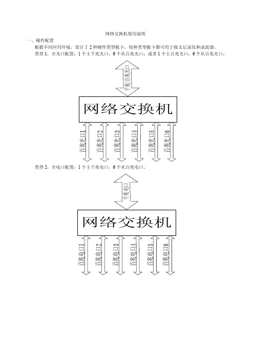
网络交换机使用说明一、硬件配置根据不同应用环境,设计了2种硬件类型板卡,每种类型板卡都可用于报文记录仪和录波器。
类型1,全光口配置:1个主千兆光口,6个从百兆光口;或者1个主百兆光口,6个从百兆光口。
类型2,全电口配置:1个主千兆电口,6个从百兆电口。
光口电口混合配置:1个主千兆光口,6个从百兆电口。
二、功能报文记录仪使用:把6个百兆口来的数据包汇聚到主网口输出。
不需要参数配置。
录波器使用:● 接收各个网口来的数据包,按照预设的目的地址组划分,转发到相应的网口输出,不设置不转发。
共7个网口,所以共有7个转发方向。
其中最顶端网口编号为1,最底端主网口的编号为7。
● 类型1全光口板的主光口默认配置速度为千兆口,主光口模块可带电插拔程序自动识别。
● 类型2主网口(光口或电口)都为千兆口。
● 使用前通过配置软件对各个数据包根据目的地址进行设置,规定其出口。
● 配置端口规定为第一个百兆网口。
三、FPGA 程序有2个程序版本,一个用于报文记录仪使用,另一个录波器用。
四、配置软件安装如果初次安装,电脑上还没有.net framework 环境则需要拷贝完整安装文件,包括以下部分:安装的时候点击setup.exe, 如果电脑上还已经有.net framework 环境,则安装时候只需安装文件即可,点击安装,按照默认一步一步安装完成后会提示是否安装,如果以前已经安装则点击否就行了,点击是重新安装也没问题。
五、配置软件使用1,主界面2,工具栏按钮说明a,下发配置:将当前配置发送到交换机;b,读取配置:将交换机配置读取到本机并显示在主界面上;c,打开配置:打开本地配置文件并显示到主界面上;d,保存配置:将主界面当前配置保存到本地配置文件;e,开始测试:启动线程,不间断的向交换机发送数据;f,停止测试:停止“开始测试”按钮开启的测试;g,中断数据:中断和交换机的数据传输;h,设置Mac:设置mac地址的范围,主界面中的mac地址在起始地址和结束地址之间循环(如果结束地址和起始地址之间的mac地址数小于总的Mac地址数)。
2524S+ 交换机说明书

4.1.2 W eb 浏览的系统需求 .......................................... 21 4.1.3 W eb 页面基本组成 ............................................ 22 4.1.4 页面选择按钮 ................................................ 22 4.1.5 各页面的详细介绍 ............................................ 23 4.2 Web 浏览会话的登陆 ............................................ 24 4.3 配置页面链接标签界面 .......................................... 24 4.4 系统配置 ...................................................... 25 4.4.1 密码设置 .................................................... 25 4.4.2 IP 地址设定 ................................................... 26 4.4.3 SNMP设置 ................................................... 26 4.4.4 交换机状态查看 .............................................. 27 4.4.5 TRUNK设置 .................................................. 27 4.4.6 VLAN 模式设置 ............................................... 28 4.4.7 广播风暴控制设置 ............................................ 28 4.4.8 恢复出厂默认设置 ............................................ 29 4.4.9 远程升级系统 ................................................ 29 4.5 端口设置 ...................................................... 30 4.5.1 端口基础设置 ................................................ 31 4.5.2 端口信息查看 ................................................ 31 4.6 VLAN 设置 .................................................... 32 4.6.1 Port Vlan ID 设置 .............................................. 32 4.6.2 VLAN Tag 设置 ............................................... 33 4.6.3 VLAN 组设置 ................................................. 34 4.6.4 VLAN 优先级设置 ............................................. 35 4.7 MAC 地址绑定设置 ............................................. 35 4.7.1 端口 MAC 地址绑定设置 ........................................ 36 4.7.2 ARL 表查询 .................................................. 36 4.8 802.1x 认证协议设置 ............................................ 37 4.8.1 Radius 服务器配置 ............................................ 37 4.8.2 802.1x 协议配置 .............................................. 38 4.8.3 802.1x 端口配置 .............................................. 38 4.9 保护 VLAN 设置实例 ............................................ 39 第 5 章 常见问题解答 ............................................... 40 附录 A 产品特征参数 ............................................... 42 附录 B 接口与网线的技术说明 ....................................... 44
以太网交换机使用说明书

以太网交换机使用说明书目录物品清单 (4)第一章用户手册简介 (5)1.1 用途 (5)1.2 约定 (5)1.3 用户手册概述 (5)第二章产品概述 (6)2.1 产品简介 (6)2.2 产品特性 (6)2.2.1 主要特性 (6)2.2.2 规格说明 (7)第三章安装指南 (8)3.1 安装 (8)3.1.1 安装在桌面上的方法 (8)3.1.2 安装在机架上的方法 (8)3.1.3 加电 (8)3.2 交换机的外观 (8)3.2.1 前面板 (8)3.2.2 后面板 (10)3.3 注意事项 (10)第四章交换机基本概念 (12)4.1 系统配置 (12)4.1.1 系统信息 (12)4.1.2 IP地址参数 (12)4.1.3 文件传输 (12)4.1.4 保存与复位 (13)4.2 端口管理 (13)4.2.1 端口参数 (13)4.2.2 端口监控 (14)4.2.3 端口描述 (14)4.2.4 端口统计与端口状态 (14)4.2.5 端口带宽 (15)4.2.6 端口广播风暴 (15)4.3 网络配置 (15)4.3.1 最大老化时间与动态地址表 (15)4.3.2 静态地址表 (16)4.3.3 静态安全地址表 (16)4.3.4 Ping检测 (16)4.4 虚拟局域网管理 (16)4.4.1 VLAN模式配置 (17)4.4.2 Global VID配置 (18)4.4.3 VLAN配置 (18)VLAN组 (19)4.4.4 MTU4.5 Trunk配置 (19)4.6 优先级管理 (20)4.6.1 优先级配置 (20)4.6.2 端口优先级表 (20)4.6.3 TOS优先级 (20)4.6.4 802.1p优先级 (20)4.6.5 802.1p优先级映射表 (21)第五章 WEB管理 (22)5.1 概述 (22)5.2 WEB管理的连接 (22)5.2.1 准备工作 (22)5.2.2 连接 (25)5.3 WEB管理界面及操作方法 (26)5.3.1 系统配置 (27)5.3.2 端口管理 (30)5.3.3 网络配置 (37)5.3.4 VLAN管理 (41)5.3.5 Trunk配置 (45)5.3.6 优先级管理 (46)第六章带外管理 (52)6.1 概述 (52)6.2 带外(out-of-out)的连接方法 (52)6.3 带外管理的界面及操作方法 (53)6.4 CLI命令使用说明 (53)6.4.1 语法帮助 (53)6.4.2 命令帮助使用说明 (53)6.4.3 常用命令 (54)管理 (58)第七章 Telnet7.1 概述 (58)7.2 Telnet的连接方法 (58)7.3 连接 (60)附录A RJ-45插座/连接器引脚详细说明 (62)物品清单小心打开包装盒,检查包装盒里应有的配件:一台交换机一根交流电源线一根串口线一本用户手册两个L型支架(KN-S1008M+除外)如果发现包装盒内产品有所损坏或者任何配件短缺的情况,请及时和当地经销商联系。
- 1、下载文档前请自行甄别文档内容的完整性,平台不提供额外的编辑、内容补充、找答案等附加服务。
- 2、"仅部分预览"的文档,不可在线预览部分如存在完整性等问题,可反馈申请退款(可完整预览的文档不适用该条件!)。
- 3、如文档侵犯您的权益,请联系客服反馈,我们会尽快为您处理(人工客服工作时间:9:00-18:30)。
S2524G智能以太网交换机声明Copyright ©2009-2010深圳市龙维科技股份有限公司及其许可者版权所有,保留一切权利。
未经龙维公司书面许可,任何单位和个人不得擅自摘抄、复制本书内容的部分或全部,并不得以任何形式传播。
为深圳市龙维科技股份有限公司的注册商标,对于本手册中出现的其它公司的商标、产品标识及商品名称,由各自由权利人拥有。
由于产品版本升级或其它原因,本手册内容有可能变更。
龙维公司保留在没有任何通知或者提示的情况下对本手册的内容进行修改的权利。
本手册仅作为产品使用指导,龙维公司尽全力在本手册中提供准确的信息,但是并不确保手册内容完全没有错误,本手册中的所有陈述、信息和建议也不构成任何明示或暗示的担保。
相关手册在本手册中所提到的交换机如无特别说明系指ECOM S2524GF ,简称为S2524GF 。
本说明手册中的图片都配有相关参数,这些参数和图片主要为您正确使用该产品提供参考。
在产品实际应用时,需要结合实际需要来配置。
技术支持用户支持邮箱:service@ 技术支持热线:4008-828-018网址:手册名称用途ECOM S2524G 智能以太网交换机使用手册详细地介绍用户如何通过WEB 界面对ECOMS2524G 智能以太网交换机进行配置和管理ECOM 10/100/1000M 智能以太网交换机快速入门详细地介绍ECOM S2524G 智能以太网交换机的硬件特性及安装过程目录前言 (3)目录 (4)第一章产品简介 (5)1.1产品概述 (5)1.2产品特性 (5)1.3产品规格 (6)第二章配置准备 (8)2.1基本配置要求 (8)2.1.1用户计算机要求 (8)2.1.2建立正确的网络设置 (8)2.2配置入门 (8)2.2.1连接设置 (8)2.2.2测试计算机与交换机是否连通 (9)第三章通过WEB页面配置 (10)3.1登录WEB网管 (10)3.1.1配置页面介绍 (11)3.1.2菜单简介 (11)3.1.3常用按钮介绍 (14)3.2配置信息 (14)3.2.1系统配置 (14)3.2.2端口配置 (15)3.2.3VLAN配置 (15)3.2.4汇聚配置 (16)3.2.5LACP配置 (17)3.2.6RSTP配置 (17)3.2.7802.1X配置 (17)3.2.8IGMP配置 (18)3.2.9镜像配置 (18)3.2.10QOS配置 (19)3.2.11安全配置 (20)3.2.12速率配置 (20)3.2.13广播风暴控制 (20)3.3状态信息 (21)3.3.1端口统计 (21)3.3.2端口信息 (21)3.3.3LACP状态 (22)3.3.4RSTP状态 (22)3.3.5IGMP状态 (23)3.3.6VeriPHY (23)3.3.7Ping配置 (23)3.4管理设备 (24)3.4.1重启设备 (24)3.4.2恢复出厂配置 (24)3.4.3软件升级 (24)3.4.4备份/恢复 (25)3.4.5退出 (25)第四章维护与常见故障处理 (25)4.1S2524G如何升级软件 (25)4.2电源系统故障 (25)4.3端口不能正常通信 (25)前言手册说明本文档用于指导您如何正确配置本产品。
请先阅读本文档,再进行操作。
目标读者本文档的目标读者为熟悉网络基础知识、并了解网络术语的网络管理员。
内容简介章节内容第1章产品简介介绍本产品的功能特性。
第2章配置准备介绍如何连接到交换机。
第3章通过WEB界面配置介绍如何通过Web页面来对本产品进行配置和管理。
第4章维护与常见故障处理介绍常见故障及处理方法。
产品简介1.1产品概述感谢您购买ECOM S2524G全千兆智能以太网交换机!ECOM S2524G为网吧、酒店、智能小区、中小企业等实现网络智能化和安全化提供了一个低成本、高可靠的解决方案。
ECOM S2524G是龙维公司自主开发的二层线速全千兆智能以太网交换产品。
该交换机提供24个10/100/1000M自适应以太网端口,可以满足您高带宽的需求。
同时,支持WEB和Console管理方式,支持端口镜像、端口汇聚、VLAN划分、快速生成树、QoS控制策略、802.1x认证等功能。
1.2产品特性◆符合IEEE802.3、IEEE802.3u、IEEE802.3ab、IEEE802.3x、IEEE802.3ad、IEEE802.1w、IEEE802.1x、IEEE802.1Q、IEEE802.1p标准;◆24个10/100/1000M自适应RJ45端口,支持端口自动翻转;◆所有端口支持半/全双工模式自动适应;◆采用存储-转发交换模式;◆支持MAC地址自学习;◆支持端口带宽控制和广播风暴控制;◆支持链路聚合,可配置8个汇聚组,每组最多24个端口,提供LACP状态显示;◆支持RSTP(快速生成树协议)及RSTP状态显示功能;◆支持IGMP(V1、V2)Snooping(组播应用)及IGMP状态显示功能;◆支持Port based VLAN、802.1Q VLAN;◆支持802.1x-RADIUS认证及IP地址过滤的安全保障策略;◆支持基于端口、802.1p和DSCP的优先级;◆支持端口镜像和端口流量统计功能;◆支持Ping配置和线缆诊断功能;◆支持配置文件导入导出;◆支持Console口管理;◆支持全中文WEB管理界面;◆动态LED指示灯,显示设备工作状态并提供简单的故障排除;◆19英寸标准机架式铁壳设计.产品规格硬件规格标准IEEE802.3、IEEE802.3u、IEEE802.3ab、IEEE802.3x、IEEE802.3ad、IEEE802.1w、IEEE802.1x、IEEE802.1Q、IEEE802.1p固定端口24个10/100/1000M自适应RJ45端口网线类型10Base-T:3/4/5类非屏蔽双绞线,支持最大传输距离100m 100Base-TX:5类非屏蔽双绞线,支持最大传输距离100m 1000Base-T:超5类非屏蔽双绞线,支持最大传输距离100mLED指示灯电源(Power)、端口状态(Link/Act)1至24、速率(Speed)1至24交换容量48GbpsMAC地址表8K转发速率10Mbps:14880PPS100Mbps:148800PPS 1000Mbps:1488000PPS外形尺寸440*180*44(mm)输入电压100V~240VAC,50/60Hz功耗<30W工作温度0ºC~40ºC存储温度-40ºC~70ºC工作湿度10%~90%RH不凝结存储湿度5%~90%RH不凝结散热方式风扇主动散热软件规格端口管理端口带宽控制支持广播风暴控制支持端口统计支持端口汇聚支持最多8组,每组最多24个端口端口镜像支持VLAN设置基于端口的VLAN支持基于802.1Q的VLAN支持(4K)生成树协议RSTP(快速生成树协议)支持组播应用IGMP(V1、V2)Snooping支持QoS设置QOS设置802.1p、DSCP配置准备2.1基本配置要求假定用户已经根据安装手册完成了设备的连线操作,在访问交换机的Web 配置页面前,用户计算机还需要满足一些基本的配置要求:2.1.1用户计算机要求安装操作系统(Windows XP/2000)安装以太网卡安装Web 浏览器(微软IE5.5或更高版本)安装并启动TCP/IP 协议2.1.2建立正确的网络设置如果是进行本地配置,在访问配置页面前必须将计算机的IP 地址与交换机配置在同一子网中。
如果是进行远程配置,计算机和交换机必须路由可达。
S2524G 交换机的缺省管理IP 地址为:192.168.2.1,子网掩码为:255.255.255.0。
指定与计算机相连的以太网端口属于管理VLAN ,缺队列调度算法严格优先级(SP)、加权轮询(WRR)安全设置802.1X 端口认证支持IP 地址过滤支持系统管理WEB 管理支持Console 管理支持LACP 状态显示支持RSTP 状态显示支持IGMP 状态显示支持Ping 配置支持线缆诊断支持配置文件导入导出支持软件升级支持包装内容装箱清单电源线ECOM S2524G 智能以太网交换机快速入门(含合格证和保修卡)固定架及螺丝脚垫省情况下,管理VLAN为VLAN1,包含所有端口。
2.2配置入门2.2.1连接设置为管理的计算机配置合适的网络地址:开始->控制面板->网络和拨号连接,右键单击“网络连接”图标,在弹出的上下文菜单中单击“属性”菜单。
选中“Internet协议(TCP/IP)”。
如下图:单击“属性”按键,设置计算机的IP地址。
在“Internet协议(TCP/IP)属性”对话框中点选“使用下面的IP地址”。
在“IP地址”中填入192.168.2.xxx(xxx的范围为2~254),“子网掩码”中填入255.255.255.0。
“默认网关”中填入192.168.2.1(即交换机默认的IP地址)(如下图)单击“确定”完成配置。
注意:进行本地配置时,请务必将计算机和交换机的IP地址设于同一子网中。
由于交换机的默认IP地址为192.168.2.1所以xxx处不能填1。
2.2.2测试计算机与交换机是否连通开始->运行->键入“cmd”->确定在命令提示符使用ping命令测试是否连通。
执行:ping192.168.2.1如果显示如下图所示,表示连接成功。
如果未能正确连接。
您可以检查:a)交换机前面板上与计算机相连端口的指示灯是否亮起,指示灯未亮表示物理上的连接不正常,可以换一根连接线。
b)检查上述TCP/IP设置是否正确。
注意:交换机的Web网管在同一时间只允许一个用户登录。
修改设备名和密码请参见3.2.1System””。
3.2.1““System第三章通过WEB页面配置3.1登录WEB网管S2524G内置WEB服务器,您可以通过WEB界面非常直观的对设备进行管理和维护。
运行网页浏览器,在地址栏中输入交换机缺省的IP地址“192.168.2.1”,如下图:按回车后将显示登录对话框,提示输入密码(如下图)默认是没有密码,单击“确认”,进入Web 网管初始界面,如下图:3.1.1配置页面介绍Web配置页面分为:标题栏、菜单栏、配置区三部分。
单击菜单栏中的菜单项,可以进入相应的页面,配置区显示设备状态信息并可进行数据配置。
3.1.2菜单简介Web网管的菜单栏包含:系统配置、端口配置、VLAN配置、汇聚配置、LACP配置、RSTP配置、802.1X配置、IGMP配置、镜像配置、QOS配置、安全配置、速率配置、广播风暴控制、端口统计、端口信息、LACP状态、RSTP状态、IGMP状态、VeriPHY、ping配置、重启设备、恢复出厂配置、软件升级、备份/恢复、退出25个菜单项。