EMG中文版说明书
[讲解]德国德瑞EMG-DREHMO电动执行器说明书
![[讲解]德国德瑞EMG-DREHMO电动执行器说明书](https://img.taocdn.com/s3/m/3179540958eef8c75fbfc77da26925c52cc59161.png)
德国德瑞EMG-DREHMO 电动执行机构主要组成及特点精工细琢、卓尔不凡DREHMO®电动执行器主要组成部件:封闭式电机、带偏心行星齿轮机构、可拔插式电气接线盒、不带离合器的手轮操作机构、组合传感器(扭矩、行程测量)、电气综合控制单元。
所有行星齿轮组件围绕着输出这心主轴安装并在任何时刻都有数个齿啮合在一起,有别于传统直齿齿轮和蜗轮蜗杆结构,其结构紧头面人物、机械效率(70~80%)高、磨擦小,使用寿命更长。
电动工作原理电机通过传动齿轮组(2)驱动装在输出轴上的偏心轮(3),带动安装在偏心轮的行星齿轮(4)。
行星齿轮与太阳齿轮(16)内齿面啮合,由于两个齿轮齿数不同,电机转动时形成相对速度,通过固定在行星轮上的随动轴(17)带动驱动圆盘(5),驱动圆盘以锯齿紧密啮合驱动空心输出轴(15)即实现阀门的启闭。
手动工和原理电机工作时,手轮保持不动。
电动变为手动时,电动执行器不需要依靠任何机械转换装置。
手动条件下,其驱动经过偏移蜗杆(13)、太阳齿轮(16)及行星齿轮(4)传递给驱动圆盘(5)最终驱动输出空心轴(15)。
过扭矩保护太阳轮(16)外齿与偏移蜗杆(13)啮合,偏移蜗杆被预设加载的弹簧(12)固定在中间部位,在扭矩超过弹簧预设值的情况下,太阳轮(4)上圆周力的变化会使移动蜗杆(13)偏移离开中间位置并通过扭矩传动杆(14)启动组合传感器。
行程位置传送输出轴传动带动嵌装其上的行程传动齿轮组转动,启动组合传感器。
工作制式调节型电动执行器:短时工作连续工作时间<15分钟,启停周期为1200次/小时。
开关型电动执行器:短时工作连续工作时间<15分钟,启停周期为600次/小时。
长寿命偏心行星齿轮传动机构独特的带偏心行星齿轮机构为DREHMO®公司享有专利的核心技术。
该传动机构在运行时永远是多点受力,减少机械磨损,大大提高了传动机构的寿命。
其机械效率是蜗轮、蜗杆传动结构的2-3倍,具有自锁功能。
EMG电动执行机构说明书
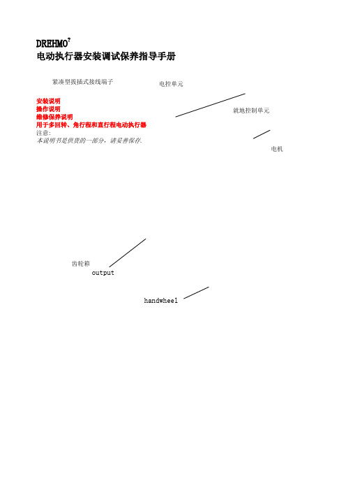
DREHMO ?电动执行器安装调试保养指导手册安装说明操作说明 维修保养说明用于多回转、角行程和直行程电动执行器注意:本说明书是供货的一部分,请妥善保存.紧凑型拔插式接线端子 电机综合说明维修手册适用于DREHMO(德瑞)电动执行器 (多回转、角行程、直行程执行器)。
安装调试执行机构之前请阅读本手册。
未遵照执行可能会导致人身或物质损害,并使所有质量保证失效。
将执行器应用到未经我们认可的场合所导致的损失我们不承担任何责任。
DREHMO?执行器的不同配置需要有下列不同的文件:据本安装、操作、维修手册接线图PROFIBUS DP特殊的PROFIBUS DP说明书这个符号代表“注意”。
未能遵照可能会产生损害。
这个符号表示“警告!”。
未能注意可能会导致人员和产品损失。
服务热线德国:Tel.: +49 (0)2762 / 612-314Fax: +49 (0)2762 / 612-359 或–466 或 -476中国: Tel: (Fax: (DREHMO电动执行器电动执行器的安全和使用注意事项(按照低压电器规范73/23/EWG)1. 总则在执行器工作中电源输入部分、移动或转动部分可能具有较高的表面温度。
非专业人员对执行器的开盖,错误的安装调试或操作可能导致严重的人员或物质损害。
其它信息请参考本手册。
所有工作(运输、安装和调试以及维修和保养)都必须由经过培训的合格人员来完成(按照DIN VDE 100 和 IEC 664以及当地国家的有关安全防护条例)。
按照本手册的安全操作规范所指的合格的人员是对DREHMO电动执行器的工作原理、安装、调试、操作都比较熟悉的人员,他们并且具备相应的职业培训。
本手册在工作时应随时携带,并对所要求的注意事项及时给予注意。
2. 合乎规范的应用电动执行器是用于对电动装置进行调控的单元。
电动执行机构的安装和调试必须按照EMV规范(89/336/EWG)进行。
技术数据、连接和操作按照有关文件和铭牌的数据,必须完全遵守。
EPC中文手册EMGDES-00004495-SPCc0126-1

操作手册SPC compact 板带对边纠偏系统用于无机械臂连接的卷取机•测量系统CCDpro•“错边”功能•数字式控制器 SPC compact / SPCc0126_1•选件: 模拟输出模块修改情况:名字: 日期:00 新版格式 + 安全措施Roet 16.09.08© 2022 EMG Automation GmbH. 版权所有本文档拷贝权归属EMG Automation GmbH. 本文所涉及的技术信息禁止以任何形式拷贝、传播或未经授权对外交流或用于竞争目的。
技术修订目录目录1安全错误!未定义书签。
1.1简介错误!未定义书签。
1.2总则错误!未定义书签。
1.3安全规程的违背错误!未定义书签。
1.4基本安全预防措施错误!未定义书签。
1.4.1地方性法规,官方指令和规程错误!未定义书签。
1.4.2应用范围错误!未定义书签。
1.5构造及目的错误!未定义书签。
1.5.1参照符号表错误!未定义书签。
1.6安全规程总述错误!未定义书签。
1.6.1技术状况介绍错误!未定义书签。
1.6.2安全防护装置的移除错误!未定义书签。
1.7具体安全规程错误!未定义书签。
1.7.1机械危险错误!未定义书签。
1.7.2电气危险错误!未定义书签。
1.7.3液压危险错误!未定义书签。
1.8责任和资质要求错误!未定义书签。
1.8.1授权人员/雇员资质错误!未定义书签。
1.9设备故障和损坏的告知责任错误!未定义书签。
1.10必要的防护服错误!未定义书签。
1.11禁止改造和变更错误!未定义书签。
1.12维护责任错误!未定义书签。
2系统的简要描述错误!未定义书签。
2.1应用错误!未定义书签。
2.2控制器SPCc 错误!未定义书签。
3工作模式错误!未定义书签。
4调试错误!未定义书签。
4.1事故预防的信息错误!未定义书签。
4.2安装错误!未定义书签。
4.2.1连接条件错误!未定义书签。
4.2.2CCD摄像头 CCDpro 5000 测量系统的安装错误!未定义书签。
EMG调试手册

二、执行器技术数据
不同系列的 DREHMO 电动执行器技术数据可以按照用户的要求打印出来给用户参考。 2.1 工作方式 DREHMO 控制执行器及调节执行器的两种 S2/S4 工作方式。
DMC/DiM 120 DMC/DiM 250
DMC/DiM 30 DMC/ DiM 59
DMC/DiM 500 DMC/DiM 60
2.2 防护形式 执行器的防护形式 IP 在执行器的铭牌上有标注。在常规配置情况下执行器是适合户外安装使用的,它能够
使用手册 第 4 页,共13页
完全防护外界粉尘的侵入,也可防护水的短时浸泡(防护等级 IP67,依照 DIN EN 60529/ IEC 529)。作为选项 也可提供防护等级为 IP68 的电动执行器。IP68 的防护标准可使执行机构在潜入水的情况下正常工作。 2.3 技术参数 供电电压 供电电流 供电频率 功率 绝缘等级 环境温度 电缆截面 按照说明书标示,单位 [V], ±10% 按照说明书标示,单位 [A] 按照说明书标示,单位 [Hz], ±3% 按照说明书标示,单位 [kW] II 按照 DIN EN 61010 -25°C 到 +70°C (DiM 系列) -25°C 到 +60°C (DiMR 系列) 最小 1.5mm2 , 适用电机功率最大到 1.6kW/400V(AC 3ph);最小 2.5mm2 适用于电机功率 最大到 8.5kW/400V (AC 3ph)对更大的电缆截面请询问。 普通的溶解保险丝或针对感应载荷(电机)的自动保护装置: 16A 用于最大到 1.6kW/400V (AC 3ph)电机测量功率。 25A 用于 1.6kW 到 8.5kW/400V (AC 3ph) 电机测量功率。 螺纹连接: 0,5 到最大 2,5 mm2 最大 230V AC 0,3 A, 30V DC 2 A (欧姆荷载) 超压范围 I ≤ 300 欧姆 <海拔 2000 米。 当 >海拔 2000 米时请咨询生产商。 因为在不同的环境温 度下对绝缘和负荷强度有不同的限制。 IP67,当使用相应的电缆导入端口且密封完好时。 也可选择 IP 68 防护等级。 在执行器内部污染度为 1 (IEC 664) 在执行器外部污染度为 2 (IEC 664) 最大 95% / 31°C 当执行器标称电压>500V 或者接触器电压>60V 时,必须将控制单元 的电势参照点 0V 同 PE 相连。在电控板上将 X9 PE 和 GND 端子短 接。 其它的技术参数请咨询办事处。 2.4 手动操作 (“手轮”) 手轮用于断电时手动调节驱动设备或阀门的位置。不需要对执行器进行从电动到手动的离合切换操作。 向右转动手轮导致驱动套的右转 (从执行器向阀门方向看)。 2.5 运输和仓储 对正确的执行器运输方式(通过吊车)在下图给出了示意。 图1: 通过吊车对执行器搬运 • • • • • • 不要将起重机械的绳索挂在手轮或电机螺栓上。 仓储在通风和干燥的房间。 安装在户外时应接上电源。 当存放在潮湿的环境时,应接通电源。 对地面的潮气进行防护(应将执行器仓储在货架或类似的撑起的支架上)。 裸露的金属表面涂上合适的防锈剂。
EMG对中系统使用手册
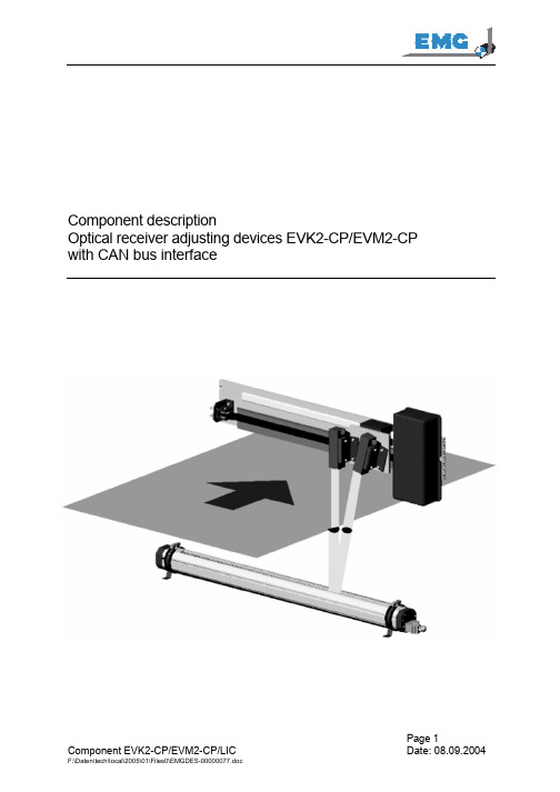
Component descriptionOptical receiver adjusting devices EVK2-CP/EVM2-CP with CAN bus interfaceSafety informationControl systems using EVK2-CP/EVM2-CP sensors are reliable electrical machines fully in accordance with up to date practice for use in industrial plants.Safety regulations serve to prevent personal injury and damage to property.Important information concerning technical safety and operational safety are marked as follows in this operating manual:CAUTION:This information must be strictly observed, in order to avoid danger topersonnel .ATTENTION: This information must be strictly observed, in order to prevent damage to or destruction of machines and machine components.NOTE:This is a reference to technical requirements which should be observed by the user of this Manual.The devices supplied shall only be transported, erected, connected, commissioned, maintained and operated by qualified personnel who are familiar with the applicable safety regulations and erection instructions. Any work carried out must be checked by responsible persons who are suitably qualified. These qualified persons must be authorised by the person responsible for plant security.Qualified persons are those who• are professionally qualified and who have relevant experience• are acquainted with applicable standards, regulations, provisions and accident prevention regulations• have been trained and are fully familiar with the functional and operational conditions of the strip centre control system• are able to detect and to avoid dangerous situationsFor regulations and definitions concerning qualified personnel, see VDE 0105 or IEC 364.Trained personnel shall only be allowed to carry out work which was covered in f their specific professional training.The use of non-qualified personnel is prohibited.Those responsible for the plant must ensure that• safety information and operating instructions are available and observed• operating conditions and technical data are observed, in accordance with the order• protective devices are used• prescribed maintenance work is carried out and maintenance personnel are immediately called and electrical machines are immediately stopped in the event of abnormalvoltages, increased temperatures, noises, vibrations etc., in order to establish the cause.This component description contains the information which is required for qualified personnel to put the system into operation and to adjust the measuring sensors EVK2-CP/EVM2-CP with an HF lamp once the supply voltage has been properly connected, in accordance with the wiring schematics. It does not include additional information either for non-qualified personnel or for using the machine in non-industrial plants.The manufacturer's guarantee only applies if all instructions in the Operating Manual are adhered to.Table of contentsinformation (1)Safetydescription (5)General1description (5)Technical22.1 Concise description of the EVK2-CP/ EVM2-CP system (5)2.2 Function of the systems with HF lamp (6)3Operation (7)3.1 Information relating to accident prevention (7)3.2 Installation (7)3.2.1 Prerequisites for connection (7)3.2.2 Installation on the measuring system (7)3.2.3 Installation of higher ranking control electronics (9)settings (10)3.3 Basic3.3.1 Compact light unit LIC (10)3.3.2 Putting the receiver adjusting device into operation (11)3.3.2.1 Aligning the measuring and reference receivers to match the lamp (13)3.3.2.2 Compensating the measuring and reference receivers (14)3.3.2.3 Aligning the reference receivers (14)4 Putting into operation (15)4.1 Selecting the operating mode (15)4.2 Amplification of 'Positioning' and 'Edge searching' (16)4.3 CAN bus communication (16)4.3.1 CAN bus addressing (16)4.3.2 CAN bus transmission rate (17)4.3.3 CAN bus protocol (17)Maintenance (19)55.1 Safetymeasures (19)work (20)5.2 Maintenance5.3 Checking the condition of the equipment (20)5.3.1 Cleaning the sheathing tubes (lamp) (20)Appendix (21)67 Notes how to setup the replacement EVK2.11 board (23)1 General descriptionApplications of EVK2-CP/ EVM2-CPIncreasing automation and the growing importance of product quality require continuous measurement of the strip edge position and the strip width in strip processing lines.For this purpose, measuring sensors type EVK /EVM are used, in order to determine the strip edge position / strip width by means of a band-pass filter of the high-frequency fraction of lamps type LIC.In a specific case, the receiver adjusting devices are controlled by control electronics connected on the load side. When using receiver adjusting devices of the type EVK2-CP or EVM2-CP, communication and control is carried out using the CANopen interface. This significantly reduces cabling as compared with the previous models EVK and EVM. Other functions and status reports are integrated in the communication protocol, so that maintenance and trouble shooting are considerably simplified.Normally a receiver adjusting device is arranged in such a manner that the photoelectric measuring beam LS13 continuously follows the changing strip edge position, accompanied by a reference photoelectric beam type LS14 which continuously checks the light intensity and compensates for possible variations .The ACTUAL position of the receiver adjusting device is measured by an internal rotary potentiometer. Digital linear path encoders may be used as an option.2 Technical description2.1 Concise description of the EVK2-CP/ EVM2-CP systemAbove the strip, at least one receiver adjusting device with an electrically adjustable slide is installed (in the case of strip centre controls or width measurements, two complete receiver adjusting devices are installed). An HF alternating light measuring unit consisting of a measuring and a reference receiver is fastened to the slide. Internally, a rotary potentiometer for measuring the ACTUAL position is attached to the DC motor.Below the strip, a lamp with a 1000 Hz power supply is installed. Supply to the lamp and to the receiver adjusting device(s) is achieved by power packs in a separate housing. Evaluation of the HF alternating light measuring equipment is carried out in the electronic system of the receiver adjusting device.2.2 Function of the systems with HF lampThe strip edge is detected by a motor-driven receiver adjusting device which is equipped with HF alternating light measuring devices LS13 / LS14 which are protected against extraneous light. If the strip edge is displaced as a result of a change in the strip width or in the strip run, this variation is detected by the photoelectric beams. The higher ranking control electronics activate the DC motor or the actuator in the control circuit, in order to ensure that the strip edge always covers half the measuring range of the photoelectric measuring beam.In order to compensate for variations, the optical transmitters, the reference measuring method is applied, i.e. a measuring receiver and a reference for each item of measuring equipment are focussed on the same light spot as the optical transmitter. While the measuring receiver detects the lateral position of the strip edge, the reference receiver measures the background brightness of the light spot.Elimination of influences from extraneous light is vital for the accuracy of measurement. This is ensured by HF light transmitters and selective HF alternating light receivers, the band pass evaluation being carried out in the EVK2-CP electronics. The light intensity emitted by the transmitters is controlled and monitored for failure.Parameterising of the complete system is carried out using a Laptop or a PC, or by means of the keyboard diagnostic unit connected to the control electronics. Provided that the voltage supply is correctly wired , complete alignment of the measuring sensors is also possible without CAN bus communication.HF alternating light measuring equipment protected against extraneous lightIn order to avoid the influence of extraneous light on the strip position detection system, the types of lamps actually used (LIC) are operated by a 1000 Hz supply voltage. The measuring signals of the HF alternating light measuring equipment are guided through appropriate filters, and only the high-frequency light signal is evaluated.The brightness of the lamps is kept at a constant level by an internal control circuit , so that the measuring equipment is not influenced by extraneous light or variations in voltage or temperature.3 Operation3.1 Information relating to accident preventionWhen connecting and operating the system, make sure that the protective system prescribed by VDE 0100 is used.In addition, generally applicable safety regulations and provisions for operational safety shall be observed.Caution: There is a pinch hazard when moving the measuring equipment on the receiver adjusting devices. Before connecting the adjusting devices, make sure thatmovement is possible without any risk.3.2 InstallationNote: The devices should be unpacked in a closed and dry building immediately before their installation. Check the condition of the equipment (brightcomponents, protective coating, etc.). Retouch if necessary.Transport guards and preserving material should only be removed immediately before the equipment is installed.3.2.1 Prerequisites for connectionThe exact dimensions required for installation of the equipment are specified in the relevant drawings.3.2.2 Installation on the measuring systemNOTE: Select the installation position so that fluorescent tubes may be replaced easily.- Fasten the receiver adjusting device (EVK) figure 3-1 in such a manner that the minimum strip width <d> and the maximum strip width <c> are symmetrically lying within the adjusting area <a>. The reference point for the installation is <f>.- Align the receiver adjusting devices <1> and <2> parallel to the lamps <3>. The travelling axes and the centre lines of the lamp must be parallel.- Install the lamp in such a manner that the useful length <e> is within the adjusting range<a> of the receiver adjusting device.The permissible distance between the lamp and the receiver is L = 300 ... 4 000 mm.The permissible distance between the lamp and the strip is: X ≥ 175mm + (0.13 ·L).Figure 3-1A Arrangement of the EVK and the lamps in the equipment1 EVK2-CP left-hand2 EVK2-CP right-hand3 Lamp (LIC...)a. EVK stroke d. Minimum strip widthb. Centre of equipment e. Useful length of lamp LICc. Maximum strip width f. Reference pointFigure. 3-1B Arrangement of the EVM and the lamps in the equipment1. EVM2-CP2. Lampa. Maximum strip width d. Reference pointb. Minimum strip width e. Useful length of lampc. Centre of equipmentL. Distance lamp - receiver L = 300 ... 4000 mmX. Distance lamp - strip X ≥ 175 + 0,13 · LGeneral:Measuring receivers figure 3-2 <2> must be aligned at right angles to the strip <3>.Note: While the optical beam of the measuring receiver is half covered by the strip, the reference receiver <1> views the remaining light spot on the lamp <4>. Bysuitable arrangement of the receiver adjusting device (EVK) and the lamp <4> itmust be ensured that the optical beam of the reference receiver <1> is nevercovered to any extent at all.Figure 3-2 Arrangement of the HF measuring receivers and the HF reference receivers1 Reference receiver 3 Strip2 Measuring receiver 4 Lamp (LIC...)L Distance lamp – receiver L = 300 ... 4 000 mmX Distance lamp – strip X ≥ 175mm + (0,13 · L)3.2.3 Installation of higher ranking control electronics- When installing the control electronics, take account of the ambient conditions.- Protect the system from direct heat radiation, humidity and strong vibration.- Carry out wiring in accordance with the wiring schematics. Special attention should be given to correct wiring and to the correct type of CAN bus cable including shielding.3.3 Basic settings3.3.1 Compact light unit LICFunctional descriptionThe light unit compact LIC emits controlled, 2kHz alternating light, which can be synchronized with respect to frequency and phase when two lamps are used. The light generating element is a fluorescent tube with special "electronic ballast" with the following functions:• Ignition of the lamp• Operation of the lamp as controlled 2kHz-AC light source • Synchronisation of two lamps (by connecting the Sync cable) • Information on the lamp statusThe LIC light unit is factory set and requires no further calibration during installation.Figure 3.3 Block diagram of LIC supplyTypeSupply voltage to 24VDC Capacity int. heatingFluorescent tubes ∅ 26mm, colour 840 LIC 480 2.2 A 31 W L18W, 590mm LIC 770 2.8 A 35 W L30W, 895mm LIC 1075 3.7 A 69 W L36W, 1200mm LIC 13754.0 A 60 WL58W, 1500mmTemperature range Storage and transport: -25... +85 °C Operation:0... +50 °CProtective system IP54EN60529X1+24DC 0V LIC_ok Sync3.3.2 Putting the receiver adjusting device into operationThe travelling distance of the receiver adjusting device is factory-set to the maximum inner and outer positions. If these settings must be changed (for reasons of the mechanical installation situation or fitting a spare device), the inner end position may be changed by rotating the sliding clutch between motor and potentiometer. The outer end position may be changed using a Laptop and the terminal programme.Checking the function of the limit switch of the receiver adjusting devices- Remove the cover of the EVK electronics and move the slide to the strip centre or to the strip edge by means of keys S31 and S32 figure 3-4 (following selection of manual operation by means of S4/2); LED H6 <3> will signal 'ready for travel' or 'not in end position'.- Once the "inner end position' or the 'outer end position' is reached LED H6 will go out, and the slide can be moved in the opposite direction.NOTE: The inner end position is determined by the potentiometer voltage and may be changed as follows:Move the slide into the inner position and measure its actual travel at test socketW. The slide stops at 0V DC. By rotating the sliding clutch between motor andpotentiometer the limit switch position may be changed as required.When the inner end position is changed, the value for the outer end position isalso changed. Therefore, it should be checked, if necessary. The value for theouter end position is determined according to the EVK stroke with a scaling of1V/100 mm (e.g. EVK600 should indicate 6V in the outer end position).The outer end position is factory-set with a scaling of 1V/100 mm. Modification ofthe software using a Laptop is possible but not necessary for line operation. Inaddition, the control electronics offer the possibility of limiting the stroke of theadjusting device electronically by activating the motor (e.g. for masking edges oftransition tables).1V/100 mm standardisation must be checked by travelling the full stroke of theadjusting device (measuring at test socket W against GND) and scaled by meansof potentiometer R30, if necessary.Figure 3-4 Electronics EVK2.11 (Supplementary cards EVK2.12/EVK2.13 at an optional extra see fig. 6-1)1 2 3 4 5 6 7LED H1 ... H8 Measuring sockets MES1,REF1,W, GND LED H10 (LIC o.k.) Rotary switch S4 test functions Key S31/S32 (manual operation) Potentiometer R1/R2 MES/REF Key S6 (Reset)8 9 10 11 12 13 Jumper J9 Terminating resistance CAN bus Hex. switch S50/S51 CAN bus address Switch S2 function switchSwitch S3 CAN bus configuration Potentiometer R30 Path scaling Plug X21 for Laptop connectionTerminal operation1110123.3.2.1 Aligning the measuring and reference receivers to match the lamp- Place potentiometers R1 and R2 in a central position (when using adjusting devices of the type EVM, put R3 and R4 to Subprint EVK2.12);The field of vision of the receivers must be clear!Aligning the measuring receiver according to suit the strip pass level- Pivot the measuring receiver figure 3-5 <1> transversally to the strip pass direction, align it at an angle of 90° with respect to the strip pass level and tighten the corresponding Allen screws.- Connect a measuring instrument to sockets Mes .. and GND figure 3-4 <2>.- Pivot the measuring receiver in the strip pass direction figure 3-5 <4> and tighten the Allen screws at the maximum voltage value.Aligning the reference receiver to accord with the strip pass direction- Connect a measuring instrument to sockets Ref .. and GND figure 3-4 <2>.- Pivot the reference receiver figure 3-5 <4> in the strip pass direction, tighten the corresponding Allen screws at the maximum voltage value.Figure 3-5 Arrangement of the receivers1 Measuring receiver 3 Lamp2 Reference receiver 4 Strip pass direction3.3.2.2 Compensating the measuring and reference receiversLevel the measuring and reference receivers in accordance with the table below.Receiver Measuring pointEVK2.11/EVK2.12 Compensating inV on themeasuringsockets on theEVKAdjustingpotentiometerEVK2.11/ EVK2.12Photoelectric measuring beam 1 – AS MES 1 10V DC R1 Photoelectric reference beam 1 – AS REF 1 5V DC R2 Photoelectric measuring beam 2 – BS MES 2 ** 10V DC R3 ** Photoelectric reference beam 2 – BS REF 2 ** 5V DC R4 ****only available when using adjusting device EVM2-CP on Subprint EVK2.12.3.3.2.3 Aligning the reference receivers- Connect an external measuring instrument to measuring sockets MES .. and GND figure 3-4 <2> on the receiver adjusting device.- Cover the measuring range of the receiver by a cardboard strip with a minimum width of 100 mm - commencing in the centre of the equipment. Place the strip directly onto the lamp, so that the external measuring instrument reads 2.5 V.Connect an external measuring instrument to measuring sockets REF .. and GND figure 3-4<2> on the receiver adjusting device.- Pivot the reference receiver transversally to the strip pass direction, see figure 3-5 <4>, so that the external measuring instrument reads 2.5 V, tighten the screws.- Check both voltage values on sockets MES .. and REF .. (2.5V).Readjust, if necessary.- In the case of EVM – devices, the above alignment must be carried out for both pairs of photoelectric beams. The additional measuring points and the adjusting potentiometer are located on Subprint EVK2.12.4 Putting into operationIn addition to the mechanical adjustment of the photoelectric beams and subsequent compensating by means of the potentiometer, the following steps must be carried out for electrical adjustment.4.1 Selecting the operating modeWhen using motherboard EVK2.11 in combination with Subprints EVK2.12 (as an electronic system for EVM) or EVK2.13 (reading of an attached SSI-path encoder), selector switch S2 must be positioned in accordance with table 4-1. Furthermore it is possible to guide the signals of the photoelectric beams and the actual path value through an internal software filter.DIP switch ON OFF RemarksS2_1 EVM EVK EVM operation; evaluation of pair of receivers twiceS2_2 SSI pathencoderInternalpathsensorThe actual value of the SSI path encoder with an absoluteaccuracy of 1/10mm is used as the actual position value insteadof the internal potentiometer. This value is transmitted via theCAN bus and it is valid for positioning and monitoring of the endposition.S2_3 freeS2_4 FilteractiveNo FilterPT1 links for the signals of the photoelectric beams and for theinternal path sensor may be connectedTable 4-1 Summary of function switches S2Rotary switch S4 Operating mode - Test functions0 *) Normal operationWhen adjusting according to the terminal programme, it will react with a delay of approx. 30s!F Terminal test operationwill only react following reset!Connection EVK2.11 - PC via RS 232Functions can be selected as menu items1 'Searching the edge' Preadjustment of the controller for strip edge searchingwith R 61 controller compensating2 'Manual' Operation using the hand keys,3-step speed adaptation3 'Positioning' Positions the EVK to 100mmwith R 62 controller compensating (alternating with item 4)4 'Positioning' Positions the EVK to 150mmwith R 62 controller compensating (alternating with item 3)*) factory settingTable 4-2 Summary of function switch S4 for selecting test functions for sensorcompensating4.2 Amplification of 'Positioning' and 'Edge searching'The basic amplification for the operating mode 'Positioning' is adjusted directly on the receiver adjusting device. For this purpose, the software includes an internal test programme on board EVK2.11 which is adjusted as follows:Selection of the programme by means of function switch S4/3 or S4/4 (normal operation position 0).By changing between positions S4/3 (100mm) and S4/4 (150mm) the receiver adjusting device is moved between two positions. The amplification may be adjusted using potentiometer R62, so that the adjusting device approaches the selected position without overshoot.For the mode 'Search strip edge', a specimen of the strip must be inserted in the measuring area, at strip pass level.Selection of the test programme by means of function switch S4/1 (normal operation position 0). When moving the specimen, the adjusting device follows the lateral movement. The amplification must be adjusted on the EVK2.11 electronics by means of potentiometer R61.Parallel to the adjustment of the amplification on the EVK, adjustment by means of the digital control amplifier is possible. For the configuration, please see the system description for the overall control system.4.3 CAN bus communication4.3.1 CAN bus addressingThe address is entered in the CAN bus network by means of selector switches S50 and S51. Switch S50 is for low byte, and switch S51 is for high byte.The default address entered in the CAN bus network by EMG for the first receiver adjusting device is "04"hex. When using a second device, the address “05”hex is programmed (e.g. when using two EVKs for strip centre control). For the addresses of further adjusting devices (required for example for centering a stitch welding seam), please see the operating manual or the wiring diagram.The last receiver in the CAN network indicated in the wiring diagram (will be seen where there is no wire leaving the terminal strip X33) must be followed by jumper J9, in order to ensure that the 120 Ω terminating resistance is active.4.3.2 CAN bus transmission rateThe transmission rate is set by DIL switch S3. The transmission rate is determined in the planning phase. It depends, amongst other factors, on the overall cable length and on the number of receivers in the CAN network. For modification of the transmission rate or deviation from the factory-set value, please see the operating manual for the overall system.DIL switch S3Baud rate1 2 3 4 CANopen interface configuration0 0 x x 1 MBaud1 0 x x 500 kBaud0 1 X x 250 kBaud *)1 1 x x 125 kBaudx x x 1 **) **) 1 : synchronous transmission PDO1**) 0 : asynchronous transmission PDO1 *)*) factory settingTable 4-3 Adjustment of the transmission rate by means of switch S34.3.3 CAN bus protocolThe EVK 2.11 electronics provides two static sending words (TxPDO) and one static receiving word (RxPDO) in the CAN network. Assignment and type of communication cannot be changed. The second sending word is transmitted at a cycle rate of 25ms and contains exclusively the non-compensated measuring values of the adjusting device. Normally, these may be neglected and they are only transmitted at the request of the CAN bus master. Sending word 1 (TXPDO1) is transmitted via the bus asynchronously every 5 ms (EVK 2.11 basic cylce) or, in the case of S3_4 ON, synchronously the request of the master (min. 5ms repeating time).Databyte no.:Name Data type Remark1, 2 Edge positionLS1Signed integerEdge position corrected on the basis of values ofthe photoelectric beams(Mess1-Ref1)*Refmax/Ref1Transmission in mV/digit; range +/- 5.000 digits3, 4 Edge positionLS2Signed integerEdge position corrected on the basis of values ofthe photoelectric beams(Mess2-Ref2)*Refmax/Ref2Transmission in mV/digit; range +/- 5.000 digits5, 6 Actual path valueEVKSigned integerAbsolute position of the slideResolution: 0.1mmRange:Analogue path encoder 0 ... + 32000 digitsDigital path encoder 0 ... + 32000 digits7, 8 EVK status Unsigned integer see bit designation EVK_StatusSignal nameBinarySignalFlashing cycle EVK 2.11 Bit 00/1 Power pack ok = 1 Bit 1 0/1 Motor current ok = 1 Bit 2 0/1 End position AS (drive) = 1 Bit 3 0/1 End position CL (Centre line) = 1 Bit 4 0/1 LS 1 > 60 % = 1 Bit 5 0/1 LS 2 > 60 %= 1 Bit 6 0/1 LS 1 > 20 % = 1 Bit 7 0/1 LS 2 > 20 % = 1 Bit 8 0/1 Target reached = 1 Bit 9 0/1 Quick_Stop (feedback) = 1 Bit 10 0/1 Remote (Terminal operation) = 0 Bit 11 0/1 CAN_Bus_ok = 1 Bit 12 0/1 CAN_Overload = 0 Bit 13 0/1 LIC ok = 1 Bit 14 0/1 EVK status BitEVK ok= 1Bit 150/1These status bits must be evaluated in the control electronics.Assignment of receiving word (RXPDO1) (Input EVK2.11 via CAN bus) as follows:Data byte no.:NameData type Remark1, 2 Motor reference value EVKSigned integerInput signal motor activation +/- 10 bit for +/- 100% + direction CL- direction housing3, 4 Position reference value EVKUnsigned Integer Absolute EVK path value for1000 mm with a 1/10 mm resolution 5, 6Operating mode EVKUnsigned Integersee bit designation EVK_Operating modeBit designation EVK_Operating mode:Signal nameBinarySignal Priority *RemarksQuick Stop (command) Bit 0 0/1 0 Active when selected Auto Edge searching Bit 1 0/1 4 Auto Positioning Bit 2 0/1 3Manual AS ( Drive side)Bit 3 0/1 Manual CL ( Centre Line) Bit 4 0/1 Only active in the manual modeManual Bit 5 0/1 1Motor reference value_ON Bit 6 0/1 2 Release motor ref. valueBit 7-14 0/1 Not usedEVK_ Operating modeRelease EVK-PDO2Bit 150/1Transmission of measuring signals TxPDO2* highest priority: 0In the case of simultaneous transmission of bits for the different operating modes and possible conflicts, the priority as quoted above will apply.5 Maintenance5.1 Safety measuresBefore starting maintenance work, make sure that the following safety measures have been carried out:- The system must be switched off!- The system must be protected against unintended voltage supply!- Check the system for off condition.- If all moving parts have come to a standstill, any existing mechanical locks must be activated.- The local safety regulations and the provisions for operational safety must be complied with.Attention:The PCP is equipped with components which may be damaged by electrostatics (EGB). Intervention at switching points must be carried out by trained staff, takingdue account of the ESD protective measures.5.2 GeneralinformationThe system requires minimum maintenance work. With the exception of visual inspections and cleaning, no special maintenance is required. Replacement of components is only necessary in the case of a failure.5.3 MaintenanceintervalsMaintenance work Maintenance intervalsClean the lamp sheathing tube Clean the lenses of the photocells Replace the fluorescent tube check weekly, clean if necessary check weekly, clean if necessary every 8000 operating hours。
EMG纠偏系统说明书

16 17
17 17 17 17 18 19 19 20
Document No.: EMGDES-00004125 Designation: Operating manual
File name: BH_SPCc0101_00_en
3/52
SPC compact
4.2.7 4.2.8 4.2.9 4.2.10 4.2.11 4.3 4.3.1 4.3.2 4.3.3 4.3.4 4.3.5 4.3.6 4.3.6.1 4.3.6.2 4.3.6.3 4.3.6.4 4.3.6.5 4.3.6.6 4.3.6.6.1 4.3.6.6.2 4.3.6.7 4.3.6.7.1 4.3.6.8 4.3.6.9 4.3.6.10 4.3.7 4.3.8
Subject to technical alterations
Document No.: EMGDES-00004125 Designation: Operating manual
File name: BH_SPCc0101_00_en
2/52
SPC compact
Table of Contents
WARNING
Death or serious bodily injury. As a result of inappropriate action undertaken with components of the plant. The chapter entitled "Safety" must be read and fully understood by all persons who are responsible for operation, maintenance or repair work.
EMG电动执行机构说明书
DREHMO电动执行器安装调试保养指导手册安装说明操作说明维修保养说明用于多回转、角行程和直行程电动执行器注意:本说明书是供货的一部分,请妥善保存.紧凑型拔插式接线端子 电机综合说明维修手册适用于DREHMO(德瑞)电动执行器(多回转、角行程、直行程执行器)。
安装调试执行机构之前请阅读本手册。
未遵照执行可能会导致人身或物质损害,并使所有质量保证失效。
将执行器应用到未经我们认可的场合所导致的损失我们不承担任何责任。
DREHMO?执行器的不同配置需要有下列不同的文件:•据本安装、操作、维修手册•接线图•PROFIBUSDP特殊的PROFIBUSDP说明书这个符号代表“注意”。
未能遵照可能会产生损害。
这个符号表示“警告!”。
未能注意可能会导致人员和产品损失。
服务热线德国:Tel.:+49(0)2762/612-314Fax:+49(0)2762/612-359或–466或-476中国: Tel: (Fax: ()DREHMO电动执行器电动执行器的安全和使用注意事项(按照低压电器规范73/23/EWG)1.总则在执行器工作中电源输入部分、移动或转动部分可能具有较高的表面温度。
非专业人员对执行器的开盖,错误的安装调试或操作可能导致严重的人员或物质损害。
其它信息请参考本手册。
所有工作(运输、安装和调试以及维修和保养)都必须由经过培训的合格人员来完成(按照DINVDE100和IEC664以及当地国家的有关安全防护条例)。
按照本手册的安全操作规范所指的合格的人员是对DREHMO电动执行器的工作原理、安装、调试、操作都比较熟悉的人员,他们并且具备相应的职业培训。
本手册在工作时应随时携带,并对所要求的注意事项及时给予注意。
2.合乎规范的应用电动执行器是用于对电动装置进行调控的单元。
电动执行机构的安装和调试必须按照EMV规范(89/336/EWG)进行。
技术数据、连接和操作按照有关文件和铭牌的数据,必须完全遵守。
3.运输、仓储有关运输、仓储等的注意事项请参照执行。
EMG调试及接线图
德国EMG电动执行机构调试步骤德国EMG电动执行怎么使用?德国EMG电动执行步骤需要很好的注意。
德国EMG电动执行机构调试步骤:◆DREHMO(德国)(SFEUANFRIEBE/ACFUATORS)执行器调试操作步骤◆按功能键,显示出主菜单,在主菜单中按↑、↓键选择Learn Mode(学习方式)菜单,按功能键进入菜单。
◆选择Parameters(方向),在众菜单中选择Valve(阀门),在Valve(阀门)中选择菜单Closing Direction(设定方向)◆在Closing Direction 中根据阀门类型选择Couterlowise Open(逆时针开)或Clowise Open(顺时针开)开方向。
◆继续选择Valve(阀门)菜单中的Final Position Linmit Sw(最终位置设定)菜单,在此菜单中选择适合阀门跳断的类型。
◆按设置键进入Local,Learn moba连续按↓键选择◆按Esc键退出至Learn Mode(学习模式)菜单下● 连续按↓进入Change finol positions(改变阀门位置)● 按确认键进入Clear position close(显示位置关)● 连续按↓进入Set position close (预备关设定)● 按确认键进入sition close 0%===========100%● 然后按↓↑键操作阀门要求关的实际位置,当阀门实际动作位置符合要求时,按确认键。
● Oper操作步骤同上。
● 按Esc键退出至主菜单,选择Local(就地)或Remote(远控)模式,设定完成。
◆接线图如下:● X2端子排:PE 2(U相)、4(V相)、6(W相)● X1端子排:20与17短接、21与16短接● X1端子排:5(COM)、6(开到位)、7(关到位)● X1端子排:13(COM)、14(故障常闭)、15(故障常开)根据情况设定。
● X1端子排:23(+)、24(-)为4~20mA反馈信号。
EMG电动执行器中文版使用说明书MATIC C使用手册(V1[2][1].17)
输出轴,设备的连接....................................................................................................... 7
A 型驱动套的拆卸与安装..................................................................................
左侧电气行程限位(WL2)的设定.................................................................................. 13
机械位置指示器.............................................................................................................. 13
DREHMO® -Matic C
一体化电动执行器安装、调试、维护手册
该手册适用于开关型、步进型和调节型电动执行机构
DREHMO
安装说明 操作说明 维护说明 适用于多回转、角行程和直行程电动执行器
注意: 本手册是供货的一部分,请妥善保存以备将来使用.
T.-Nr. 166648 版本:1.15 版本日期:2006 年 7 月 25 日
这个符号代表 “注意”。 未能遵照执行可能会产生损害。
这个符号表示“警告!”。 未能遵照执行可能会导致人员和设备损失。
有关电气设备的工作及电动执行器的任何电气安装工作都必须由电工或完全在合格 工程师的监督下按照当地的电气规程来完成。
技术服务 如需技术支持和服务,请联系德瑞中国办事处或负责该项目的相应代理商。 如您的产品未从德瑞中国办事处或授权代理商处采购,德瑞中国将不提供质量保证,并且只能提供有偿 的售后服务及技术支持。
EMG电动门中文说明书
DREHMO ®电动执行器安装调试保养指导手册安装说明 操作说明维修保养说明用于多回转、角行程和直行程电动执行器注意:本说明书是供货的一部分,请妥善保存.齿轮箱综合说明维修手册适用于DREHMO(德瑞)电动执行器 (多回转、角行程、直行程执行器)。
安装调试执行机构之前请阅读本手册。
未遵照执行可能会导致人身或物质损害,并使所有质量保证失效。
将执行器应用到未经我们认可的场合所导致的损失我们不承担任何责任。
DREHMO®执行器的不同配置需要有下列不同的文件:•据本安装、操作、维修手册•接线图• PROFIBUS DP特殊的PROFIBUS DP说明书这个符号代表“注意”。
未能遵照可能会产生损害。
这个符号表示“警告!”。
未能注意可能会导致人员和产品损失。
服务热线德国:Tel.: +49 (0)2762 / 612-314Fax: +49 (0)2762 / 612-359 或 –466 或 -476中国: Tel: (021-********/32201289)021-********Fax: (021-********) 021-********DREHMO电动执行器电动执行器的安全和使用注意事项(按照低压电器规范73/23/EWG)1. 总则在执行器工作中电源输入部分、移动或转动部分可能具有较高的表面温度。
非专业人员对执行器的开盖,错误的安装调试或操作可能导致严重的人员或物质损害。
其它信息请参考本手册。
所有工作(运输、安装和调试以及维修和保养)都必须由经过培训的合格人员来完成(按照DIN VDE 100 和 IEC 664以及当地国家的有关安全防护条例)。
按照本手册的安全操作规范所指的合格的人员是对DREHMO电动执行器的工作原理、安装、调试、操作都比较熟悉的人员,他们并且具备相应的职业培训。
本手册在工作时应随时携带,并对所要求的注意事项及时给予注意。
2. 合乎规范的应用电动执行器是用于对电动装置进行调控的单元。