开关电源RSP-750-spec
SilverStone OLYMPIA OP750 电源说明书

50 mS (Tvout_on) of each other during turn on of the power supply. Each output voltage
shall fall out of regulation within 400 mS (Tvout_off) of each other during turn off. Figure 1
conditions. Any dropout of the AC line shall not cause damage to thepout is defined as a drop in AC line to 0VAC at any phase of the AC
Output Voltag Max. Load Min. Load
Max. Combined Total Output
+5V 30A 1.0A
+3.3V 28A 0A 180W 730W
+12V 60A 3A 60A
-12V 0.5A 0A
6W
+5VSB 4A 0.1A
15W
Table 5 - Output Loads Range 1j Note jMaximum continuous total DC output power should not exceed 750 W.
01
line for any length of time.
OLYMPIA OP750
3. DC Output Specification
3-1. Output Current / Loading The following tables define two power and current rating. The power supply shall meet both static and dynamic voltage regulation requirements for minimum load condition.
PowerFlex 750-Series 控制节板远程安装套件指南说明书
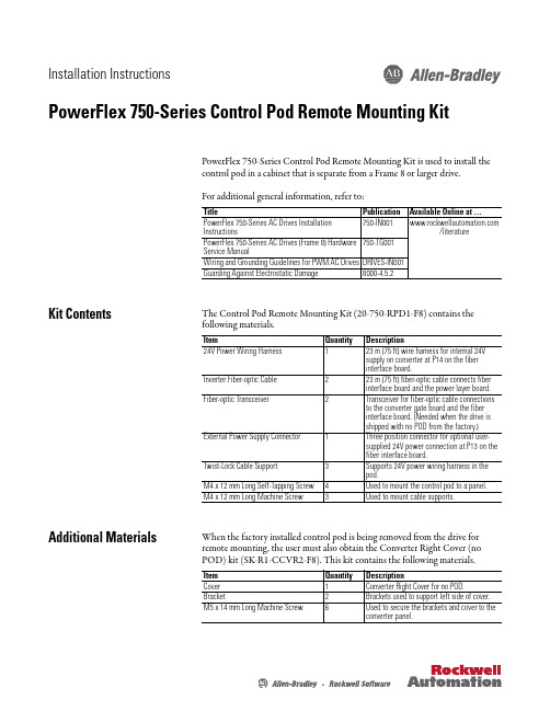
Installation InstructionsPowerFlex 750-Series Control Pod Remote Mounting Kit PowerFlex 750-Series Control Pod Remote Mounting Kit is used to install the control pod in a cabinet that is separate from a Frame 8 or larger drive.For additional general information, refer to:Kit ContentsThe Control Pod Remote Mounting Kit (20-750-RPD1-F8) contains the following materials.Additional Materials When the factory installed control pod is being removed from the drive forremote mounting, the user must also obtain the Converter Right Cover (noPOD) kit (SK-R1-CCVR2-F8). This kit contains the following materials.Title Publication Available Online at …PowerFlex 750-Series AC Drives Installation Instructions /literature PowerFlex 750-Series AC Drives (Frame 8) Hardware Service Manual 750-TG001Wiring and Grounding Guidelines for PWM AC Drives DRIVES-IN001Guarding Against Electrostatic Damage 8000-4.5.2Item Quantity Description 24V Power Wiring Harness 123 m (75 ft) wire harness for internal 24V supply on converter at P14 on the fiber interface board.Inverter Fiber-optic Cable 223 m (75 ft) fiber-optic cable connects fiber interface board and the power layer board.Fiber-optic Transceiver 2Transceiver for fiber-optic cable connections to the converter gate board and the fiber interface board. (Needed when the drive is shipped with no POD from the factory.)External Power Supply Connector 1Three position connector for optional user-supplied 24V power connection at P13 on the fiber interface board.Twist-Lock Cable Support 3Supports 24V power wiring harness in the pod.M4 x 12 mm Long Self-Tapping Screw 4Used to mount the control pod to a panel.M4 x 12 mm Long Machine Screw 3Used to mount cable supports.Item Quantity DescriptionCover 1Converter Right Cover for no POD.Bracket 2Brackets used to support left side of cover.M5 x 14 mm Long Machine Screw 6Used to secure the brackets and cover to theconverter panel.2PowerFlex 750-Series Control Pod Remote Mounting KitGeneral Precautions Read the following precautions before you begin working on the drive.Qualified PersonnelATTENTION: Only qualified personnel familiar with adjustable frequencyAC drives and associated machinery should plan or implement theinstallation, start-up and subsequent maintenance of the system. Failureto comply may result in personal injury and/or equipment damage.Personal SafetyATTENTION: To avoid an electric shock hazard, verify that the voltage onthe bus capacitors has discharged completely before servicing. Measurethe DC bus voltage at the -DC and +DC TESTPOINT sockets on the front ofthe power module (see Removing Power from the Drive on page4 forlocation).Product SafetyATTENTION: This drive contains ESD (Electrostatic Discharge) sensitiveparts and assemblies. Static control precautions are required wheninstalling, testing, servicing or repairing this assembly. Componentdamage may result if ESD control procedures are not followed. If you arenot familiar with static control procedures, reference Guarding AgainstElectrostatic Damage, publication 8000-4.5.2 or any other applicable ESDprotection handbook.Class 1 LED ProductATTENTION: Hazard of permanent eye damage exists when using opticaltransmission equipment. This product emits intense light and invisibleradiation. Do not look into module ports or fiber-optic cable connectors.PowerFlex 750-Series Control Pod Remote Mounting Kit3 Commonly Used Tools Service ToolsThis list covers the tools needed for kit installation.Fastener/Tool/Torque Information The disassembly illustrations in this publication identify the type of fastener, tool, and tightening torque used for disassembly/assembly of components in the drive:IMPORTANT Care must be taken to ensure that tools and/or hardware components do not fall into open drive assemblies. Do not energize the drive unless allloose tools and/or hardware components have been removed from thedrive assemblies and enclosure.Tool Description DetailsESD-protected place of work Working surface, Floor covering, seat and ground connections ESD-protective clothing Wrist wrap, shoes, overall clothing (coat)Multi meter Digital multi meter, capable of ac and dc voltage, continuity,resistance, capacitance measurements, and forward diode biastests. Fluke model 87 III or equivalent.Flat nose screw driver 5 mm (0.19 in.), 6.4 mm (0.25 in.)Hexalobular screw driver/bit#20, #25Phillips® screw driver/bit(1)(1)Phillips® is a registered trademark of the Phillips Screw Company.#2Torque wrench1...12 N•m (8.8…106 lb•in)Tool Type and Size:Px Phillips screw driver/bit and sizeTxx Hexalobular screw driver/bit and sizeFastener/Tool/Torque Information:4PowerFlex 750-Series Control Pod Remote Mounting KitRemoving Power from the Drive 1.Turn off and lock out input power. W ait five minutes.2.Verify that there is no voltage at the drive’s input power terminals.3.Measure the DC bus voltage at the -DC and +DC TESTPOINT socketson the front of the power module. ATTENTION: To avoid an electric shock hazard, verify that the voltage onthe bus capacitors has discharged completely before servicing. Measurethe DC bus voltage at the -DC and +DC TESTPOINT sockets on the front ofthe power module (see below for location).Remove power before making or breaking cable connections. When youremove or insert a cable connector with power applied, an electrical arc mayoccur. An electrical arc can cause personal injury or property damage by:•sending an erroneous signal to your system’s field devices, causingunintended machine motion•causing an explosion in a hazardous environmentElectrical arcing causes excessive wear to contacts on both the module andits mating connector. Worn contacts may create electrical resistance.PowerFlex 750-Series Control Pod Remote Mounting Kit5 Minimum Clearances The control pod must be mounted in a vertical orientation as shown and mustmake full contact with the mounting surface.•Do not use standoffs or spacers.•Inlet air temperature must not exceed 50 °C (122 °F).•Enclosure is rated IP00, NEMA/UL Open Type.6PowerFlex 750-Series Control Pod Remote Mounting KitApproximate Dimensions ArrayDimensions are in millimeters and (inches).PowerFlex 750-Series Control Pod Remote Mounting Kit7Remove Pod Assembly From Enclosure 1.Access the drive enclosure.2.Remove the control pod cover.3.Disconnect the factory installed internal 24V power supply cable fromP14 located on the fiber interface board.4.Disconnect the factory installed inverter fiber-optic cable from the P1(INV1) fiber-optic transceiver located on the fiber interface board. Description➊Internal 24V Power Connection Two point connector to P14.➋Inverter Fiber-optic Connection Fiber-optic cable to P1 fiber-optic transceiver INV1.8PowerFlex 750-Series Control Pod Remote Mounting Kit5.Loosen the captive screws on the back panel of the control pod until they6.Rotate the control pod to expose the hinge.7.Remove the four M4 x 12 mm screws that secure the control pod to theconverter control panel right side wall and remove the control pod. Ifdesired, the hinge can be removed from the control pod.PowerFlex 750-Series Control Pod Remote Mounting Kit9 8.Disconnect the factory installed internal 24V power supply cable fromconverter terminal block TB1 mounted on the converter control panelright side wall.9.Disconnect the factory installed inverter fiber-optic cable from the INVtransceiver located on the power layer interface board. Description➊Internal 24V Power Connection Three point connector disconnects from TB1 mounted onconverter control panel right side wall.➋Inverter Fiber-optic Connection Fiber-optic cable disconnects from INV fiber-optictransceiver on power layer interface board in card cage.10PowerFlex 750-Series Control Pod Remote Mounting KitMount and Wire the Control Pod When selecting a remote location for the control pod, note that the total length of each wiring harness provided is 23 m (75 ft).1.Drill 3.2 mm (0.13 in.) pilot holes in the control pod mounting surface.2.Mount the control pod using the four M4 x 12 mm self-tapping screwsprovided.PowerFlex 750-Series Control Pod Remote Mounting Kit 113.Connect the 23 m (75 ft) internal 24V power wire harness to P14 on thefiber interface board.4.Connect the 23 m (75 ft) inverter fiber-optic cable to P1 (INV1) on thefiber interface board.Fiber Interface Board Connections 5.Route the 23 m (75 ft) internal 24V power wire harness and inverter fiber-optic cable back to the drive enclosure.6.Install the three Twist-Lock cable supports in the positions shown onpage 12 using the M4 x 12 mm long machine screws supplied.No.Name Description ➊Internal 24V Power Connection Two point connector to P14.➋External 24V Power Connection Optional user-supplied power supply (1) connection to P13. (Three point connector supplied in kit.)(1)Refer to Optional External Power Supply on page 13, for power supply requirements and connection details.➌Inverter Fiber-optic Connection Fiber-optic cable connection to P1 fiber-optic cage INV1 onfiber interface board.IMPORTANT Minimum inside bend radius for fiber-optic cable is 25.4 mm(1 in.). Any bends with a shorter inside radius can permanentlydamage the fiber-optic cable. Signal attenuation increaseswith decreased inside bend radii.12PowerFlex 750-Series Control Pod Remote Mounting Kit7.Connect the internal 24V power connection to the converter terminalblock TB1 mounted on the converter control panel right side wall.8.Connect the inverter fiber-optic cable to the INV fiber-optic transceiveron the inverter power layer interface board. Description➊Internal 24V Power Connection Three point connector to converter terminal block TB1power supply connection.➋Inverter Fiber-optic Connection Fiber-optic cable connector to INV fiber-optic cage onpower layer interface board in card cage.➌Cable Supports Twist-Lock cable supports supplied.PowerFlex 750-Series Control Pod Remote Mounting Kit13Optional External Power SupplyConnect an optional external 24V power supply to P13 using the three positionconnector supplied.External Power Supply ConnectionsInstall Covers 1.Replace the control pod cover.14PowerFlex 750-Series Control Pod Remote Mounting Kit2.If the factory installed control pod was removed from the drive, install thesupport brackets provided in Converter Right Cover (no POD) kit (SK-R1-CCVR2-F8).3.Install the Converter Left Cover if removed.PowerFlex 750-Series Control Pod Remote Mounting Kit15 4.Install the Converter Right Cover (No POD) using the M5 x 14 mm longmachine screws supplied.U.S.Allen-BradleyDrivesTechnicalSupport-Tel:(1)262.512.8176,Fax:(1)262.512.2222,E-mail:*****************,Online: /support/abdrives*PN-124944*PN-124944Publication 750-IN015B-EN-P – September 2011Supersedes 750-IN015A-EN-P – August 2010Copyright © 2011 Rockwell Automation, Inc. All rights reserved. Printed in USA.。
诚芯微科技 CX7501准谐振PSR CC CV PWM电源开关说明书

深圳市诚芯微科技有限公司SHENZHEN CHENGXINWEI TECHNOLOGY CO.,LTDCX7501准谐振PSR CC/CV PWM电源开关产品说明书地址:深圳市福田区福田大厦中部10楼联系电话:0755-********传真:0755-********FEATURES●内置800V三极管低成本电源方案●高效率的准谐振主侧调节(QR-PSR)控制● 多模式PSR控制●快速动态响应●内置动态基本驱动器●音频无噪声操作●±4%CC和CV调节● 低待机功耗<70mW●在CV模式下可编程电缆压降补偿(CDC ●内置AC线路和负载CC补偿● 内置保护:⏹短负载保护(SLP)⏹逐周期限流⏹前沿消隐(LEB)⏹引脚浮动保护⏹欠压保护过压保护VDD电压钳位保护⏹过温保护(OTP)● CX7501封装为SOP-7特点CX7501是高性能准谐振(QR)初级侧调节(PSR)PWM电源开关,具有高精度CV/CC控制,是充电器应用的理想选择。
在CV模式下,CX7501采用多模式QR控制,采用AM(Amplitude Modulation)模式和(Frequency Modulation)FM模式的混合模式,提高系统效率和可靠性。
在CC模式下,IC使用具有线路和负载CC补偿的PFM控制。
该IC可以实现快速动态响应。
内置电缆压降补偿(CDC)功能可提供出色的CV性能。
CX7501集成了功能和保护功能欠压锁定(UVLO),VDD过压保护(VDD OVP),逐周期电流限制(OCP),短路保护(SLP),片上热关断,VDD 钳位等。
应用●充电器适配器● AC/DC电源适配器和LED照明典型应用电路CX7501脚位分布图脚位说明脚位脚位名称I/O说明1FB I系统反馈引脚,用于根据辅助绕组的反激电压调节CV模式下的输出电压和CC模式下的输出电流。
2CS I电流检测输入引脚。
.3VDD P芯片电源引脚。
4E O电源BJT发射器5,HV O电源BJT收集器7GND P地内部图框绝对最大额定值(注1)参数值单位HV脚最大电压800V HV脚直流电流@CX75011300mA VDD直流电源电压30V VDD直流钳位电流10mA CS,BASE电压范围-0.3to7V FB电压范围-0.7to7VR JA(℃/W)(SOP7)90o C/W 最大结温150o C 工作温度范围-40to85o C 存储温度范围-65to150o C 引线温度(焊接,10秒)260o C ESD能力,HBM(人体模型)3kV ESD能力,MM(机器模型)250V推荐工作条件(注2)Parameter值单位电源电压,VDD7to24V工作环境温度-40to85o C 最大开关频率@满载70kHz 最小开关频率@满载35kHz电气特性(T A=25O C,VDD=20V,如果没有另外注明)符号参数测试条件最小值典型值最大值单位电源电压部分(VDD引脚)I VDD_st启动电流流入VDD引脚320uAI VDD_Op工作电流0.8 1.5mA I VDD_standby待机电流0.51mAV DD_ON VDD欠压锁定开10.51213.5VV DD_OFF VDD欠压锁定关5.56.57VV DD_OVP VDD欠压保护阈值2426.529VV DD_Clamp VDD钳位电压I(V DD)=7mA262830V控制功能部分(FB引脚)V FBREF内部误差放大器(EA)参考输入1.972.0 2.03V V FB_SLP短负载保护(SLP)阈值0.65V T FB_Short短负载保护(SLP)去抖时间(注3)36msV FB_DEM DemagnetizationComparatorThreshold 25mVT off_min最小关断时间(注3)2usT on_max最大启动时间(注3)20usT off_max最大关断时间5msI Cable_max最大电缆压降补偿(CDC)电流60uAT SW/T DEM CC模式下开关周期和去磁时间之间的比率7/4电流检测输入部分(CS引脚)T L EBCS输入前沿消隐时间500nsV cs(max)电流限制阈值490500510mVT D_OC过电流检测和控制延迟100ns 片上热关断T S D热关断(注3)--155--°CT RC热回收(注3)140--°C BJT段(HV引脚)V CEO集电极-发射极电压480VV CBO集电极-基极电压800V注1.列在上述“最大额定值”的应力可能会导致器件永久性损坏。
PowerFlex 750-Series 板子替换套件指南说明书

Installation InstructionsPowerFlex 750-Series Board Replacement KitsFrames 6 and 7These installation instructions support the following board replacement kits.Board Type Drive Frame Voltage Cat. No.PageAC Precharge6400/480SK-R9-PCG1-DF62600/690SK-R9-PCG1-FF657400/480SK-R9-PCG1-DF79600/690SK-R9-PCG1-FF713DC Precharge6400/480SK-R9-PCG2-DF62600/690SK-R9-PCG2-FF657400/480SK-R9-PCG2-DF79600/690SK-R9-PCG2-FF713Power Interface6400/480SK-R9-PINT1-CF6A2SK-R9-PINT1-CF6BSK-R9-PINT1-CF6CSK-R9-PINT1-CF6DSK-R9-PINT1-DF6ASK-R9-PINT1-DF6BSK-R9-PINT1-DF6CSK-R9-PINT1-DF6D600SK-R9-PINT1-EF6A5SK-R9-PINT1-EF6BSK-R9-PINT1-EF6CSK-R9-PINT1-EF6DSK-R9-PINT1-EF6ESK-R9-PINT1-EF6FSK-R9-PINT1-EF6GSK-R9-PINT1-EF6HSK-R9-PINT1-EF6JSK-R9-PINT1-EF6KSK-R9-PINT1-EF6MSK-R9-PINT1-EF6NSK-R9-PINT1-EF6P690SK-R9-PINT1-FF6A5SK-R9-PINT1-FF6BSK-R9-PINT1-FF6CSK-R9-PINT1-FF6DSK-R9-PINT1-FF6ESK-R9-PINT1-FF6FSK-R9-PINT1-FF6GSK-R9-PINT1-FF6HSK-R9-PINT1-FF6JSK-R9-PINT1-FF6KSK-R9-PINT1-FF6LSK-R9-PINT1-FF6MSK-R9-PINT1-FF6N7400/480SK-R9-PINT1-CF7A9SK-R9-PINT1-CF7BSK-R9-PINT1-CF7CSK-R9-PINT1-DF7ASK-R9-PINT1-DF7BSK-R9-PINT1-DF7C600SK-R9-PINT1-EF7A13SK-R9-PINT1-EF7BSK-R9-PINT1-EF7C690SK-R9-PINT1-FF7A13SK-R9-PINT1-FF7BSK-R9-PINT1-FF7C2PowerFlex 750-Series Board Replacement KitsPowerFlex 750-Series Board Replacement Kits3 400/480V Frame 6 Drives – AC and DC Precharge BoardsSK-R9-PCG1-DF6, SK-R9-PCG2-DF6ATTENTION: Hazard of equipment damage exists if any board connector is not in full contact with its correspondingsocket when power is applied. When installing the replacement board, carefully align and fully seat the pin connector(s),plug in the control cable, be sure the PE-A jumper wire is properly terminated (AC Precharge Boards only), and install allfasteners and torque as indicated.4PowerFlex 750-Series Board Replacement Kits400/480V Frame 6 Drives – Power Interface Board400V: SK-R9-PINT1-CF6A, -CF6B, -CF6C, -CF6D / 480V: SK-R9PINT1-DF6A,-DF6B, -DF6C, -DF6DATTENTION: Replacing the Power Interface Board will result in the loss of drive data including elapsed powerconsumption, elapsed run times, and preventive maintenance data.ATTENTION: Hazard of equipment damage exists if any board connector is not in full contact with its correspondingsocket when power is applied. When installing the replacement board, be sure the pin connector is aligned, all plugs arefully seated, the PE-B jumper wire is properly terminated, and all fasteners are installed and torqued as indicated.PowerFlex 750-Series Board Replacement Kits56PowerFlex 750-Series Board Replacement Kits600/690V Frame 6 Drives – AC and DC Precharge BoardsSK-R9-PCG1-FF6, SK-R9-PCG2-FF6page5.ATTENTION: Hazard of equipment damage exists if any board connector is not in full contact with its correspondingsocket when power is applied. When installing the replacement board, carefully align and fully seat the pin connector(s),plug in the control cable, be sure the PE-A jumper wire is properly terminated (AC Precharge Boards only), and install allfasteners and torque as indicated.PowerFlex 750-Series Board Replacement Kits7 600/690V Frame 6 Drives – Power Interface Boards600V: SK-R9-PINT1-EF6A, -EF6B, -EF6C, -EF6D, -EF6E, -EF6F, -EF6G, -EF6H, -EF6J, -EF6K, -EF6M, -EF6N, -EF6P690V: SK-R9-PINT1-FF6A, -FF6B, -FF6C, -FF6D, -FF6E, -FF6F, -FF6G, -FF6H, -FF6J, -FF6K, -FF6L, -FF6M, -FF6NATTENTION: Hazard of equipment damage exists if any board connector is not in full contact with its correspondingsocket when power is applied. When installing the replacement board, be sure the pin connector is aligned and all plugsare fully seated.8PowerFlex 750-Series Board Replacement Kits600/690V Frame 6 Drives – Power Interface Boards (Continued)ATTENTION: Replacing the Power Interface Boards will result in the loss of drive data including elapsed powerconsumption, elapsed run times, and preventive maintenance data.ATTENTION: Hazard of equipment damage exists if any board connector is not in full contact with its correspondingsocket when power is applied. When installing the replacement board, be sure the pin connector is aligned, all plugs arefully seated, the PE-B jumper wire is properly terminated, and all fasteners are installed and torqued as indicated.PowerFlex 750-Series Board Replacement Kits910PowerFlex 750-Series Board Replacement Kits400/480V Frame 7 Drives – AC and DC Precharge Boards SK-R9-PCG1-DF7, SK-R9-PCG2-DF7PowerFlex 750-Series Board Replacement Kits11 400/480V Frame 7 Drives – AC and DC Precharge Boards (Continued)board.ATTENTION: Hazard of equipment damage exists if any board connector is not in full contact with its correspondingsocket when power is applied. When installing the replacement board, carefully align and fully seat the pin connector(s),plug in the control cable, be sure the PE-A jumper wire is properly terminated (AC Precharge Boards only), and install allfasteners and torque as indicated.12PowerFlex 750-Series Board Replacement Kits400/480V Frame 7 Drives – Power Interface Board400V: SK-R9-PINT1-CF7A, -CF7B, -CF7C480V: SK-R9-PINT1-DF7A, -DF7B, -DF7CATTENTION: Replacing the Power Interface Board will result in the loss of drive data including elapsed powerconsumption, elapsed run times, and preventive maintenance data.ATTENTION: Hazard of equipment damage exists if any board connector is not in full contact with its correspondingsocket when power is applied. When installing the replacement board, be sure the pin connector is aligned, all plugs arefully seated, the PE-B jumper wire is properly terminated, and all fasteners are installed and torqued as indicated.PowerFlex 750-Series Board Replacement Kits 13IMPORTANT : Power Jumpers may need to be removed during this procedure. Note where the PE-A and PE-B jumper wires are terminated before disassembly. Use the same position when installing the replacement board.14PowerFlex 750-Series Board Replacement Kits600/690V Frame 7 Drives (Continued)Precharge Board replacement go to Step 3 on page15.Power Interface Board replacement go to Step 3 on page17.PowerFlex 750-Series Board Replacement Kits15 600/690V Frame 7 Drives – AC and DC Precharge Board16PowerFlex 750-Series Board Replacement Kits600/690V Frame 7 Drives – AC and DC Precharge Board (Continued)board.ATTENTION: Hazard of equipment damage exists if any board connector is not in full contact with its correspondingsocket when power is applied. When installing the replacement board, carefully align and fully seat the pin connector(s),plug in the control cable, be sure the PE-A jumper wire is properly terminated (AC Precharge Boards only), and install allfasteners and torque as indicated.PowerFlex 750-Series Board Replacement Kits17 600/690V Frame 7 – Power Interface Board600V: SK-R9-PINT1-EF7A, -EF7B, -EF7C690V: SK-R9-PINT1-FF7A, -FF7B, -FF7CATTENTION: Replacing the Power Interface Board will result in the loss of drive data including elapsed powerconsumption, elapsed run times, and preventive maintenance data.ATTENTION: Hazard of equipment damage exists if any board connector is not in full contact with its correspondingsocket when power is applied. When installing the replacement board, be sure the pin connector is aligned, all plugs arefully seated, the PE-B jumper wire is properly terminated, and all fasteners are installed and torqued as indicated.*PN-316636*PN-316636Rockwell Automation Publication RA-IN028D-EN-P - June 2015Rockwell Automation SupportRockwell Automation provides technical information on the Web to assist you in using its products.At /support you can find technical and application notes, sample code, and links to software service packs. Y ou can also visit our Support Center at https:/// for software updates, support chats and forums, technical information, FAQs, and to sign up for product notification updates.In addition, we offer multiple support programs for installation, configuration, and troubleshooting. For more information, contact your local distributor or Rockwell Automation representative, or visit /services/online-phone .Installation AssistanceIf you experience a problem within the first 24 hours of installation, review the information that is contained in this manual. You can contact Customer Support for initial help in getting your product up and running.New Product Satisfaction ReturnRockwell Automation tests all of its products to help ensure that they are fully operational when shipped from the manufacturing facility. However, if your product is not functioning and needs to be returned, follow these procedures.Documentation FeedbackY our comments will help us serve your documentation needs better. If you have any suggestions on how to improve this document, complete this form, publication RA-DU002, available at /literature/.United States or Canada 1.440.646.3434Outside United States or CanadaUse the Worldwide Locator at /rockwellautomation/support/overview.page , or contact your local Rockwell Automation representative.United States Contact your distributor. You must provide a Customer Support case number (call the phone number above to obtain one) to your distributor to complete the return process.Outside United StatesPlease contact your local Rockwell Automation representative for the return procedure.Rockwell Otomasyon Ticaret A.Ş., Kar Plaza İş Merkezi E Blok Kat:6 34752 İçerenköy, İstanbul, T el: +90 (216) 5698400Rockwell Automation maintains current product environmental information on its website at/rockwellautomation/about-us/sustainability-ethics/product-environmental-compliance.page .。
SG750系列保护简介(带SGT752))

5.突变量差流动态追忆法结构框图
X1+X2<A 突变量差流形成判据
X2/X1<B TA饱和拐点判据
X1+X2+…+X5>C 区内故障连续性特征判据
常规差动判据
TA饱和信号 或
突变量差动跳闸 与
6.差电流特征计算示意图
X
1
0.7
拐点
0.5
区内故障曲线 区外故障曲线
SG B750数字式母线保护 SG T750数字式变压器保护 SG R750数字式电抗器保护
研制背景
• 配合西北电力公司750kV输电项目,国电南自承担国 家750kV继电保护科研项目。
• 国电南自是国内最早成功研制生产高电压等级继电保 护装置的制造厂家,在长期的实践中积累了丰富的现 场运行经验;
Data Flash >16Mbyte
GPS对 时 I/0控 制 总 线 主控模件通信总线
扩展通信口
SPI HDLC
100Base- FX
MCU BUS MCU
采样同步脉冲
模 拟 输 入 (40)
前置 滤波
双口 RAM
SRAM
DSP BUS
AD
DSP
6.双AD采样和双CPU运算
• 双AD采样,双CPU运算,提高可靠性。 装置AD通道损坏是造成保护装置误动的 原因之一,本装置,在单层机箱内可采 用双CPU板同时工作,实现双套电气量 保护与门出口。即实现双AD采样、双 DSP并行逻辑判断处理,双CPU同时动作 保护出口跳闸。 其工作原理如下图所示:
监控及通信 模件
输入
I/O模 件
输出
SR-750系列使用说明书_CN
固定座二维条码读取器
SR-750 系列
操作说明书
为了获得最佳性能,请在使用本产品之前阅读本操作说明书。 请在阅读本操作说明书之后将其保存在安全的地方,以备随时查阅。
符号
以下符号为本手册中的重要提示信息。 请务必仔细阅读。
၌!ნ 表示若不遵守该注意事项,将导致人员伤亡。 !ࡻ 表示若不遵守该注意事项,可能导致人员伤亡。 ᄆ!ᄩ 表示若不遵守该注意事项,可能导致人员遭受轻微或中度的伤害。 ᎙!ሃ 表示若不遵守该注意事项,将导致本产品损害以及财产损失。
剂的布。)
有关法规及标准的注意事项
有关 CE 标识
本公司根据下列条件,已确认本商品符合 EC 指令的必要规范。若在欧盟各国 使用本产品,请务必遵循下列各项规范。
z EMC 指令(2004/108/EC) • 适用规格 EMI :EN61326-1, Class A
EMS :EN61326-1 备注 : 但是,此等要求并不保证组装含有本产品的机械装置可完全符合 EMC 指令 的必要条件。机械装置制造商应对最终产品本身是否符合 EMC 指令单独 负责。
!ࡻ ᄆ!ᄩ ᎙!ሃ
• ข႙ਖׁٛ൰ቂเເডເ࿒॓߷ࠍؠፇ಼ܿȃ • ׁٛ൰ठᏮၓ߷֯ٛ൰ܿቂȃข႙၌ნ٠ྈञ / ডᇸ֯०፩ቂ
ׁٛ൰ȃ
• තވञغᏮ SR-750 Ⴜளፇˈכᅐᆬಖ SR-750 Ⴜள࢙ञᄹߴಅከᎡጸ ٢ȃ
• ၻ౦ਓሊتถᄌภ܈ˈ߷ፒွᇜߙໍࢽጊዉڈใटཿࣷȃ • ข႙ᇵۨۃၝࣙߴܿށቂ SR-750 Ⴜளٛ൰ȃࠨዏ૰ܷটኳȂݢদডࢽ
ጊȃ
• ޭتቂׁغᏮངಖ༚ྈ༧ SR-750 ႼளࣙࢆܿߴᄵغᏮˈডຖᏋ࡙ Ꭷ SR-750 Ⴜளˈ KEYENCE ႇߟ֦ጽ SR-750 Ⴜள࢙ܿডᄹȃ
SVERKER 750 780 单相过压保护设备测试仪说明书

SVERKER 750/780Relay Test Sets■■The engineer’s toolbox for all single phaserelay testing■■Stand-alone functionality■■Rugged and reliable for field useDescriptionThe SVERKER 750/780 Relay Test Set is the engineer'stoolbox. The control panel features a logical layout, stillSVERKER 650 users will find it comfortably familiar and willbe able to start work right away.The SVERKER 750/780 features many functions that makerelay testing more efficient. For example, its powerfulmeasurement section can display (in addition to time,voltage and current) Z, R, X, S, P, Q, phase angle andcos φ. The voltmeter can also be used as a 2nd ammeter(when testing differential relays for example). All values arepresented on a single easy-to-read display.You can also test directional protective equipmentefficiantly by means of the built-in variable voltage source.In SVERKER 780 this has a continuous phase shift functionand adjustable frequency as well. Automatic reclosingdevices can also be tested – just as easily.Designed to comply with EU standards and other personaland operational safety standards, SVERKER 750/780 isalso equipped with a serial port for communication withpersonal computers and the PC software SVERKER Win.Since the compact SVERKER weighs only 18 kg (39 lbs), it’seasy to move from site to site.Two or more SVERKER units can also be synchronized,which allows the user to operate a basic 3-phase test set.ApplicationRelay TestingSVERKER 750/780 is intended primarily for secondary testing ofprotective relay equipment. Virtually all types of single-phaseprotection can be tested. You can also test three-phase protectionthat can be tested one phase at a time, and also a number ofprotective relay systems that require phase shifting. Moreover,automatic reclosing devices can be tested.SVERKER 780 can test voltage relays with a frequency range from15 Hz up tp 550 Hz.Examples of what SVERKER 750/780 can test ANSI® No.Overcurrent relays 50Inverse time overcurrent relays 51Undercurrent relays 37Ground fault relays 50N, 51NDirectional overcurrent relays 67Directional ground fault relays 67NOvervoltage relays 59Undervoltage relays 27Directional power relays 32Power factor relays 55Differential protection (differential circuits) 87Distance protection equipment (phase by phase) 21Negative sequence overcurrent relays 46Motor overload protection 51/66Automatic reclosing devices 79Tripping relays 94Voltage regulating relaysUnderimpedance relays 21Thermal relays 49Time-delay relaysFrequency relays (SVERKER 780) 81 SVERKER 750/780Relay Test SetsTesting the pick-up and drop-out using SVERKER 780SVERKER 750/780Relay Test SetsApplication exampleIMPORTANT!Read the User’s manual before using the instrument.Testing the pick-up and drop-out using SVERKER 7801. Connect as shown in the diagram.2. Select stop conditions, dry or wet contact.3. Select HOLD to freeze the current reading.4. Press button SEL/ A until you get a red light at the built-in ammeter.Note : Maximum allowed current through theseparate ammeter used in this connection example is 6 A. The other measurement points do not have this limitation.5. Press the MODE button.6. Use the key ▼ to select Ω, φ, W, VA...7. Press CHG (Change)8. Select φ (°, Iref) or (°, Uref) by using the key ▼.9. Press SEL (Select)10. Press ESC11. Set the voltage amplitude with the upper small knob.12. Make sure the main knob is set to 0.13. Turn on the SVERKER output by activating ON using the start switch ▼.14. Set the phase-angle. Use the lower knob for fine adjustment, and the middle knob for step of 90°. Note: A small current flowing in the circuit is required to measure the phase angle.Other fields of application■■Plotting excitation curves■■Current and voltage transformer ratio tests■■Burden measurement for protective relay test equipment ■■Impedance measurement ■■Efficiency tests■■Polarity (direction) tests ■■Injection■■Maintained ■■Injection continues without any time limitation.■■Momentary ■■Injection continues only as long as the button is kept depressed.■■Max. time ■■Injection stops automatically when the preset maximum time is reached.■■Filtering■■When filtering is selected, five successive readings are averaged. The following can be filtered: Current, Voltage and Extra items that are measured.■■Off delay■■The turning off of generation can be delayed after tripping throughout a specified time interval that is expressed in mains frequency cycles.Testing the operation time15. Increase the current to 1.5 times the pick-up value.16. Invoke the ON+TIME state by means of the start switch. The outputs will now remain turned on until the protective relay equipment operates.17. Read the time from the display. Check also the high current setting using the same procedure.131211101493142567815SVERKER 750/780Relay Test Setsample) to synchronize two or more SVERK-ER units, other external equipment or to switch the voltage applied to the protective relay equip-ment back and forth be-tween non-faulty and faulty.6. Ammeter and voltmeterCurrent and voltage are measured by the built-in ammeter and voltme-ter. Resistance, imped-ance, phase angle, power and power factor can also be measured. Read-ings appear on the dis-play. These instruments can also be used to take measurements in exter-nal circuits. The voltme-ter can also be used as a 2nd ammeter (when test-ing differential relays for example, using CSU20A). Current and voltage can be displayed either as amperes and volts or as percentages of a given current or voltage (the present settings of the protective relay equip-ment for example).7. Current sourceProvides 0-250 A AC,0-250 V AC or 0-300 V DC, depending on the output that is being used. Set-tings are made using the main knob. The read-ings of current, voltage and other entities appear on the display. The start switch is used to turn thecurrent source on and off. When time is being measured, this is done in synchronization with the timer.8. Auxiliary voltagesourceProvides 20-220 V DC in two ranges. Equipped with overload protection and separated from the other outputs. Used fre-quently to supply the ob-ject being tested.9. Status indicatorThe timer’s start and stop inputs are each equipped with indicator lamps which, when lighted, in-dicate a closed circuit (useful for detecting con-tact closings/openings) or the presence of voltage. These indicator lamps make it possible (for ex-ample) to check circuits before starting a measure-ment cycle.10. Timer inputsThe timer has separate start and stop inputs, and it can be used to mea-sure both external cycles and sequences initiated by SVERKER. The mea-sured time appears on the display. Each input can be set to respond to the presence or absence of voltage (AC or DC) at a contact.11. Start switchControls the turning on and off of the currentsource and timer. Can be set to one of four states. ON+TIME. Starts gener-ation and timing simul-taneously. Used to test over... relays (...means current, voltage or some other entity). Genera-tion continues a) until the protective relay equip-ment operates and stops the timer or b) until the maximum time expires or the start switch is re-leased if time-limited gen-eration has been selected. OFF. Turns off the cur-rent source, whereupon generation is interrupt-ed. ON. Turns on the cur-rent source in the gen-erating state. OFF+TIME. Interrupts generation and starts the timer simultane-ously. Used when testing under ...relays (...means current, voltage or some other entity). The timer is stopped when the pro-tective relay equipment operates. When automat-ic reclosing is to be test-ed, SVERKER can be set so that new generation will start when the timer’s start input is activated by the closing command. 12. Computer communica-tion interface USB SVERKER is equipped with a serial port for communication with per-sonal computers and the PC software SVERK-ER Win.13. Tripping indicatorLights when a stop condi-tion is fulfilled to indicate operation of the protec-tive relay equipment. If the test being conducted incorporates timing, this indicator starts to blink when relay operation oc-curs.14. Main knobUsed to set current out-put from the current source.15. AC voltage sourceSince the AC voltage source is separated from other outputs, it is set in-dependently of the cur-rent source. The AC volt-age source is intended primarily for the relay protection equipment’s voltage input.Features and benefits1. Set of resistorsFine regulation of current and voltage thanks to the built-in set of resistors.2. Start and stop condi-tionsThe timer’s start and stop inputs respond to chang-es, voltage or contact closing/openings. The timer’s start input is also used when testing auto-reclosing relays, to syn-chronize two or more SVERKER units and to start generation with an external signal.3. DisplayPresents time, current, voltage and other entities. Also used to make set-tings, after you enter the setting mode by pressing button marked MODE.4. Freeze function (HOLD)This makes it possible to measure voltages and current as short as a quar-ter of a mains-voltage pe-riod by immobilizing the reading on the display. Voltage and current read-ings are frozen when the timer stops. If the timer does not stop, the read-ing present when the cur-rent was interrupted is frozen on the display.5. Make/break contactChanges state automati-cally when a test is start-ed. Can be used (for ex-Testing frequency relay with SVERKER 780Frequency relay test reportSVERKER 750/780Relay Test SetsSVERKER WinPC software for SVERKER 750/780The SVERKER Win software makes fieldwork easier while providing neater reports. The SVERKER Win software enables you to control the SVERKER from a PC. The SVERKER is connected to the PC’s serial port. Test results can be reported either directly with table and graph, or from an external program, e.g. Microsoft® EXCEL. SVERKER Win enables customised reports in an easy way. Very useful are the reference graphs, together with the current/voltage graph presentation for each test point during the test. The graph can of course be printed out on the test report if you like.A usable feature is the ready-made current curves available for many relay types.During relay testing, each measured value is stored in a log list. In this list you can add comments to each test point. When the entire test is finished, you can save everythingas a data file. Later, you can print out the test results. You save time by not having to write your report in the field. All report writing can be done conveniently back at the office. The SVERKER Win software provides easy access to connection instructions, test instructions and the like, which you prepare in advance. These instructions, which can contain both text and graphics, can be prepared using standard word processing packages.The settings you make on SVERKER are also saved in a file, so that the next time you want to test the same or similar protective relay equipment, all you have to do in order to set-up the SVERKER, is to open the file.Specifications SVERKER WinThe SVERKER Win software comprises a 32-bit program written to run under Windows® 95/98/2000/NT/XP. The amount of space needed to save reports and settings will depend on how many protective systems that are to be tested. Roughly estimated, you will thus need a total of about 20-100 MB of free space on the hard disk. Languages in SVERKER Win are: Czech, English, French, German, Spanish and Swedish.SVERKER 750/780Relay Test SetsSpecifications SVERKER 750 / 780Specifications are valid at nominal input voltage and an ambienttemperature of +25°C, (77°F). Specifications are subject to changewithout notice.EnvironmentApplication field The instrument is intended for use inhigh-voltage substations and industrialenvironments.TemperatureOperating0°C to +50°C (32°F to +122°F)Storage &transport-40°C to +70°C (-40°F to +158°F)Humidity5% – 95% RH, non-condensingCE-markingLVD Low Voltage Directive 2006/95/ECEMC EMC Directive 2004/108/ECGeneralMains voltage115 / 230 V AC, 50 / 60 HzPower consumption (max)1380 WProtection Thermal cut-outs, automatic overloadprotectionDimensionsInstrument350 x 270 x 220 mm(13.8” x 10.6” x 8.7”)Transport case610 x 350 x 275 mm(24.0” x 13.8” x 10.8”)WeightSVERKER 75017.3 kg (38.1 lbs)26.3 kg (58 lbs) with accessories andtransport caseSVERKER 78018.1 kg (39.9 lbs)27.1 kg (59.7 lbs) with accessories andtransport caseTest lead set, with 4 mm stackable safety plugs 2 x 0.25 m (0.8 ft), 2.5 mm2 2 x 0.5 m (1.6 ft), 2.5 mm2 8 x 2.0 m (6.6 ft), 2.5 mm2Test leads with spadetongue connectors2 x 3.0 m (9.8 ft), 10 mm2Display LCDAvailable languagesSVERKER 750English, French, German, Spanish,SwedishSVERKER 780Bulgarian, Czech, English, French,German, Russian, Spanish, Swedish,TurkishMeasurement sectionTimerTime can be displayed in seconds or in mains-frequency cycles. Range Resolution Inaccuracy000-9.999 s 1 ms±(1 ms + 0.01%)*10.00-99.99 s10 ms±(10 ms + 0.01 %)*100.0-999.9 s100 ms±(100 ms + 0.01 %)** For the OFF+TIME start condition in INT mode, 1 ms shall be ad-ded to the above measurement error.Range Resolution Inaccuracy0.0-999.9 cycles0.1 cycles±(0.1 cycles + 0.01%)1000-49999 cycles at 50 Hz 1000-59999 cycles at 60 Hz 1 cycle±(1 cycle + 0.01 %)AmmeterMeasurement method AC, true RMSDC, mean valueRangesInternal0.00 – 250.0 AExternal0.000 – 6.000 AInaccuracyInternal range 1)0 – 10 A AC±(1% + 20 mA)0 – 40 A AC±(1% + 40 mA)0 – 100 A AC±(1% + 200 mA)External range 1)0 – 0.6 A AC±(1% + 20 mA)0 – 6 A AC±(1% + 20 mA)0 – 0.6 A DC±(0.5% + 2 mA)0 – 6 A DC±(0.5% + 20 mA)ResolutionInternal range10 mA (range <100 A)100 mA (range >100 A)External range 1 mAVoltmeterMeasurement method AC, true RMSDC, mean valueRange0.00 – 600.0 VInaccuracy 1)AC, ±(1% + 200 mV) Max. valueDC, ±(0.5% + 200 mV) Max. valueValues are range dependingExtra measurementsPower factor and phase angle measurementsRange Resolution InaccuracyPower factor cos φ-0.99 (cap) to+0.99 (ind)0.01±0.04Phase angle φ (°)000 – 359°1°±2°Impedance and power measurementsAC Z (Ω and °), Z (Ω), R and X (Ω and Ω),P (W), S (VA), Q (VAR)DC R (Ω), P (W)Range Up to 999 kX (X= unit)Make / Break contactMax. current 1 AMax. voltage250 V AC or 120 V DCReclosing testItems measured Tripping and reclosing timesDisplay After test is finished a list of all timesappears in displayBreaker state feedback The Make / Break contact can be usedto feed back the breaker stateMax. number of reclosings49Max. testing time999 sSets of resistors and a capacitorResistors0.5 Ω to 2.5 kΩCapacitor 2)10 μF, max voltage 450 V AC1) Measurement intervals longer than 100 ms2) SVERKER 750SVERKER 750/780Relay Test SetsOutputsCurrent outputs – ACRange No-loadvoltage(min)Full-loadvoltage(min)Full-loadcurrent(max)Load / unloadtimesOn(max) / Off(min)0 – 10 A90 V75 V10 A 2 / 15 minutes 0 – 40 A25 V20 V40 A 1 / 15 minutes 0 – 100 A10 V8 V100 A 1 / 15 minutes 0 – 100 A10 V-200 A 1 sec/ 5 mi-nutes Voltage outputs – AC / DCRange No-loadvoltage(min)Full-loadvoltage(min)Full-loadcurrent(max)Load / unloadtimesOn(max) / Off(min)0 – 250 V AC290 V AC 250 V AC 3 A 10 min / 45 min 0 – 300 V DC320 V DC250 V DC 2 A 10 min / 45 min Separate AC voltage sourceSVERKER 750Range No-load vol-tage (min)Full-load vol-tage (min)Full-loadcurrent(max)0 – 60 V AC70 V60 V0.25 A60 – 120 V AC130 V120 V0.25 A Both ranges are divided into voltage steps of 10 V that are step-lessly variable.SVERKER 780Range No-load vol-tage (min)Full-loadvoltage (min)Full-load po-wer (max)5 – 220 V AC minimum step 0.1 V 240 V AC 220 V AC at33 W200 V AC at46 W33 Wcontinuously.46 W1 minutePhase angle Resolution Inaccuracy0 – 359°1°±2°Frequency Resolution Inaccuracy15 – 550 Hz 1 mHz±0.1%Auxiliary DC outputRange Voltage Max. current20 – 130 V DC20 V DC130 V DC 300 mA 375mA130 – 220 DC130 V DC220 V DC 325 mA 400 mASVERKER 750/780 Relay Test SetsOptional accessoriesPower source CSU20ACSU20A is a small light-weight current and voltagesource primarily intended to work together with the SVERKER 750/780 Relay Testing Unit when testing differential relays. Using the CSU20A together with SVERKER 750/780 gives the user two independentcurrent sources, and the timer/measurement section in SVERKER 750/780 is used both for measuring the two outputs as well as measuring the trip time of the relay. Besides testing differential relays the unit can be used as a multi-purpose AC/DC source. The CSU20A features one AC current/voltage output, one fully rectified DC output and one half-wave rectified DC output for harmonic restraint testing.Other features are a current measurement shunt, selectable current/voltage ranges and an AC mains input/output. Connecting the SVERKER 750/780 mains to the mains output of the CSU20A gives an in-phase synchronization of the two units.Phase selector switch PSS750The Phase Selector Switch PSS750 is specifically designed to work with SVERKER 750/780 when testing three-phase relays. It is connected between SVERKER 750/780 andthe relay inputs and allows the user to easily select which phase to test.The PSS750 handles both the current and voltage sources and single-phase or phase-phase testing can be selected. Together with the output-input switching the unit also contains a variable resistor that can be used together with the built-in capacitor in SVERKER 750/780. This feature gives the user the possibility to create a variable phase shift at a decreased amplitude of the test voltage.The design is passive which makes it very general. You may for example use any of the inputs for current or voltage as long as you do not exceed the specification.It is also possible to connect the measuring inputs of the SVERKER 750/780 to the PSS750 and use the switch for selecting measurement signals.The PSS750 simplifies phase switching, selecting type of fault, phase reversing and gives a possibility to create a variable phase shift..Specifications PSS750Specifications are valid at nominal input voltage and an ambient temperature of +25°C, (77°F). Specifications are subject to change without notice.Max input voltage 250 V AC / 3 AMax input current 6 A / 250 V ACMax resistor loading200 V AC / 200 mA (0.5 A during5 seconds)Dimensions200 x 120 x 85 mm(7.9” x 4.7” x 3.3”)Weight 1.3 kg (2.9 lbs)PSS750Test lead setSVERKER 750/780Relay Test SetsOther Technical Sales OfficesNorristown USA, Toronto CANADA, Trappes FRANCE, Oberursel GERMANY, Taby SWEDEN, Johannesburg SOUTH AFRICA, Kingdom of BAHRAINMumbai INDIA, Chonburi THAILAND Sydney AUSTRALIAApplication example with PSS750IMPORTANT!Read the User’s manual before using the instrument1. Connect the current and voltage outputs of SVERKER 750/780 to the PSS750 inputs.2. Connect the current and voltage inputs of the relay to the PSS750 outputs.3. Select which phase to test and type of test (phase-to-ground or phase-phase) with the selector switch.4. Proceed with the test for each phase and fault type.5. To create a phase shift, connect the 10 µF capacitor in SVERKER 750/780 in series between the voltage output and the PSS750 input, and connect the variable resistor in parallel with the PSS750 input.6. Set the SVERKER 750/780 for phase (and impedance) measurement. Connect the voltage measurement input to the PSS750 input.7. Start the test with the resistor in maximum position. Gradually decreasing the resistor gives increasing phase shift in the voltage signal. The test voltage/impedance will decrease at the same time so anadjustment of the test current might be necessary to get the correct impedance. Please observe that the phase shift depends on the input resistance and may vary between different relays. Some relays may also have a low voltage limit where the relay will not operate. For additional 180 degrees phase shift use the phase reversal switch.ItemCat. No.SVERKER 750Complete with Test lead set GA-00030 and Trans-port case GD-00182, language: English, French, German, Spanish, Swedish 115 V Mains voltage CD-11190230 V Mains voltageCD-12390SVERKER 780Complete with Test lead set GA-00030 and Trans-port case GD-00182, language: Eng, Spa, Fre 115 V Mains voltage CD-31190230 V Mains voltageCD-32390SVERKER 780Complete with Test lead set GA-00030 and Trans-port case GD-00182, language: Eng, Ger, Swe 230 V Mains voltageCD-32392SVERKER 780Complete with Test lead set GA-00030 and Trans-port case GD-00182, language: Eng, Turk, Bulg 230 V Mains voltageCD-32394SVERKER 780Complete with Test lead set GA-00030 and Trans-port case GD-00182, language: Eng, Rus, Cze 230 V Mains voltageCD-32396ItemCat. No.OptionalSVERKER Win PC SoftwarePlease specify the SVERKER serial number when ordering.SVERKER Win contains software, a copy-protection key and cables (RS232 and USB) for connecting the PC to SVERKER.Note that the software key can be installed on a single SVERKER. The software itself, however, can be installed on an unlimited number of PCs.CD-8102X SVERKER Win UpgradeCD-8101XOptional accessories CSU20AComplete with cables and transport case 115 V Mains voltage BF-41190230 V Mains voltage BF-42390PSS750CD-90020Cable organizer Velcro straps, 10 pcs.AA-00100UKArchcliffe Road Dover CT17 9EN England T +44 (0) 1304 502101 F +44 (0) 1304 207342Registered to ISO 9001 and 14001Subject to change without notice.Art.No. ZI-CD07E • Doc. CD0265FE • 2009SVERKER-750-780_DS_en_Megger is a registered trademarkUNITED STATES 4271 Bronze WayDallas, TX 75237-1018 USA T 1 800 723 2861 T 1 214 333 3201 F 1 214 331 7399。
Megger继保测试仪750操作手册

59 27 91 32 55 87 21 46N 51/86 79 94
1.3 设 计 与 结 构 Sverker 750 中 的 电 流 源 能 够 提 供0~10A,0~40A,0~100A,0~250V 交 流(AC)或0~300V 直 流(DC)。 可 在 电 流 产 生( 输 出)的 同 时 开 始 计 时, 当 继 电 保 护 装 置 动 作 时, 输 出 和 计 时 均 中 止。 Sverker 750 中 还 有 一 个 独 立 的 交 流 电 压 源, 变 化 范 围 为0~110V 交 流, 用 于 提 供 继 电 器 输 入 电 压。 20~220V 直流 电 压 源 则 用 于 提 供 辅 助 电 压。 Sverker 750 中 有 一 个 计 时 器、 一 个 电 流 表、 一 个 电 压 表, 这 些 仪 表 可 用 于 电 阻、 阻 抗、 相 位 角、 功 率 和 功 率 因 数 的 测 量, 也 可 用 于 测 试 其 他 外 部 电 路。 与 其 配 套 的 有 一 组 电 阻 器 和 一 个 电 容 器, 当 与 被 测 试 电 路 相 连 接 后, 可 提 供 相 移、微 调 等 功 能。 常 开/ 常 闭 接 点 可 用 于 其 他 电 路 与 测 试 电 路 之 间 的 同 步。 可 用 旋 钮 与 控 制 面 板 上 其 他 控 制 手 段 对 Sverker 750 进 行 设 置, 也 可 通 过 控 制 面 板 上 的 显 示 窗 口 进 行 许 多 其 他 设 置。
瑞典programmasverker750继电保护测试仪中文操作手册1sverker750sverker750上sverker750上sverker750sverker750sverker750sverker750sverker750sverker750sverker750sverker750sverker750sverker750sverker7505076513750675927913255872146n51867994sverker750sverker75020220v直流sverker750sverker750sverker750测试仪115vcd11100sverker750测试仪230vcd12300sverker750用户手册zpcd01e22sverker750sverker750sverker750供0100a040a010a0250v后sverker750后sverker750sverker750sverker750时sverker750由sverker750sverker750sverker750sverker7500100a040a或010asverker750sverker750为ontime或offtime开关