X-ray based methods for non-destructive
什么是 NDT
什么是 NDT ?NDT 是无损检测的英文(Non-destructive testing)缩写。
NDT 是指对材料或工件实施一种不损害或不影响其未来使用性能或用途的检测手段。
通过使用 NDT,能发现材料或工件内部和表面所存在的缺欠,能测量工件的几何特征和尺寸,能测定材料或工件的内部组成、结构、物理性能和状态等。
NDT 能应用于产品设计、材料选择、加工制造、成品检验、在役检查(维修保养)等多方面,在质量控制与降低成本之间能起最优化作用。
NDT 还有助于保证产品的安全运行和(或)有效使用。
NDT 包含了许多种已可有效应用的方法,最常用的 NDT 方法是:射线照相检测、超声检测、涡流检测、磁粉检测、渗透检测、目视检测、泄漏检测、声发射检测、射线透视检测等。
由于各种 NDT 方法,都各有其适用范围和局限性,因此新的 NDT 方法一直在不断地被开发和应用。
通常,只要符合 NDT 的基本定义,任何一种物理的、化学的或其他可能的技术手段,都可能被开发成一种 NDT 方法。
在我国,无损检测一词最早被称之为探伤或无损探伤,其不同的方法也同样被称之为探伤,如射线探伤、超声波探伤、磁粉探伤、渗透探伤等等。
这一称法或写法广为流传,并一直沿用至今,其使用率并不亚于无损检测一词。
在国外,无损检测一词相对应的英文词,除了该词的前半部分——即 non-destructive 的写法大多相同外,其后半部分的写法就各异了。
如日本习惯写作 inspection,欧洲不少国家过去曾写作 flaw detection、现在则统一使用 testing,美国除了也使用 testing 外,似乎更喜欢写作 examination 和 evaluation。
这些词与前半部分结合后,形成的缩略语则分别是 NDI、NDT 和 NDE,翻译成中文就出现了无损探伤、无损检查(非破坏检查)、无损检验、无损检测、无损评价等不同术语形式和写法。
实际上,这些不同的英文及其相应的中文术语,它们具有的意义相同,都是同义词。
射线检测 原理英文介绍
射线检测原理英文介绍English:The principle of radiographic testing, also known as X-ray testing, is based on the ability of X-rays to penetrate materials and produce a shadow image on a photographic film or digital detector. When X-rays pass through a material, they are attenuated to different degrees depending on the density and thickness of the material. This results in variations in the intensity of the X-rays reaching the film or detector, which then generates an image showing the internal structure of the material. By analyzing the characteristics of the shadow image, such as density variations, cracks, voids, and other defects can be detected. This non-destructive testing method is widely used in industries such as aerospace, automotive, and manufacturing to ensure the integrity and quality of welds, castings, and other critical components.中文翻译: 射线检测的原理是基于X射线穿透材料并在照相胶片或数字探测器上产生阴影图像的能力。
市售干海参中非法添加的蔗糖和无机成分的X射线衍射质量控制
市售干海参中非法添加的蔗糖和无机成分的X射线衍射质量控制路大勇1,2,项太平1(1.吉林化工学院材料科学与工程学院,吉林吉林 132022)(2.吉林省高校特种功能材料重点实验室,吉林吉林 132022)摘要:粉末X射线衍射(PXRD)是一种简单快捷的无损检测技术,该技术罕有海参及其非法添加剂的检测应用。
本研究建立一种干海参中非法添加糖分的PXRD鉴定方法。
对随机采购的8种市售干海参刺参(呈甄干海参、棒棰岛干海参、辽刺参、精品海参、俄罗斯海参、野生海参、财神岛干海参、长生岛干海参),获得PXRD谱及特征标记峰。
运用有机分子晶体的PXRD谱模拟方法,鉴定糖分来源及其含量。
结果表明:海参体壁没有任何种类的有机分子晶体,海参沙嘴主要成分为具有菱方结构的碳酸镁钙(Mg0.1Ca0.9CO3),人为掺入的蔗糖能够在干海参中结晶,形成能被PXRD技术探测的系列衍射峰。
辽刺参中掺有糖分,被鉴定为蔗糖,其含量达4.45 g/100 g;呈甄干海参、棒棰岛干海参、辽刺参、精品海参、俄罗斯海参、野生海参、财神岛干海参、长生岛干海参中盐分含量分别为:3.62 g/100 g、4.40 g/100 g、3.55 g/100 g、2.87 g/100 g、1.60 g/100 g、15.56 g/100 g、2.35 g/100 g、3.90 g/100 g;呈甄干海参、棒棰岛干海参、精品海参、俄罗斯海参、野生海参、财神岛干海参、长生岛干海参中含沙量分别为:2.12 g/100 g、0.62 g/100 g、0.14 g/100 g、0.22 g/100 g、0.38 g/100 g、0.85 g/100 g、0.90 g/100 g。
因此,PXRD技术适合于市售干海参糖分和盐分的质量控制。
关键词:干海参;食品安全;粉末X射线衍射;盐分;蔗糖;碳酸镁钙文章篇号:1673-9078(2021)05-262-270 DOI: 10.13982/j.mfst.1673-9078.2021.5.0906 X-ray Diffraction Quality Control of the Illegally Added Sucrose and Inorganic Components in Commercial Dried Sea CucumberLU Da-yong1,2, XIANG Tai-ping1(1.College of Materials Science and Engineering, Jilin Institute of Chemical Technology, Jilin 132022, China)(2.Key Laboratory for Special Functional Materials in Jilin Provincial Universities, Jilin 132022, China)Abstract: Powder X-ray diffraction (PXRD) is a simple and rapid non-destructive test technique, which has rarely been applied to the detection of sea cucumber and its illegal additives. In this work, a PXRD identification method was set up for detecting illegally-added sugar in dried sea cucumber. Eight kinds of commercial dried sea cucumbers (Cheng Zhen dried Sea cucumber, Bangchui Island dried sea cucumber, Liao sea cucumber, high-quality sea cucumber, Russian sea cucumber, wild sea cucumber, Caishen Island dried sea cucumber and Changsheng Island dried sea cucumber) were purchased randomly, and their PXRD patterns and characteristic mark peaks were obtained. The PXRD spectrum simulation of organic molecular crystals was applied to identify the origin and content of the sugar in the sea cucumbers. The results indicated that there were no organic molecular crystals existed in the body walls of sea cucumber, and the main component of sea cucumber sand mouth was magnesium calcium carbonate (Mg0.1Ca0.9CO3) with a rhombohedral structure. The artificially incorporated sucrose could crystallize 引文格式:路大勇,项太平.市售干海参中非法添加的蔗糖和无机成分的X射线衍射质量控制[J].现代食品科技,2021,37(5):262-270,337LU Da-yong, XIANG Tai-ping. X-ray diffraction quality control of the illegally added sucrose and inorganic components in commercial dried sea cucumber [J]. Modern Food Science and Technology, 2021, 37(5): 262-270,337收稿日期:2020-09-28基金项目:长白山学者特聘教授支持计划(2015047);吉林省中医药科技委托重点项目(2020037)作者简介:路大勇(1967-),男,博士,教授,研究方向:高介电陶瓷材料、变温测试技术、晶体药物及中药质量控制、无机-有机复合材料、胆结石精准鉴定与医疗262in dried sea cucumber, thereby forming a series of diffraction peaks that were detected by PXRD technique. Sucrose was illegally added to Liao sea cucumber at a content of 4.45 g/100 g. The salt contents of Cheng Zhen dried Sea cucumber, Bangchui Island dried sea cucumber, Liao sea cucumber, high-quality sea cucumber, Russian sea cucumber, wild sea cucumber, Caishen Island dried sea cucumber and Changsheng Island dried sea cucumber were 3.62 g/100 g, 4.40 g/100 g, 3.55 g/100 g, 2.87 g/100 g, 1.60 g/100 g, 15.56 g/100 g, 2.35 g/100 g and 3.90 g/100 g, respectively. The sand contents of Cheng Zhen dried sea cucumber, Bangchui Island dried sea cucumber, high-quality sea cucumber, Russian sea cucumber, wild sea cucumber, Caishen Island dried sea cucumber and Changsheng Island dried sea cucumber were 2.12 g/100 g, 0.62 g/100 g, 0.14 g/100 g, 0.22 g/100 g, 0.38 g/100 g, 0.85 g/100 g and 0.90 g/100 g, respectively. Thus, the PXRD technique is suitable for quality control of sugars and salt in commercial dried sea cucumber.Key words: dried sea cucumber; food safety; powder X-ray diffraction; salt; sucrose; magnesium calcium carbonate海参隶属于棘皮动物门(Echinodermata)海参纲(Holothrioider),是一种传统的名贵海产品,被誉为“八珍之首”。
X射线照相术
X射线照相术米尔科·登莱乌(Milko den Leeuw)1.分类X射线照相术(X-radiography)属于非侵入式成像技术。
它利用的X射线属于电磁频谱中非可见光波段。
2.说明大部分X射线的波长介于0.01~10 nm。
X射线照相术是一种成像技术,是用X射线穿透置于活动支架上的艺术品或文物来进行检测。
X射线对颜料层和支撑体的穿透程度因被照射材料的原子量而异。
原子量低的材料容易使X射线通过,因此在X射线胶片上显示为黑色,而原子量高的材料会阻挡X射线,在胶片上显示为白色。
X射线照相术是对物体整体(表面和内部)结构进行视觉感知的基本方法。
3.应用X射线照相术用于显示颜料层的底层结构,如底稿层的修改、后期的构图修改和颜料层厚度的变化;X射线照相术可提供有关历史修复的信息,以及绘画支撑体保存状况与细节的信息;X射线照相术可有效地观察带有刻划线的,或颜料中含有高原子量元素的底层素描。
此外,它还可以揭示与艺术家技法和(或)工作方法有关的信息,不过只有在某些材料或色块中含有较重元素(如铅、汞和铜)的情况下才能实现。
再有,X射线照相术可对较重元素进行初步鉴定,但不可能做精确鉴定。
最后,X射线照相术也非常适用于对木质载体的研究,因为它可以显露木材纹理。
4.局限性X射线照相术的一个缺点是无法获得深度分辨信息。
当一幅画上同时叠压着两层或两层以上不同构图的绘画层时,它的X射线图像就会变得不易解读。
在这种情况下,X射线照相术应配合其他可视化技术(如紫外照相术和红外照相术)使用。
X射线照相术要依靠轻元素与重元素的反差,因此调和而成的混合颜料和颜料层的薄厚变化会增加X射线照相术解读的复杂性。
尽管通过X射线照相术可以区分轻元素和重元素,但这种技术永远无法实现元素的精确鉴定。
5.补充技术昼光照相术、紫外照相术、红外照相术、红外假彩色照相术、红外透射照相术、X射线荧光成像、K-edge成像以及同步辐射X射线荧光成像。
无损检测技术在农产品品质检验中的应用
无损检测技术在农产品品质检验中的应用吉家颖(三门峡市检验检疫中心,河南三门峡 472000)摘 要:随着农产品市场的不断发展和竞争的加剧,保证农产品的品质和安全性已经成为农产品生产和销售的重要问题。
传统的农产品品质检测方法存在采样不准确、检测时间长、数据不全面等问题。
而无损检测技术可以通过近红外光谱、X射线成像、超声波和磁共振成像等技术,快速、准确地检测农产品的品质和安全性,成为农产品品质检测的新趋势。
本文将重点探讨无损检测技术在农产品品质检验中的应用及其未来发展趋势。
关键词:无损检测技术;农产品;品质检验Application of Non-Destructive Testing Technology in Quality Inspection of Agricultural ProductsJI Jiaying(Sanmenxia Inspection and Quarantine Center, Sanmenxia 472000, China) Abstract: With the continuous development of the agricultural product market and the intensification of competition, ensuring the quality and safety of agricultural products has become an important issue in agricultural production and sales. Traditional methods of agricultural product quality testing have problems such as inaccurate sampling, long detection time, and incomplete data. However, non-destructive testing technology can quickly and accurately detect the quality and safety of agricultural products through techniques such as near-infrared spectroscopy, X-ray imaging, ultrasound, and magnetic resonance imaging, and has become a new trend in agricultural product quality testing. This article will focus on the application of non-destructive testing technology in the quality inspection of agricultural products and its future development trends.Keywords: non-destructive testing technology; agricultural products; quality inspection随着经济的发展和人们生活水平的提高,人们对农产品品质和安全性的要求越来越高。
X射线衍射法残余应力测试
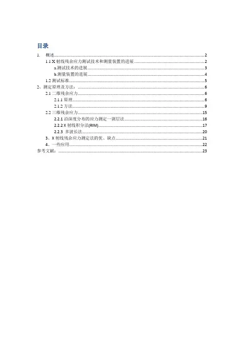
目录1.概述 (2)1.1 X射线残余应力测试技术和测量装置的进展 (2)a.测试技术的进展 (3)b.测量装置的进展 (4)1.2测试标准 (5)2、测定原理及方法: (6)2.1二维残余应力 (6)2.1.1原理 (6)2.1.2方法 (9)2.2三维残余应力 (15)2.2.1沿深度分布的应力测定一剥层法 (16)2.2.2 X射线积分法(RIM) (17)2.2.3 多波长法 (20)3、X射线残余应力测定法的优、缺点 (21)4、一些应用 (22)参考文献: (23)X射线衍射法残余应力测试原理、计算公式、测试方法的优缺点、目前主要应用领域。
1.概述X射线法是利用X射线入射到物质时的衍射现象测定残余应力的方法。
包括X射线照相法、X射线衍射仪法和X射线应力仪法。
1.1 X射线残余应力测试技术和测量装置的进展早在1936年,Glocker等就建立了关于x射线应力测定的理论。
但是当时由于使用照相法,需要用标准物质粉末涂敷在被测试样表面以标定试样至底片的距离,当试样经热处理或加工硬化谱线比较漫散时,标准谱线与待测谱线可能重叠,测量精度很低,因此,这种方法未受到重视,直到二十世纪四十年代末还有人认为淬火钢的应力测定是不可能的。
只有在使用衍射仪后,X射线应力测定才重新引起人们的重视,并在生产中日渐获得广泛应用。
美国SAE在巡回试样测定的基础上,于1960年对X射线应力测定技术进行了全面的讨论。
日本于1961年在材料学会下成立了X射线应力测定分会,并在1973年颁布了X射线应力测定标准方法。
a.测试技术的进展在二十世纪五十年代,X射线应力测定多采用0°~ 45°法(又称两次曝光法),这种方法在dψϕ与sin2ψ有较好的线性关系时误差不大,但当试件由于各种原因,dψϕ与sin2ψ偏离离直线关系时,0°~ 45°法就会产生很大误差。
为了解决这个问题,德国E.Macherauch在1961年提出了X射线应力测定的sin2ψ法,使x射线应力测定的实际应用向前迈进了一大步。
简述x射线衍射仪的光路布置
简述x射线衍射仪的光路布置英文回答:X-ray diffraction (XRD) is a non-destructive analytical technique used to determine the structure of a crystal. It is based on the principle that X-rays are scattered by atoms in a crystal in a regular manner, producing a diffraction pattern that can be used to determine the crystal's structure.The basic components of an XRD instrument are the X-ray source, the sample, the detector, and the data acquisition and analysis system. The X-ray source emits a beam of X-rays that is directed at the sample. The sample interacts with the X-ray beam and scatters the X-rays in a mannerthat is characteristic of the crystal's structure. The scattered X-rays are detected by the detector, and the data is collected and analyzed to determine the crystal's structure.The optical path of an XRD instrument is typically configured in one of two ways: the Bragg-Brentano geometry or the Debye-Scherrer geometry. In the Bragg-Brentano geometry, the X-ray beam is incident on the sample at a fixed angle, and the detector is moved to collect the scattered X-rays. In the Debye-Scherrer geometry, the X-ray beam is incident on the sample at a variable angle, and the detector is fixed.The choice of optical path depends on the specific application. The Bragg-Brentano geometry is typically used for single-crystal diffraction, while the Debye-Scherrer geometry is typically used for powder diffraction.中文回答:X射线衍射仪的光路布置主要有两种,布拉格-布伦塔诺几何和德拜-谢勒几何。
X射线荧光光谱法的应用和发展前景
准曲线的线性范围宽可达到3~5个数量级,尤其是使用激光做激发光源时效果更佳。
2 X 射线荧光光谱法的特点正常情况下,因其自身的特殊优势,X 射线荧光光谱法会作为物质成分分析的主要方式。
X 射线荧光光谱法不会因受到化学方面的影响而被左右,将X 射线荧光光谱法和原子发射光谱法进行比较,除氢元素之外,X 射线荧光光谱法可以比较容易的进行定量分析的矫正,可以克服基体吸收和增加效应,所以,谱线较为简单,受到的干扰也相对较少[3]。
从另一角度来讲,X 射线荧光光谱法不存在连续X 射线光谱,与原级X 射线发射光谱法相比,以散射线为主构成的拥有本底强度小的特征,谱峰和本底的对比表现出了较高的灵敏度,而且操作也相对简单,能够适应各种固态及液态样品的检测,可以更好的完成自动化的分析过程。
而且样品的击发过程中能够保持本性特征,强度测量有较好的再现性,更加适合无损分析的方式。
3 X 射线荧光光谱法的应用3.1 物质成分分析方法物质成分分析的方法多种多样,但只有定型和半定量分析符合野外和实际分析的条件,而且使用便携式X 射线荧光分析仪就可以达到规定的要求。
定量分析主要包含了实验校正法以及数学校正法,在以往的发展历程中,定量分析大多运用在构成比较简洁的物料方面的数学校正法,因其发展迟缓,实验校正法在市场中被大规模运用。
在后续的发展中,自动化仪器及计算机化程度帮助了X 射线荧光光谱分析方式发展,开始广泛使用数学校正法,该方法不仅能够分析大量不同的对象,还可以进行有效计算,更正不同原因对分析结果形成的影响。
0 引言X 射线荧光光谱法的发展历史最早可以追溯到1895年,德国物理学家威廉·康拉德·伦琴在当年的11月份第一次观察并发现出了X 射线,所以X 射线在世界许多国家被称为伦琴射线。
随后在1923年时,相关科研人员利用X 射线发现了一些较为新奇的化学元素,开启了X 光谱射线进行元素定量分析的趋势,因那时的资源条件有限,不能进行大规模运用,但是伴随科技的不断进步,在1948年时,美国就已经研发出了X 射线光谱仪,直至1965年作用于X 射线探测的仪器正式诞生,X 射线荧光光谱法也随着进行发展。
扫描X射线粉末衍射(XRPD)
扫描X射线粉末衍射(XRPD)弗雷德里克·范梅尔特(Frederik Vanmeert)1.分类扫描X射线粉末衍射(X-ray powder diffraction,XRPD)是一种化合物特异性成像技术,利用的是电磁频谱中的X射线。
属于非破坏式技术,可按分析样品类型分为侵入式检测(如小块颜料样品)和非侵入式检测(如整件艺术品)。
2.说明扫描XRPD是用X射线衍射对艺术品内部的结晶材料(颜料层和底料层的矿物和颜料粉)进行可视化处理。
当单色(即具有单一能量的)X射线与结晶材料相互作用时,每种晶体都会产生一种独特的衍射图形。
用已知矿物和化合物的数据库来比对这种“指纹”,就可以辨识各种晶体。
与XRF(X射线荧光)成像类似,扫描XRPD使用小型准直或聚焦X射线束对近似平面对象的表面进行光栅扫描,同时记录每个点的衍射图形。
经过高级数据分析,就可将各种晶体材料在物体内的分布可视化。
根据仪器的几何条件,可以只获取最表层信息(反射模式),也可以获取构成艺术品外观的所有层信息(透射模式)。
3.应用扫描XRPD是一种化合物特异性成像技术,用于显示(非)原始结晶材料在准平面艺术品上的分布。
这项技术主要用于无机化合物的鉴定和可视化,特别适合分辨含有相同元素的不同化合物,例如赤铁矿(Fe2O3)与针铁矿(α-FeOOH)、孔雀石(CuCO3·Cu(OH)2)、蓝铜矿(2CuCO3·Cu(OH)2)、水白铅矿(2PbCO3·Pb(OH)2)和白铅矿(PbCO3)。
艺术家为制造理想的视觉效果,会使用多色层叠压的技法,针对这种情况,可将微型颜料样品(通常<0.5mm)送至同步辐射设备,用非常窄的X射线束(约1 μm2)来研究颜料层的序列。
利用这种技术,除了可以深入了解艺术家的绘画技巧外,还可以揭示更多颜料层内部自发性劣化过程的信息。
此外,也可以通过研究晶体结构的具体变化来获得陶器和瓷器的生产过程相关信息。
x射线衍射成像技术发展详解
课程论文题目X射线衍射成像技术的原理以及最新发展与应用学院专业班级学生学号日月二〇年.摘要随着科技的发展,基于傅里叶光学的X射线衍射技术发展越来越先进,形成了X 射线衍射成像(X-ray diffraction imaging,XDI)和相干X射线衍射成像(coherent X-ray diffractive imaging,CXDI/CDI)等技术,它们广泛应用于材料、医学、生物、物理等领域,为人们探索微观世界的结构提供很好的工具。
本文主要论述了X 射线衍射的基本原理,并讲述了它们在不同应用中的最新发展,包括X射线衍射成像和相干X射线衍射成像的二维、三维成像等技术,同时简单的说明了它们在一些领域的应用。
关键词:X射线衍射;X射线衍射成像;相干X射线衍射成像1前言近几十年来,X射线衍射成像技术得到快速发展,它具有不损伤样品、无污染、快捷、测量精度高、能得到有关晶体完整性的大量信息等优点,大量的用于材料内部结构分析、生物分子探究、医学以及危险品扫描等领域。
近一个世纪以来,科学家们不断探索测定物质结构的方法,希望能够看到物质内部的原子是如何排列的。
而传统用的最多的方法是X射线晶体衍射分析的方法(XRD)能够实现物质的结构的测定,但它存在一定的局限性,然而在实际应用中,会受到很多的限制,为了更好的研究物质的结构,科学家们做了大量的工作,对X射线衍射技术进行改进升级,取得了一些最新的更成果,例如X射线衍射成像技术(X- ray diffraction imaging,XDI)、相干X射线衍射成像技术(coherent X-ray diffractive imaging,CXDI/CDI)等。
近年来,X射线衍射增强成像(X Ray Diffraction enhanced imaging,DEI)也发展迅速。
射线相位衬度成像是一种新型的X射线成像技术,通过记录射线穿过物体后相位的改变对物体进行成像,可以提供比传统的X射线吸收成像更高的图像衬度以及空间分辨力。
- 1、下载文档前请自行甄别文档内容的完整性,平台不提供额外的编辑、内容补充、找答案等附加服务。
- 2、"仅部分预览"的文档,不可在线预览部分如存在完整性等问题,可反馈申请退款(可完整预览的文档不适用该条件!)。
- 3、如文档侵犯您的权益,请联系客服反馈,我们会尽快为您处理(人工客服工作时间:9:00-18:30)。
Nuclear Instruments and Methods in Physics Research A 591(2008)14–18X-ray based methods for non-destructive testing and materialcharacterizationRandolf Hanke Ã,Theobald Fuchs,Norman UhlmannFraunhofer Entwicklungszentrum fu ¨r Ro ¨ntgentechnik,Dr.-Mack-Strasse 81,90762Fu ¨rth,GermanyAvailable online 20March 2008AbstractThe increasing complexity and miniaturization in the field of new materials as well as in micro-production requires in the same wayimprovements and technical advances in the field of micro-NDT to provide better quality data and more detailed knowledge about the internal structures of micro-components.Therefore,non-destructive methods like radioscopy,ultrasound,optical or thermal imaging increasingly gain in importance with respect to ongoing product and material development in the different phases like material characterization,production control or module reliability testing.Because of the manifold different application fields,i.e.,certain physical NDT methods applied to material inspection,characterization or reliability testing,this contribution will focus on the radioscopic-based methods related to their most important applications.Today,in modern industrial quality control,X-ray transmission is used in two different ways:Two-dimensional radioscopic transmission imaging (projection technique),usually applied to inline inspection tasks in application fields like lightweight material production,electronic component soldering or food production.Computed tomography (CT)for generation of three-dimensional data,representing spatial information and density distribution of objects.CT application fields are on the one hand the understanding of production process failure or component and module inspection (completeness)and on the other hand the dimensional measuring of hidden geometrical outlines (metrology).This paper demonstrates the methods including technical set-ups (X-ray source and detector),imaging and reconstruction results and the methods for high speed and high-resolution volume data generation and evaluation.r 2008Elsevier B.V.All rights reserved.PACS:07.79.7c;68.37.yz;81.70.Tx;87.57.Q À;87.59.Àe;87.59.B À;87.59.bd;87.59.bf Keywords:X-ray;Radioscopy;Micro-computed tomography;Image processing1.IntroductionRadioscopic inspection has become one of the most powerful tools in the field of non-destructive testing for industrial material inspection since the discovery of X-rays by Wilhelm Conrad Ro ntgen in the year 1895(Nobel Prize 1901).Already at this time,W.C.Ro ntgen had to face the same problems,which are still today regarded as majorchallenges with respect to advanced research and develop-ment for non-destructive testing:The high dynamic range of measured intensities caused by the exponential attenuation law for radiation in matter. The superposition of object structures along the radia-tion beam direction,caused by projective geometrical imaging (projection technique).Long exposure times,essential for a sufficient signal-to-noise ratio (SNR).Loss in contrast by diffuse background,generated by scattered radiation,which occurs during Compton/locate/nima0168-9002/$-see front matter r 2008Elsevier B.V.All rights reserved.doi:10.1016/j.nima.2008.03.016ÃCorresponding author.Tel.:+49911580617510;fax:+49911580617599.E-mail address:randolf.hanke@iis.fraunhofer.de (R.Hanke).interaction of photons with electrons of the outer atomic shell.The strong attenuation by metals compared to weak absorption of human skin,organs and tissue.2.X-ray beams—a short introduction2.1.X-ray generationX-rays are generated during acceleration of electrons, e.g.,in synchrotrons(synchrotron radiation)or by deceleration of electrons in solid-state materials(Brems-strahlung).Synchrotron radiation provides a highly brilliant beam (up to some1018photons/mrad s)especially capable for diffraction or for experiments which need coherent light (phase contrast method)but is unfortunately only available at some few research facilities in Europe.1On the other hand,X-ray tubes,which essentially create Bremsstrahlung,provide a considerably lower photonflux (some1012photons/mrad s),however are transportable and thus available in every laboratory.As this paper primarily will discuss industrial applications,hence the beam generation is focused on X-ray tubes.Depending on the focal spot size,macro-focus tubes (usually sealed tubes with spot sizes above100m m)or micro-focus tubes(open tubes with spot sizes down to 1m m)are commercially available.The principle of beam generation is shown in Fig.1(by courtesy of Viscom AG). Fig.1demonstrates the generation of Bremsstrahlung with a reflection target,i.e.,X-ray photons are emitted from a massive target anode usually used in a901angle to the direction of the impacting electron beam.As can be seen from thefigure,due to the target angle the size of the optical X-ray focus is different from the electron focus and also the characteristics of the Bremsstrahl spectrumchanges with the length of the absorption path due to varying target absorption of the generated X-rays(Heel effect).An alternative geometry is the transmission target solution,which means that electrons are impacting on a thin metal sheet target and the generated X-rays are emitted in the same direction as the electron beam.This solution offers of course a more homogeneous photon intensity characteristics and enables the realization of smaller focal spot sizes,however creates lower photon intensities compared to the reflection target due to a worse heat dissipation.2.2.X-ray detectionBesides the conventionalfilm radiography,digital imaging became more and more relevant in industrial radioscopy within the last20years.Today,most industrial digital detectors are still based on indirect conversion technology via scintillation effect(cf.Fig.2),which means integrating the detected photon intensity over all energies and converting this intensity into a local signal of visible light,which in turn is detected by silicon semiconductor detectors.Standard cameras are image intensifiers,a-Siflat panels or CMOS detectors,coated with scintillators(GdOx,CsI and others).Depending on the sensor pixel size,the coating thickness has to be adapted to achieve the best detective quantum efficiency(DQE)on the one hand[1]and to gain the optimal spatial resolution of the sensor on the other hand.Another way for X-ray photon detection is the direct conversion of the photons by semiconductors,which means,the impacting photons directly are converted into electron/hole pairs.Because of the progress of these alternative direct converting sensors within the last10 years,this technology may be expected to substitute or at least to partially replace the indirect converting technologyFig. 1.Generation of Bremsstrahlung by impact of electrons on a reflection target(courtesy of Viscom AG).Fig.2.Principle of direct(top)and indirect(bottom)detection of X-ray photons.1/als/synchrotron_sources.html.R.Hanke et al./Nuclear Instruments and Methods in Physics Research A591(2008)14–1815step by step within the next years.The major advantage is the much higher photon sensitivity(single photon counter) and the capability of resolving photon energy.Currently applied sensor semiconductor materials are CdTe, CdZnTe,Si,and GaAs.Compared to indirect converting detectors,today the bad economic conditions(price vs.active sensor area)may still be an advantage for the conventional integrating detectors.However,the significant physical advantages, e.g.,the capability of single photon counting for applica-tions like Nano CT with X-ray sources,having a very low photonflux and thus requiring long exposure times,will foster this method and hopefully provide competitive detector solutions even under economic aspects within the near future.3.Industrial radioscopic systemsAs already mentioned above,the main applications of industrial radioscopy can be differentiated by two-dimen-sional radiography and three-dimensional computed tomo-graphy(CT)(Fig.3).3.1.RadiographyThe main task in thisfield is the transfer of,e.g.,new detection technologies into the industrial production process for100%non-destructive testing, e.g.,of light alloy products,electronic components or even food[2,3]. Therefore,a radiographic system(Fig.4)has to provide X-ray images with highest achievable signal-to-noise ratio at simultaneously short exposure times.In addition, modern inspection systems have to allow for fully automated image processing and evaluation in order to become powerful and reliable tools for inline inspection (Fig.5).X-ray inspection is a method for visualizing a three-dimensional body in a two-dimensional plane,and hence, three-dimensional object details are superposed in a radio-graphic projection.These super-impositions may cause structures resembling defects in the X-ray images,so-called artifacts.Consequently,those artifacts as well as real structures have to be distinguished from real defects by image processing[4].puted tomographyThefield of computed tomography(CT)has attracted tremendous attention in the recent past[5,6].This is mainly due to three reasons:New detector technologiesHigh-performance computersHigh-performance X-ray tubesToday,in general,industrial CT can be differentiated into axial and planar CT depending on the geometry of the objects under inspection(cf.Fig.3).In particular,research activities are currently focused on Helical CT,High-Energy CT,Micro/Nano CT,Inline CT,and Robot CT.In this context,the success of system realization will strongly depend on the features of new detectors as a key component for CT!Regarding especially the Robot CT(Fig.6),which shall be applied for non-destructive X-ray laminographic inspection of large and bulky objects like aircraft fuselages orfins,large detectors with high sensitivity at low energiesFig.3.Different methods in industrialradioscopy.Fig.4.Schematic set-up for an industrial X-ray inspectionchain. Fig.5.Realization of an intelligent system for automated radioscopy (ISAR)for fully automated inspection of light alloy wheels.R.Hanke et al./Nuclear Instruments and Methods in Physics Research A591(2008)14–18 16are of utmost importance in order to provide quantitative means for testing carbonfiber reinforced components. Inline CT will need high-speed area array detectors, capable to provide images with a sufficiently high SNR and enabling readout frequencies of at least20frames per second,i.e.,exposure times below50ms.Nano CT systems are planned to be realized by enhancing an electron probe micro analyzer(EPMA)to a real nano focus X-ray source with focal spot sizes down to 100nm.The comparable low source intensity in combina-tion with a high demand on spatial resolution requires the use of highly sensitive and directly converting detectors with pixel sizes below10m m.In case of large parts,which show difficult geometries and aspect ratios,for instance rotor blades,Helical CT technique will be applied as a practical method to handle such objects.4.Applications in industrial material inspectionIn this chapter,some results for applications in different businessfields are presented.4.1.AerospaceFig.7shows two typical examples for the aerospacefield, representing the challenges in radiographic testing.In case of rotor blades,X-ray technology is applied to carbonfiber composites with low absorbing materials and low atomic numbers,whereas the turbine blades consist of strongly absorbing material(nickel-based alloys).Chal-lenges with these objects and materials are varying physical effects like radiation scattering or beam hardening.The development of CT systems,which are capable to detect, e.g.,pores or smallest delaminations within the composites or to measure small and hidden coolant boreholes of the turbine blades,currently is in progress.4.2.AutomotiveIn thisfield of business,the application of radioscopy is mainly focused on inline inspection accompanying the mass production of safety relevant components by advanced casting techniques.Thus,one major task will be the development and industrial realization of high-speed CT in order to generate and evaluate CT volume data,as demonstrated in Fig.8,within some10s for each part. 4.3.ElectronicsThe challenge in electronic component inspection is on the one hand the inapplicability of axial CT due to the geometry of,e.g.,printed circuit boards(PCB).On theFig.6.Schematic representation of a CT system with two communicating robots for X-ray source anddetector.Fig.7.Examples of radioscopy and CT inspection tasks in the aerospace businessfield.Fig.8.3D visualization of a cone beam CT reconstruction of an aluminum steering gear case;dark spots represent small blowholes.R.Hanke et al./Nuclear Instruments and Methods in Physics Research A591(2008)14–1817other hand,there is the need of highest resolution in therange of1m m and below to characterize the quality and reliability of wire bondings directly on chips and semi-conductor components.In order to check a PCB,laminography or digital tomosynthesis is applied to this inspection task.This means that only data from a limited range of projection angles are used for reconstruction.Even though there is a loss of information due to the incomplete set of data,Fig.9 demonstrates clearly the capability of this method to separate the different layers with a spacing of the single layers of approximately50m m.Nevertheless,due to the lack of information,a(negligible)contribution of blurring still is visible.Fig.10shows the sub-micro CT reconstruction of a CMOS chip.The size of one reconstructed volume element (voxel)in each of the three spatial dimensions is approximately900nm.The reconstruction was based on X-ray cone beam data,acquired during a single rotation of the object.AcknowledgmentsThis project was supported by the Freistaat Bayern and the European Community.References[1]K.Stierstorfer,M.Spahn,Self-normalizing method to measure thedetective quantum efficiency of a wide range of X-ray detectors,Med.Phys.(1999)26;Am.Assoc.Phys.Med.(1999)1312.[2]R.Hanke,T.Wenzel,Image processing for inline digital industrialradiology,J.Nondestruct.Eval.,Indian Soc.NDT(India)20/3(2001).[3]R.Hanke,T.Wenzel,U.Hassler,A new radioscopic system for postcast perfection,Foundry Trade J.176(3594)(2002).[4]T.Wenzel,R.Hanke,Texture analysis for classification of cast defectsin X-ray images,Second Workshop on NDT in Progress,Prag,2003.[5]R.Hanke,Microanalysis by volume computed tomography,in:G.I.T.Imaging&Microscopy,April2003,pp.40–43.[6]T.Fuchs,W.A.Kalender,Detectors for CT scanners,in:Alberto DelGuerra(Ed.),Ionizing Radiation Detectors for Medical Imaging, ISBN:981-238-674-2,2004,pp.125–147.Fig.9.Digital tomosynthesis applied to a multilayerPCB.Fig.10.Visualization of a cone beam CT reconstruction of a smallfraction(left)of a CMOS memory chip.R.Hanke et al./Nuclear Instruments and Methods in Physics Research A591(2008)14–18 18。
