ZG193控制器技术规格书..
2. TF9600系列控制器产品说明书(V2.1)——封面
JB- QBZL-TF9610火灾报警控制器(联动型) JB- TGZL-TF9620火灾报警控制器(联动型) JB- TTZL-TF9620火灾报警控制器(联动型)
产品使用说明书
V2.1
辽宁同方安全技术有限公司
2010.04
第一章 概 述 (1)
1.1 适用范围 (1)
1.2 系统简介 (1)
1.3 产品特点 (1)
1.4 命名规则 (2)
第二章 系统特性 (3)
2.1 工作环境 (3)
2.2 主要参数 (3)
2.3 主要性能 (3)
2.4 负载能力 (3)
第三章 系统结构与配置 (4)
3.1 外型 (4)
3.2 控制器面板说明 (5)
3.3 内部结构 (5)
第四章 安装与调试 (9)
4.1 开箱检查 (9)
4.2 开机检查 (9)
4.3 外部设备检查 (9)
4.4 场地要求 (9)
4.5 布线要求 (9)
4.6 接线和设置 (10)
4.7 调试 (10)
4.8 试运行 (10)
第五章 常用说明指导 (10)
5.1 用户使用说明 (10)
5.2 系统管理说明 (10)
5.3 系统维护说明 (10)
第六章 贮存与运输 (11)
6.1 贮存要求 (11)
6.2 运输要求 (11)
第七章售后服务 (11)
7.1 质保期 (11)
7.2 售后联系方式 (11)
附录控制器接线说明附录控制器内部主要器件接线图说明 (12)。
高压脉冲轨道电路技术规格书汇总

神朔铁路2013整治整修物资设备设备名称:高压脉冲轨道电路设备技术规格书中铁第五勘察设计院集团有限公司二○一三年九月目录目录1.概述2.技术要求3.高压脉冲轨道电路规格4.标准化5.系统质保期、维护及维修6.需要提供的设备7.备品、备件8.测试验收9.技术资料10.技术培训11.技术指导及技术支援12.标记、包装、运输、贮存13.附则附件1:技术建议书应包含的内容附件2:报价书应包含的内容附件3:物资采购清单1.概述1.1适用范围本规格书适用于神朔铁路2013整治整修高压脉冲轨道电路设备的构成、制造、试验、开通、验收的有关规定,并作为卖方编制技术建议书的依据。
1.2招标范围招标范围为神朔铁路2013整治整修府谷站、孤山川站、新城川站、神木北站、神木北机务段5个站高压脉冲轨道电路设备。
1.3工程有关情况说明1.3.1车站信号联锁设备的设置情况为:招标范围内各站均采用硬件安全冗余型计算机联锁系统。
25Hz相敏轨道电路,站内正线及到发线采用ZPW-2000型电码化设备。
2技术要求2.1总则高压脉冲轨道电路设备应符合相关的国家标准、行业标准及有关规定。
2.2工作环境2.2.1室外温度范围为-40o C~+70o C,室内温度范围为-5o C~+40。
2.2.2室外相对湿度不大于95%(温度+25o C),室内相对湿度不大于85%(温度+25o C)。
2.2.3大气压力为70.1kPa~106kPa(相对海拔高度3000m以下)。
2.2.4周围无腐蚀和引起爆炸危险的有害气体。
2.2.5振动室内设备(不含继电器):在振动频率5Hz~200Hz时,应能承受加速度为5m/s2的正弦稳态振动。
室外设备:在振动频率5Hz~200Hz时,应能承受加速度为20m/s2。
2.3系统组成不对称高压脉冲轨道电路由不对称高压脉冲发送设备、传输设备、不对称高压脉冲通道、不对称高压脉冲接收设备组成。
3高压脉冲轨道电路技术规格1.高压脉冲轨道电路应满足铁道部《高压不对称脉冲轨道电路暂行技术条件》的要求。
钢支座技术规格书

九、其它
1.大型桥梁需采用特殊设计的支座时,除满足本技术规格书外,还应满足设计图纸及有关标准、规范的要求。当本技术规格书与设计图纸及有关标准、规范不一致时,应以设计图纸及有关标准、规范为准。
2.支座应预留调高条件(螺栓加长,加垫板等措施)。
3.依据的主要标准、规范
(1)《新建时速300~350公里客运专线铁路设计暂行规定(上、下)》
(2)《铁路桥涵钢筋混凝土和预应力混凝土结构设计规范》(TB10002.3-2005)
(3)《铁路桥梁钢结构设计规范》(TB10002.2-2005)
(4)《铁路桥梁铸钢支座技术条件》(TB/T1853-1995)
2.一般规定
2.1除非本技术规格书另有规定,在引用的标准或规定发生分歧时,应按以下顺序优先考虑:
(1)本技术规格书;
(2)本技术规格书所依据的标准、规范;
(3)中华人民共和国相关国家标准、行业标准及规范;
(4)其它国家官方、团体或协会颁布的标准、规范。
2.2本技术规格书中引用的标准或规范,如在实施期间颁布新的版本,实施时是否采用新版本的规定,由建设单位、支座设计单位和支座制造厂共同协商,并报铁道部确定。
(1)铸造厂应提出合理的铸造工艺,铸造质量由支座制造厂负全责,外委铸造厂(如有)负连带责任。
(2)铸钢件热处理应符合TB/T1853-1995《铁路桥梁铸钢支座》中第5.2.2条的要求。
(3)铸钢件清砂后,按《铸件尺寸公差与机械加工余量》(GB/T 6414-1999)进行尺寸与形状检查。
1.2机械加工
20000ZX
球型支座
0.1g<Ag≤0.2g
控制器产品基础知识手册
---------------------------------------------------------------最新资料推荐------------------------------------------------------控制器产品基础知识手册控制器产品基础知识目录一、控制器知识 ........................................................ ............................................... 3 (一)概念 ........................................................ . (3)(二)专业名词 ........................................................ ........................................... 3 (三)功能解释 ........................................................ ............................................... 3 (四)常规限流 ........................................................ ............................................... 5 二、公司控制器命名规则 ........................................................ ............................... 5 三、标准型 ........................................................ . (6)四、节能型 ........................................................1/ 14 (7)五、正弦波控制型 ........................................................ ....................................... 8 六、双模型 ........................................................ ................................................... 9 七、控制器与电机匹配性问题 ........................................................ ................. 10 公司控制器产品目前包括四大系列普及型、节能型、正弦波控制型、双模型,每一个系列的功能特征、市场定位等都有所不同。
(仅供参考)米亚基控制器(CT-110C中文版)
外部输入输出信号 ················································································································ 2
时序图···································································································································· 操作方法 --------------------------------------------------------------------------------------------------------
最大电流的设定 ···················································································································· 6
电流校正的方法 ···················································································································· 电池和保险丝的更换 -----------------------------------------------------------------------------------------
● 打开捆包箱后,请确认本装置是否在运输过程中受到破损、附属品是否配备齐全。 万一发现装置受损或附属品不全,请立即与销售商或营业担当联系。
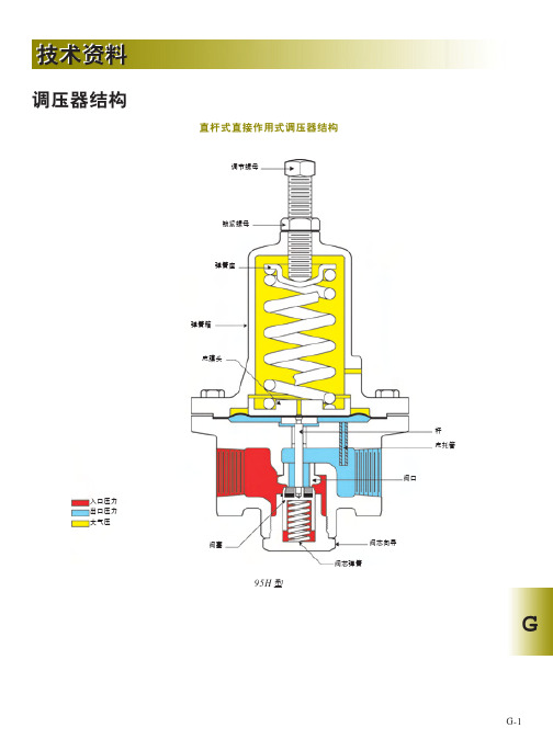
调压器技术资料
G
终端连接形式 一般来说,对于确定的调压器尺寸,以下的终端连 接形式宜于采用: ● NPT 螺钉连接或管座焊接:2 英寸(DN50)以及
更小尺寸。 ● 平焊接:1- 英寸(DN25)及更大尺寸。 ● 法兰焊接:1- 英寸(DN25)及更大尺寸。 注意:并非所有的终端连接形式对于任何调压器均 适用。
控制线路 对于压力记录来说,控制线路由下游的减压调压器 和上游的背压调压器连接而成。典型的大型自力式 调压器具有外置式控制线路,而小型的自力式调压 器具有内置式压力记录装置来取代控制线路。大多 数指挥器作用式调压器都具有外置式控制线路,但 在使用具体的调压器时,必须予以确定。
所需材料 调压器的结构材料通常取决于其实际的应用情况。 标准材料包括: ●铝 ● 锻铁或球墨铸铁 ●钢 ● 铜或黄铜 ● 不锈钢
处理过程中所需要的特殊材料可能影响到可使用的 调压器类型。如:供氧设备需要特殊的材料,并要 求调压器内没有油或润滑油。
需使用关闭控制型调压器的实际情况包括以下几中: ● 燃烧器控制。在燃烧起中,燃料 / 空气的比值是影
G
G-5
技术资料
调压器介绍
调压器 调压器用于维持所需要的减小后的出口压力,同时 提供为确保下游流量所需的流体流动。调压器所要 维持的压力就是它的出口压力设定值。
真空泵
被限制的 真空空间
真空断路器色标
入口压力 控制压力(真空) 大气压
大气压或实际压力
被控制的 真空空间
入口压力 出口压力 负载压力 大气压
调压器的类型 这一节中介绍了不同型号的调压器、所有的调压器 都可以被划分成以下两种类型:
1. 直接作用式(也称作自控型) 2. 指挥器控制式
自力式调压器 自力式调压器广泛应用于出口压力小于1 psig(0.069 bar)的情况,可作为更高出口压力的第一步粗略的 减压。尽管更精细的控制可根据具体的应用需求达 到,但它通常可产生的压力变化为 10%~20%。
DAB 193 中央气动泵说明书
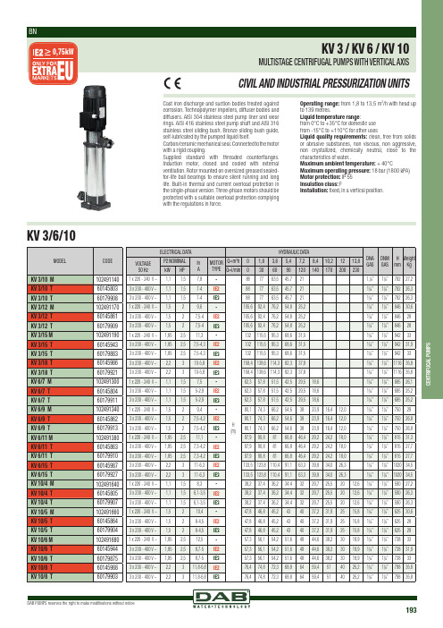
DAB PUMPS reserves the right to make modifications without notice193C E N T R I F U G A L P U M P SCast iron discharge and suction bodies treated against corrosion. Technopolymer impellers, diffuser bodies and diffusers. AISI 304 stainless steel pump liner and wear rings. AISI 416 stainless steel pump shaft and AISI 316 stainless steel sliding bush. Bronze sliding bush guide, self-lubricated by the pumped liquid itself.Carbon/ceramic m echanical s eal. C onnected t o t he m otor with a rigid coupling.Supplied standard with threaded counterflanges. Induction motor, closed and cooled with external ventilation. Rotor mounted on oversized greased sealed-for-life ball bearings to ensure silent running and long life. Built-in thermal and current overload protection in the single-phase version. Three-phase motors should be protected with a suitable overload protection complying with the regulations in force.Operating range: from 1,8 to 13,5 m3/h with head up to 139 metres.Liquid temperature range:from 0°C to +35°C for domestic usefrom -15°C to +110°C for other usesLiquid quality requirements: clean, free from solids or abrasive substances, non viscous, non aggressive, non crystallized, chemically neutral, close to the characteristics of water..Maximum ambient temperature: + 40°C Maximum operating pressure: 18 bar (1800 kPA) Motor protection: IP 55Insulation class: FInstallation: fixed, in a vertical position.KV 3/6/10。
Belimo ZG-JSL 和 ZG-JSLA 旋钮阀控制器技术数据表说明书

ZG-JSL, ZG-JSLADefault/ConfigurationApplicationOperationFor Use with Belimo Rotary ActuatorsTechnical dataFunctional dataMounting Position 90° to 180°Safety dataAmbient temperature -22...122°F [-30...50°C]Storage temperature-40...176°F [-40...80°C]MaterialsHousing material galvanized steel Stemsteel Frame, plate, base galanized steel BearingGF Delrin Suitable actuatorsNon-SpringAMB(X)GMB(X)NMB(X)Electronic fail-safeNKQB(X)* ZG-121 adapter must be used with EF. ** GM/GK not for use with 1/2" shafts. *** K6-1 clamp must be used with LF. For close-off pressure reference Select Pro or Retrofit Technical Documentation.For close-off pressure reference Select Pro or retrofit technical documentation.Product featuresThe ZG-JSL linkage can also be configured by moving the anti-rotation plate 90° for space-savingapplications. See mounting configurations below. The ZG-JSLA will have a factory mounted actuator on the linkage in the vertical position only.The ZG-JSL jackshaft linkage is designed to easily attach to any part of a jackshaft and allow easyinstallation of select Belimo actuators. The unique open ended design and clamp insert allows the ZG-JSL to be used with any jackshaft from ½” to ¾” in diameter. Removal of the insert will allow the linkage to attach to a maximum shaft diameter of 1.05”. Changing the antirotation plate will allow various actuators to be mounted.The ¾” diameter built-in steel shaft allows direct coupling to the Belimo series actuators in the chart below. There is a torque reduction when using the ZG-JSL linkage. Verify application requirements before use.Flow/Mounting detailsDimensionsZG-JSL, ZG-JSLA Dimensional drawingsAFX24-MFT Modulating, Spring Return, 24 V, Multi-FunctionTechnology®Proportional, Spring Return, 24 V Multi-FunctionTechnology, Torque min. 180 in-lb, Control 2 to 10VDC (DEFAULT), Feedback 2 to 10 VDC (DEFAULT)Technical dataElectrical data Nominal voltage AC/DC 24 VNominal voltage frequency50/60 HzPower consumption in operation7.5 WPower consumption in rest position 3 WTransformer sizing10 VA (class 2 power source)Electrical Connection18 GA appliance or plenum cables, 3 ft [1 m], 10 ft [3m] or 16ft [5 m], with or without 1/2" conduitconnectorOverload Protection electronic throughout 0...95° rotationElectrical Protection actuators are double insulatedFunctional data Torque motor180 in-lb [20 Nm]Operating range Y 2...10 VOperating range Y note 4...20 mA w/ ZG-R01 (500 Ω, 1/4 W resistor)Input Impedance100 kΩ for 2...10 V (0.1 mA), 500 Ω for 4...20 mA,1500 Ω for PWM, On/Off and Floating pointOperating range Y variable Start point 0.5...30 VEnd point 2.5...32 VOptions positioning signal variable (VDC, PWM, on/off, floating point)Position feedback U 2...10 VPosition feedback U note Max. 0.5 mAPosition feedback U variable VDC variableDirection of motion motor selectable with switch 0/1Direction of motion fail-safe reversible with cw/ccw mountingManual override 5 mm hex crank (3/16" Allen), suppliedAngle of rotation95°, adjustable with mechanical end stop, 35...95°Angle of rotation note adjustable with mechanical end stop, 35...95°Running Time (Motor)default 150 s, variable 70...220 sRunning time motor variable70...220 sRunning time fail-safe<20 s @ -4...122°F [-20...50°C], <60 s @ -22°F [-30°C]Angle of rotation adaptation off (default)Override control MIN (minimum position) = 0%MID (intermediate position) = 50%MAX (maximum position) = 100%Noise level, motor40 dB(A)Noise level, fail-safe62 dB(A)Shaft Diameter1/2...1.05" round, centers on 1/2" and 3/4" withinsert, 1.05" without insertPosition indication MechanicalSafety data Degree of protection IEC/EN IP54AFX24-MFTDefault/ConfigurationApplicationOperation Typical specification Degree of protection NEMA/UL NEMA 2 UL Enclosure Type 2Agency Listing cULus acc. to UL60730-1A/-2-14, CAN/CSAE60730-1:02, CE acc. to 2014/30/EU and 2014/35/EU; Listed to UL 2043 - suitable for use in airplenums per Section 300.22(c) of the NEC andSection 602.2 of the IMCQuality Standard ISO 9001Ambient temperature-22...122°F [-30...50°C]Storage temperature-40...176°F [-40...80°C]Ambient humidity max. 95% r.H., non-condensingServicing maintenance-freeWeight Weight 4.1 lb [1.9 kg]Materials Housing material Galvanized steel and plastic housingProduct featuresDefault parameters for 2 to 10 VDC applications of the AF..-MFT actuator are assigned duringmanufacturing. If required, custom versions of the actuator can be ordered. The parameters are variableand can be changed by three means: Factory pre-set or custom configuration, set by the customer usingPC-Tool software or the handheld ZTH US.For fail-safe, modulating control of dampers in HVAC systems. Actuator sizing should be done inaccordance with the damper manufacturer’s specifications. A feedback signal is provided for positionindication for master-slave applications. Two AF's can be piggybacked for torque loads to max. 360 in-lb.Minimum 3/4" diameter shaft. OR Maximum of three AF's can be piggybacked for torque loads to max.432 in-lb. Minimum 3/4" diameter shaft. Master-Slave wiring for either configuration. Actuators must bemechanically linked.When not mechanically linked, actuators must be wired in parallel.The AF..24-MFT actuator provides 95° of rotation and is provided with a graduated position indicatorshowing 0° to 95°. The actuator will synchronize the 0° mechanical stop or the physical damper or valvemechanical stop and use this point for its zero position during normal control operations. A uniquemanual override allows the setting of any actuator position within its 95° of rotation with no powerapplied. This mechanism can be released physically by the use of a crank supplied with the actuator. Whenpower is applied the manual override is released and the actuator drives toward the fail-safe position. Theactuator uses a brushless DC motor which is controlled by an Application Specific Integrated Circuit (ASIC)and a microprocessor. The microprocessor provides the intelligence to the ASIC to provide a constantrotation rate and to know the actuators's exact position. The ASIC monitors and controls the brushless DCmotor's rotation and provides a Digital Rotation Sensing (DRS) function to prevent damage to the actuatorin a stall condition. The position feedback signal is generated without the need for mechanical feedbackpotentiometers using DRS. The actuator may be stalled anywhere in its normal rotation without the needof mechanical end switches. The AF..24-MFT is mounted directly to control shafts up to 1.05" diameter bymeans of its universal clamp and anti-rotation bracket. A crank arm and several mounting brackets areavailable for damper applications where the actuator cannot be direct coupled to the damper shaft. Thespring return system provides minimum specified torque to the application during a power interruption.The AF..24-MFT actuator is shipped at 5° (5° from full fail-safe) to provide automatic compression againstdamper gaskets for tight shut-off.Spring return control damper actuators shall be direct coupled type which require no crank arm andlinkage and be capable of direct mounting to a jackshaft up to a 1.05” diameter. The actuator mustprovide modulating damper control in response to a 2 to 10 VDC or, with the addition of a 500Ω resistor, a4 to 20 mA control input from an electronic controller or positioner. The actuators must be designed sothat they may be used for either clockwise or counter clockwise fail-safe operation. Actuators shall use abrushless DC motor controlled by a microprocessor and be protected from overload at all angles ofrotation. Run time shall be constant, and independent of torque. A 2 to 10 VDC feedback signal shall beprovided for position feedback or master slave applications. Actuators with auxiliary switches must beconstructed to meet the requirements for Double Insulation so an electrical ground is not required tomeet agency listings. Actuators shall be cULus listed and have a 5 year warranty, and be manufacturedunder ISO 9001 International Quality Control Standards. Actuators shall be as manufactured by Belimo.AFX24-MFT Factory settings Default parameters for 2 to 10 VDC applications of the AF..-MFT actuator are assigned duringmanufacturing. If required, custom versions of the actuator can be ordered. The parameters are variableand can be changed by three means: Factory pre-set or custom configuration, set by the customer usingPC-Tool software or the handheld ZTH US.AccessoriesGateways Description TypeGateway MP to BACnet MS/TP UK24BACGateway MP to LonWorks UK24LONGateway MP to Modbus RTU UK24MOD Electrical accessories Description TypeDC Voltage Input Rescaling Module IRM-100Belimo PC-Tool, Software for adjustments and diagnostics MFT-PAuxiliary switch, mercury-free P475Auxiliary switch, mercury-free P475-1Signal Siumlator, Power supply AC 230 V PS-100Convert Pulse Width Modulated Signal to a 2...10 V Signal for Belimo ProportionalActuatorsPTA-250Positioner for wall mounting SGA24Positioner for front-panel mounting SGF24Cable Conduit Connector 1/2"TF-CC USGateway MP to BACnet MS/TP UK24BACGateway MP to LonWorks UK24LONGateway MP to Modbus RTU UK24MODResistor, 500 Ω, 1/4" wire resistor with 6" pigtail wires ZG-R01Resistor Kit, 50% voltage divider ZG-R02Mounting plate for SGF.ZG-SGFTransformer, AC 120 V to AC 24 V, 40 VA ZG-X40Connection cable 16 ft [5 m], A: RJ11 6/4 ZTH EU, B: free wire end for connection to MP/PP terminal ZK2-GENService Tool, with ZIP-USB function, for parametrisable and communicativeBelimo actuators, VAV controller and HVAC performance devicesZTH US Mechanical accessories Description TypeAnti-rotation bracket, for AF / NF AF-PShaft extension 240 mm Ø20 mm for damper shaft Ø 8...22.7 mm AV8-25End stop indicator IND-AFBShaft clamp reversible, for central mounting, for damper shafts Ø12.7 / 19.0 /25.4 mmK7-2Ball joint suitable for damper crank arm KH8 / KH10KG10ABall joint suitable for damper crank arm KH8KG8Actuator arm, for 3/4" shafts, clamping range Ø10...22 mm, Slot width 8.2 mm KH-AFBDamper crank arm Slot width 8.2 mm, clamping range Ø14...25 mm KH10Damper crank arm Slot width 8.2 mm, for Ø1.05"KH12Damper crank arm Slot width 8.2 mm, clamping range Ø10...18 mm KH8Push rod for KG10A ball joint (36” L, 3/8” diameter).SH10Push rod for KG6 & KG8 ball joints (36” L, 5/16” diameter).SH8Wrench 8 mm and 10 mm TOOL-06Retrofit clip Z-AFBase plate extension Z-SF17" Mounting Bracket for AF,NF,GM,AM,SM ZG-100Mounting Bracket: AF,NF,LF,GM,AM,NM,SM ZG-101Dual actuator mounting bracket.ZG-102Mounting Bracket: ZS-260 Right Angle ZG-109Linkage kit ZG-110Mounting bracketfor AF / NFZG-118Jackshaft mounting bracket.ZG-120Mounting kit for linkage operation for flat and side installation ZG-AFBMounting kit for foot mount installation ZG-AFB118Damper clip for damper blade, 3.5” width.ZG-DC1Damper clip for damper blade, 6” width.ZG-DC2AFX24-MFT1" diameter jackshaft adaptor (11" L).ZG-JSA-11-5/16" diameter jackshaft adaptor (12" L).ZG-JSA-21.05" diameter jackshaft adaptor (12" L).ZG-JSA-3Weather shield 13x8x6" [330x203x152 mm] (LxWxH)ZS-100Base Plate, for ZS-100ZS-101Weather shield 16x8-3/8x4" [406x213x102 mm] (LxWxH)ZS-150Explosion Proof Housing 16x10x6.435" [406x254x164 mm] (LxWxH), UL and CSA, Class I, Zone 1&2, Groups B, C, D, (NEMA 7), Class III, Hazardous (classified) LocationsZS-260Weather shield 17-1/4x8-3/4x5-1/2" [438x222x140 mm] (LxWxH), NEMA 4X, with mounting bracketsZS-300Weather shield 17-1/4x8-3/4x5-1/2" [438x222x140 mm] (LxWxH), NEMA 4X, with mounting brackets ZS-300-5Shaft extension 1/2"ZS-300-C1Shaft extension 3/4"ZS-300-C2Shaft extension 1"ZS-300-C3Service toolsDescriptionType Connection cable 10 ft [3 m], A: RJ11 6/4 ZTH EU, B: 3-pin Weidmüller and supply connectionZK4-GEN Service Tool, with ZIP-USB function, for parametrisable and communicative Belimo actuators, VAV controller and HVAC performance devicesZTH USElectrical installationWarning! Live Electrical Components!During installation, testing, servicing and troubleshooting of this product, it may be necessary to work with live electrical components. Have a qualified licensed electrician or other individual who has been properly trained in handling live electrical components perform these tasks. Failure to follow all electricalsafety precautions when exposed to live electrical components could result in death or serious injury.Meets cULus requirements without the need of an electrical ground connection.Actuators with appliance cables are numbered.Provide overload protection and disconnect as required.Actuators may also be powered by 24 VDC.Only connect common to negative (-) leg of control circuits.A 500 Ω resistor (ZG-R01) converts the 4...20 mA control signal to 2...10 V.Control signal may be pulsed from either the Hot (Source) or Common (Sink) 24 V line.For triac sink the Common connection from the actuator must be connected to the Hot connection of the controller. Position feedback cannot be used with a triac sink controller; the actuator internal commonreference is not compatible.IN4004 or IN4007 diode. (IN4007 supplied, Belimo part number 40155).Actuators may be controlled in parallel when not mechanically linked. Current draw and input impedancemust be observed.Master-Slave wiring required for piggy-back applications when mechanically linked. Feedback fromMaster to control input(s) of Slave(s).On/Off Floating PointAFX24-MFTVDC/mA Control PWM ControlOverride Control Master - SlaveDimensionsDimensional drawings。
- 1、下载文档前请自行甄别文档内容的完整性,平台不提供额外的编辑、内容补充、找答案等附加服务。
- 2、"仅部分预览"的文档,不可在线预览部分如存在完整性等问题,可反馈申请退款(可完整预览的文档不适用该条件!)。
- 3、如文档侵犯您的权益,请联系客服反馈,我们会尽快为您处理(人工客服工作时间:9:00-18:30)。
ZG193家用热泵热水机控制器技术规格书编制:周俊审核:批准:浙江中广电器有限公司一、概述本控制器为家用热泵热水器专用控制器,有五路温度传感器(水箱温度、排气温度、外机温度、环境温度、回气温度),四路控制输出(压缩机、四通阀、风机高,风机低),两路告警信号输入(高压、低压保护),一路电流检测信号输入,一路电子膨胀阀输出。
要求控制器在调整参数及后期升级软件时,只需更换显示板。
二、主要功能1.温度显示和自动控制制热功能;2.掉电记忆功能(开/关机及参数设置);3.压缩机开机延时保护;4.自动化霜控制;5.排气温度保护;6.高、低压力告警保护功能;7.电流检测及过流保护功能;8.内置时钟,可分时段运行;9.故障代码显示功能;10.电子膨胀阀控制;11.单、双风速控制;12.加氟、收氟功能;13.辅助电加热控制;(预留)14.远程控制功能;(预留)15.一键还原功能;16.485通讯。
三、控制器性能要求1.使用条件a.运行电压: AC220V±20%b.运行环境温度: -20~+60℃c.储存温度: -30~+85℃d.湿度要求: 30~95%RH 防潮2.参数要求a.温度显示范围: -50~150℃b.温度设定范围: 0~100℃,可限定设置范围c.温度控制及测试精度:±1℃3.控制器符合a.GB 4706.1-2005《家用和类似用途电器的安全第一部分:通用要求》b.GB 4706.32-2012《家用和类似用途电器的安全热泵﹑空调器和除湿机的特殊要求》c.GB/T 23137-2008《家用和类似用途热泵热水器》d.GB 4343.2-2009《家用电器、电动工具和类似器具的电磁兼容要求第2部分:抗扰度》e.GB/T 4588.3-2002 《印制板的设计和使用》四、控制面板说明1.控制面板图2.操作控制面板上电后,显示此控制面板的型号、程序版本,再显示画面如图1。
a.显示功能控制器平时显示的是水箱水温,按“”显示排气温度,按“”显示外机温度,同时按“”和“”显示电流。
b.开关机按“”键,可开机或关机,开机状态根据工作情况显示“制热”、“保温”或“化霜”,关机状态显示“关机”,关闭全部输出。
无论开机状态还是关机状态,总是显示当前时间和水温。
c.设置水温按“”键,进入机组停机温度设定状态,显示“设置温度”(如图3),用“”或“”键改变设定值(“”键增1︒C ,“”键减1︒C,按住不放超过0.5秒则快速增减)。
再按一次“”键可按同样方法设置机组启动温度(如图4),完成后再按“”键退出设置状态(如图5)。
控制器在检测到水温低于“启动温度”时开始制热,到水温高于“设置温度”时停止制热,将温度控制在“启动温度”和“设置温度”之间。
温度启停上下限的调整范围可以限定,请参见高级设置(参数F13和F14)。
d.设置工作模式按“”键,可以在“自动模式”和“经济模式”两种模式之间切换。
“自动模式”下根据设定的温度控制热泵加热。
“经济模式”只在预定的三个开机时段内加热,其它时间不加热。
e.设置时间按“”键,时钟的小时部分闪烁,用“”或“”键可以调整小时数,调整好后再按“”键,按同样的方法调整分钟数,再按“”键则退出时间设置状态f.设置经济模式工作时段长按“”键2秒,进入加热时段设置状态(如图6)。
时段1:此时“定时开1”的时钟在闪烁,按“”或“”键改变数值,再按“”键,“定时开1”的分钟在闪烁,此时可以按“”或“”键改变数值,再按“”键,进入“定时关1”的时间设置(如图7),设置方法同“定时开1”。
时段2:再按“”键就进入“定时开2”的设置状态,根据时段1开关的方法设置。
时段3:同时段1、时段2的方法设置。
三个时间段设置完后,再按“”键退出经济模式工作时段设置状态,最多可以设置三个加热时段,如果不需要这么多时段,可以将不需要时段的起始时间和结束时间都设为“00:00”。
另外如果某个时段的结束时间早于起始时间,则认为这个结束时间是次日。
例如某时段设为“22:00”到“03:30”,则认为是晚上22点到次日3点30分。
g.高级设置长按“”键5秒,进入参数设置状态,如果设置了口令(参数F80),会显示“PAS”字样提示输入口令,用“”和“”键输入口令,如果口令正确,会进入参数设置状态,这时显示器上显示“Fxx”,其中xx是两位数字,表示参数代码(如图8)。
用“”或“”键可选择参数代码,选择一个代码后按“”键则显示该代码对应的参数值(如图9),这时再用“”或“”键即可对参数值进行设置,设置完成后再按“”键,回到显示参数代码状态(如图10)。
i.告警处理说明:1、探头发生故障时,对应的温度显示“OPE”表示开路,“SHr”表示短路。
可按“ ”或“ ”键观察各个探头的温度显示。
2、“告警代码”出现在温度显示位置,和温度交替显示。
3、“自动恢复”指的是当异常情况消失后,自动退出告警状态。
4、“人工恢复”指的是当异常情况消失后,控制器仍锁定在告警状态,需要人工关机再开机才能恢复。
五、控制功能描述1.主板a.输入信号:◆5路温度传感器:R25℃=5K;B25℃/50℃=3470K;◆2个光耦隔离开关量;◆2个互感电路采集点(预留一个)。
◆显示板b.输出信号:压缩机继电器:220V±20% 30A电加热继电器:220V±20% 30A (预留)四通阀继电器:220V±20% 5A高风继电器:220V±20% 5A低风继电器:220V±20% 5A电子膨胀阀c.插件、插片要求:插件按颜色匹配,插片规格6.3*0.8。
2.温度控制温度控制根据“设置温度”和“启动温度”两个参数进行,假设“设置温度”为60︒C,“启动温度”为50︒C,则当水温低于50︒C时启动制热,到水温达到60︒C时停止制热,将温度控制在50︒C --60︒C之间。
3.压缩机保护控制器内有一个“压缩机停机计时器”,当压缩机停机时开始计时,下一次启动前首先检查这个计时器,如果已满三分钟则立即启动压缩机,如果不满三分钟则等满三分钟再启动;另外控制器刚通电的三分钟之内也不会启动压缩机。
(*注:压缩机开机延时保护时间是可调的(参数F21),以上假定设置成三分钟)环境温度≤F23时,停压缩机,开电加热,到设定温度。
屏蔽此参数时,该功能无效4.分时段运行控制器内部有实时钟,能够准确计时。
控制器在“经济模式”下,除根据水温确定是否需要加热外,还要看当前时间是否在设定的运行时段内,如果不在时段内,则不管水温高低都不加热。
5.自动化霜化霜过程只在制热状态进行,即在非制热状态不会启动化霜a.进入化霜条件:在制热过程中,不断监测外机温度,根据外机处在连续低温状态的时间来判断是否需要化霜。
即当外机温度低于“化霜启动温度”时化霜计时器开始计时,当计时值达到“化霜启动时间”则启动化霜;系统满足条件则进入化霜。
液晶显示化霜符号。
b.退出化霜条件:①外机温度升到“化霜结束温度”;②化霜时间超过了“最大化霜时间”;系统满足上面 条件的任意一个,则退出化霜。
4.3 化霜四通阀模式:6.低压告警保护低压告警可设置成常开、常闭或禁用(参数F50)。
“常开”表示正常情况下信号是断开的,闭合则产生告警,“常闭”则反之,“禁用”表示不使用告警信号。
压缩机刚启动4分钟和化霜时及化霜结束后的4分钟之内不检测低压告警信号。
当发生低压告警信号时,系统停止工作,待低压告警信号恢复正常时,可以自动恢复到正常工作状态。
但是如果一小时内连续出现三次低压告警,则系统锁定在告警状态,需要人工关机后才能恢复。
这个次数和时间是可以设置的,详见参数F51和F52。
例: F51=1,F52=60,可以理解为在60分钟内,出现第一次故障时允许自动恢复,在60分钟内出现第二次故障则系统锁定,需要人工恢复。
7.高压告警保护高压告警可设置成常开、常闭或禁用(参数F54)。
“常开”表示正常情况下信号是断开的,闭合则产生告警,“常闭”则反之,“禁用”表示不使用告警信号。
当发生高压告警信号时,系统停止工作,待高压告警信号恢复正常时,可以自动恢复到正常工作状态。
但是如果一小时内连续出现三次高压告警,则系统锁定在告警状态,需要人工关机后才能恢复。
这个次数和时间是可以设置的,详见参数F55和F56。
8.排气温度保护当控制器检测到排气温度过高时,进入告警状态,停止制热。
这个温度点是可设置的(参数F58和F59)。
假设F58=110︒C(温度),F59=30︒C(回差),则排气温度高于110︒C(F58)时进入告警状态,停止制热,排气温度低于80︒C(F58-F59)时恢复。
当排气温度在1小时内出现3次故障时,锁定排气温度告警。
F58=OFF时,无排气温度保护功能,也不会出现排气温度探头故障告警。
9.风机控制当F40=0时(单风速):A、当T环<F41(环温)时:高速风输出;B、当T环≥F41时:T排气≤90℃时,高速风输出;T排气>F42(110℃可调)时,停风机;当F40=1时(双风速):A、当T环<F41时:高速风运行;B、当T环≥F41时:T排气≤90℃时,高速风运行;T排气>F42-10时,低速风运行;T排气≥F42时,停风机;注:温度之间保存原态。
当环温或者排气出现故障(或被屏蔽)时,当压缩机开启时风机保持高风输出(化霜除外)。
当环境温度传感器出现故障(或被屏蔽)时,以排气温度为准控制风机;当排气传感器故障时,当压缩机开启时风机保持高风输出(化霜除外)10.电加热(预留)满足①或者同时满足②③或③④或③⑤,电加热工作,①机组连续运行F22小时(包括化霜)且T水箱<F11②T环≤F15③T水箱<F12④机组锁定故障,不启动,⑤(按住M键4秒)满足①②条件之一,则退出① T水箱≥F11电加热启动后5秒,检查电加热电流<F48时停电加热,显示故障A71。
在参数设置中,“电子膨胀阀控制方式选择”可选用[自动]、[手动]或[环境],1)[自动]的以过热度T1(T回气-T盘管)为基准来调节电子膨胀阀的开度。
在参数设置中,“过热度设置”F73是回气温度T回气与盘管温度T盘管的差值过热度T1所要求数值,这个是机器在正常工作中膨胀阀调节的依据。
①使用开度范围(100步-480步)(三花电子膨胀阀);②上电后,电子膨胀阀全关后再开到最大开度(480步),压机开启后1分钟后然后按环境温度开到适合开度;③压机关闭开到最大开度(480步);④化霜开到最大开度(480步);⑤电子膨胀阀调节频率为30秒/次;⑥若盘管或回气损坏,维持原来值,待制热结束或关机,开到最大开度(480步),后由2项决定;⑦排气温度大于“电子膨胀阀排气设置”F76时,电子膨胀阀每次强制加大5步,当排气温度小于85度时,按正常过热度调节。