CXB3_U4_LEAD IN
AUTOSAR_SWS_XCP
Document Title Specification of Module XCP Document Owner AUTOSARDocument Responsibility AUTOSARDocument Identification No 412Document Classification StandardDocument Version 2.0.0Document Status FinalPart of Release 4.0Revision 3Document Change HistoryDate Version Changed by Change Description12.12.2011 2.0.0 AUTOSARAdministration ∙Added parameters for Event Channel and Timestamp configuration∙Added possibility to calculate memory consumption for ODT (DAQ & STIM) ∙ Restructuring configurationparameters for static & dynamic ODT ∙Added support for deactivation of transmission capabilities11.10.2010 1.1.0 AUTOSARAdministration ∙Add chapter 7.8 (Version check), RTE limitation, OS Counter Ref∙Remove InstanceID and known limitation (OS)07.12.2009 1.0.0 AUTOSARAdministration∙ Initial ReleaseDisclaimerThis specification and the material contained in it, as released by AUTOSAR, is for the purpose of information only. AUTOSAR and the companies that have contributed to it shall not be liable for any use of the specification.The material contained in this specification is protected by copyright and other types of Intellectual Property Rights. The commercial exploitation of the material contained in this specification requires a license to such Intellectual Property Rights.This specification may be utilized or reproduced without any modification, in any form or by any means, for informational purposes only.For any other purpose, no part of the specification may be utilized or reproduced, in any form or by any means, without permission in writing from the publisher.The AUTOSAR specifications have been developed for automotive applications only. They have neither been developed, nor tested for non-automotive applications.The word AUTOSAR and the AUTOSAR logo are registered trademarks.Advice for usersAUTOSAR specifications may contain exemplary items (exemplary reference models, "use cases", and/or references to exemplary technical solutions, devices, processes or software).Any such exemplary items are contained in the specifications for illustration purposes only, and they themselves are not part of the AUTOSAR Standard. Neither their presence in such specifications, nor any later documentation of AUTOSAR conformance of products actually implementing such exemplary items, imply that intellectual property rights covering such exemplary items are licensed under the same rules as applicable to the AUTOSAR Standard.Table of Contents1Introduction and functional overview (5)2Acronyms and abbreviations (6)3Related documentation (7)3.1Input documents (7)3.1.1Related standards and norms (8)4Constraints and assumptions (9)4.1Limitations (9)4.2Applicability to car domains (9)5Dependencies to other modules (10)5.1AUTOSAR RTE (BSW Scheduler) (10)5.2AUTOSAR FlexRay Interface (10)5.3AUTOSAR CAN Interface (10)5.4AUTOSAR SocketAdaptor (10)5.5AUTOSAR RTE (10)5.6AUTOSAR OS (10)5.7AUTOSAR Diagnostic Event Manager (10)5.8AUTOSAR Development Error Tracer (10)5.9File structure (11)5.9.1Code file structure (11)5.9.2Header file structure (11)6Requirements traceability (13)6.1General Requirements on Basic Software Modules (13)6.2Requirements on the XCP Basic Software Module (15)7Functional specification (16)7.1XCP on CAN (18)7.2XCP on FlexRay (19)7.3XCP on Ethernet (21)7.4Requirements on Debugging (22)7.4.1General Requirements (22)7.5Error classification (23)7.6Error detection (24)7.7Error notification (24)7.8Version checking (24)8API specification (26)8.1Imported types (26)8.2Type definitions (26)8.2.1Xcp_ConfigType (26)8.2.2Xcp_Transmission Mode Type (26)8.3Function definitions (27)8.3.1Xcp_Init (27)8.3.2Xcp_GetVersionInfo (28)8.4Call-back notifications (29)8.4.1Xcp_<module>RxIndication (29)8.4.2Xcp_<module>TxConfirmation (30)8.4.3Xcp_<Lo>TriggerTransmit (30)8.4.4Xcp_SetTransmissionMode (31)8.5Scheduled functions (32)8.5.1Xcp_MainFunction (32)8.6Expected Interfaces (32)8.6.1Mandatory Interfaces (32)8.6.2Optional Interfaces (33)8.6.3Configurable interfaces (33)9Sequence diagrams (35)9.1XCP on FlexRay (35)9.1.1Xcp on FlexRay Transmit (35)9.1.2Xcp on FlexRay Receive Indication (35)9.2XCP on CAN (36)9.2.1Xcp on CAN Transmit (36)9.2.2Xcp on CAN Transmit Confirmation (36)9.2.3Xcp on CAN Receive Indication (37)9.3XCP on Ethernet (38)9.3.1Xcp on Ethernet Receive Indication (38)10Configuration specification (39)10.1How to read this chapter (39)10.1.1Configuration and configuration parameters (39)10.1.2Variants (39)10.1.3Containers (40)10.1.4Specification template for configuration parameters (40)10.2Containers and configuration parameters (40)10.2.1Variants (41)10.2.2Xcp (42)10.2.3XcpGeneral (42)10.2.4XcpConfig (51)10.2.5XcpDaqList (52)10.2.6XcpDto (54)10.2.7XcpOdt (54)10.2.8XcpOdtEntry (55)10.2.9XcpDemEventParameterRefs (56)10.2.10XcpEventChannel (59)10.2.11XcpPdu (61)10.2.12XcpRxPdu (62)10.2.13XcpTxPdu (63)10.3Published Information (64)11Not applicable requirements (65)1 Introduction and functional overviewThis specification specifies the functionality, API and the configuration of the AUTOSAR Basic Software module XCPXCP is a protocol description (ASAM standard) between a master (tool) and a slave (device), which provides the following basic features:- Synchronous data acquisition (measurement)- Synchronous data stimulation (for rapid prototyping)- Online memory calibration (read / write access)- Calibration data page initialization and switching- Flash Programming for ECU development purposes- Every feature is optional and the access can be restricted- Various communications busses are supportedXCP was designed according to the following principles:- Minimal Slave resource consumption (RAM, ROM, runtime)- Efficient communication- Simple Slave implementation2 Acronyms and abbreviationsAcronym: Description:AUTOSAR AUT omotive O pen S ystem AR chitectureA2L File Extension for an ASAM 2MC Language FileASAM A ssociation for S tandardization of A utomation and M easuringSystemsBSW B asic S oft w areCAN C ontroller A rea N etworkCanIf CAN I nter f aceCTO C ommand T ransfer O bjectDAQ D ata A c Q uisition, Data AcQuisition PacketDTO D ata T ransfer O bjectECU E lectronic C ontrol U nitFrIf F lex R ay I nter f aceHIS H ersteller I nitiative S oftwareLPDU Data Link Layer PDUMCD M easurement C alibration and D iagnosticsMISRA M otor I ndustry S oftware R eliability A ssociationODT O bject D escriptor T ablePDU P rotocol D ata U nitRAM R andom A ccess M emoryROM R ead O nly M emorySchM Sch edule M anagerSVN S ub v ersio nSRS S oftware R equirements S pecificationSTIM DataStim ulation packetSW S oft w areSWS S oft w are S pecificationTCP/IP T ransfer C ontrol P rotocol /I nternet P rotocolTS T ime S tampUDP/IP U ser D atagram P rotocol /I nternet P rotocolURL U niform R esource L ocatorProtocolCalibrationXCP UniversalXML E x tensible M arkup L anguageISR I nterrupt S ervice R outineDEM D iagnostic E vent M anager (AUTOSAR BSW module)DET D evelopment E rror T racer (AUTOSAR BSW module)3 Related documentation3.1 Input documents[0] Basic Software Module Description TemplateAUTOSAR_TPS_BSWModuleDescriptionTemplate.pdf [1] List of Basic Software ModulesAUTOSAR_TR_BSWModuleList.pdf[2] AUTOSAR Layered Software ArchitectureAUTOSAR_EXP_LayeredSoftwareArchitecture.pdf [3] General Requirements on Basic Software ModulesAUTOSAR_SRS_BSWGeneral.pdf[4] Specification of RTE (BSW Scheduler)AUTOSAR_SWS_RTE.pdf[5] Specification of ECU ConfigurationAUTOSAR_TPS_ECUConfiguration[6] Specification of Memory MappingAUTOSAR_SWS_MemoryMapping.pdf[7] Specification of FlexRay InterfaceAUTOSAR_SWS_FlexRayInterface.pdf[8] Specification of CAN InterfaceAUTOSAR_SWS_CANInterface[9] Specification of Socket AdaptorAUTOSAR_SWS_SocketAdaptor[10] Requirements on XCP ModuleAUTOSAR_SRS_XCP.pdf[11] AUTOSAR OS Specification:AUTOSAR_SWS_OS3.1.1 Related standards and norms[12] ASAM XCP – The Universal Measurement and Calibration Protocol/index.php?option=com_content&task=view&id=136&Itemid= 18[13] ASAM XCP – Transport Layer Specification XCP on CAN/index.php?option=com_content&task=view&id=136&Itemid= 18[14] ASAM XCP – Transport Layer Specification XCP on Ethernet/index.php?option=com_content&task=view&id=136&Itemid= 18[15] ASAM XCP – Transport Layer Specification XCP on FlexRay/index.php?option=com_content&task=view&id=136&Itemid= 184 Constraints and assumptions4.1 LimitationsThe following XCP features are currently out of scope:- The XCP feature “Flash Programming for ECU development purposes” is currently out of AUTOSAR scope!- The SET_DAQ_ID command according to the XCP CAN Transport Layer Specification is not part of the AUTOSAE XCP module”- Currently, the AUTOSAR RTE does not offer APIs for direct communication with XCP- For further details concerning the supported feature set, please refer to [12] Please note:For the communications bus LIN, no ASAM XCP is specified.4.2 Applicability to car domainsn/a5 Dependencies to other modulesThis section describes the relations to other modules and files within the AUTOSAR basic software architecture. It contains brief descriptions of configuration information and services, which are required by the XCP module from other modules.5.1 AUTOSAR RTE (BSW Scheduler)The BSW Scheduler calls the main functions of the Xcp, which are necessary for the cyclic processes of the Xcp.5.2 AUTOSAR FlexRay InterfaceThe FlexRay Interface is used to transmit and receive XCP PDUs via FlexRay.5.3 AUTOSAR CAN InterfaceThe CAN Interface is used to transmit and receive XCP PDUs via CAN.5.4 AUTOSAR SocketAdaptorThe SocketAdaptor is used to transmit and receive XCP PDUs via Ethernet.5.5 AUTOSAR RTEThe RTE is used for copying calibration parameters from ROM/FLASH to RAM andto use the double pointered method5.6 AUTOSAR OSIn order to be able to use the time stamped feature of XCP, an AUTOSAR OS Counter is used.5.7 AUTOSAR Diagnostic Event ManagerIn order to be able to report production errors, the XCP has to have access to the Diagnostic Event Manager.5.8 AUTOSAR Development Error TracerIn order to be able to report development errors, the XCP has to have access to the error hook of the Development Error Tracer.5.9 File structure5.9.1 Code file structure[Xcp501]⌈The code file structure shall not be defined within this specification completely. At this point it shall be pointed out that the code-file structure shall include the following files named:- Xcp.c – general source code file of the module XCP- Xcp_Cfg.c – for pre-compile time configurable parameters- Xcp_Lcfg.c – for link time configurable parameters and- Xcp_PBcfg.c – for post build time configurable parameters.⌋(BSW00380, BSW00419, BSW00383, BSW00346, BSW158)These files shall contain all link time and post-build time configurable parameters.[Xcp500]⌈The module XCP shall access the location of the API of all used modules for pre-compile time configuration by either using of external declaration in includes of the used modules’ public header files <x>.h or by the code file Xcp_Cfg.c.⌋()5.9.2 Header file structure[Xcp502] ⌈Figure 5-1: XCP Header File Structure⌋(BSW00381, BSW00412, BSW00409,BSW00301)The XCP module shall include the Dem.h file. By this inclusion, the APIs to report errors as well as the required Event Id symbols are included. This specification defines the name of the Event Id symbols, which are provided by XML to the DEM configuration tool. The DEM configuration tool assigns ECU dependent values to the Event Id symbols and publishes the symbols in Dem_IntErrId.h.[Xcp503] ⌈All files related to the XCP module shall follow the naming conventionXcp[_<description>].<extension>⌋(BSW00300)[Xcp505]⌈The implementation of the XCP module shall provide the header file Xcp.h, which is the main module interface file. It shall contain all types and function prototypes required by the XCP module’s environment.⌋(BSW00302)[Xcp506]⌈The implementation of the XCP on CAN module shall provide the header file XcpOnCan_Cfg.h that shall contain the pre-compile-time configuration parameters.⌋()[Xcp507] ⌈The implementation of the XCP on FlexRay module shall provide the header file XcpOnFr_Cfg.h that shall contain the pre-compile-time configuration parameters.⌋()[Xcp508] ⌈The implementation of the XCP on Ethernet module shall provide the header file XcpOnEth_Cfg.h that shall contain the pre-compile-time configuration parameters.⌋()[Xcp509] ⌈The module shall include the Dem.h file.⌋()By this inclusion, the APIs to report errors as well as the required Event Id symbols are included. This specification defines the name of the Event Id symbols which are provided by XML to the DEM configuration tool. The DEM configuration tool assigns ECU dependent values to the Event Id symbols and publishes the symbols in Dem_IntErrId.h.6 Requirements traceability6.1 General Requirements on Basic Software ModulesRequirement Satisfied by BSW00344 Reference to link-time configuration Xcp741 BSW00404 Reference to post build time configuration Xcp742 BSW00405 Reference to multiple configuration sets Xcp803 BSW00345 Pre-compile-time configuration Xcp742 BSW159 Tool-based configuration Xcp102 BSW167 Static configuration checking Xcp103Xcp104Xcp105 BSW171 Configurability of optional functionality n/aBSW170 Data for reconfiguration of AUTOSAR SW-Components n/aBSW00380 Separate C-Files for configuration parameters Xcp501 BSW00419 Separate C-Files for pre-compile time configuration parameters Xcp501 BSW00381 Separate configuration header file for pre-compile time parameters Xcp502 BSW00412 Separate H-File for configuration parameters Xcp502 BSW00383 List dependencies of configuration files Xcp501 BSW00384 List dependencies to other modules Chapter 5 BSW00387 Specify the configuration class of callback function n/aBSW00388 Introduce containers Xcp101 BSW00389 Containers shall have names Chapter 10.2 BSW00390 Parameter content shall be unique within the module Chapter 10.2 BSW00391 Parameter shall have unique names Chapter 10.2 BSW00392 Parameters shall have a type Chapter 10.2 BSW00393 Parameters shall have a range Chapter 10.2 BSW00394 Specify the scope of the parameters Chapter 10.2 BSW00395 List the required parameters (per parameter) Chapter 10.2 BSW00396 Configuration classes Chapter 10.2 BSW00397 Pre-compile-time parameters Chapter 10.2 BSW00398 Link-time parameters Chapter 10.2 BSW00399 Loadable Post-build time parameters Chapter 10.2 BSW00400 Selectable Post-build time parameters Chapter 10.2 BSW00402 Published information Xcp807 BSW00375 Notification of wake-up reason n/aBSW101 Initialization interface Xcp803 BSW00416 Sequence of Initialization n/aBSW00406 Check module initialization Xcp811 BSW168 Diagnostic Interface of SW components n/aBSW00407 Function to read out published parameters Xcp807n/a BSW00423 Usage of SW-C template to describe BSW modules with AUTOSARInterfacesBSW00424 BSW main processing function task allocation Xcp823 BSW00425 Trigger conditions for schedulable objects n/aBSW00426 Exclusive areas in BSW modules n/aBSW00427 ISR description for BSW modules n/aBSW00428 Execution order dependencies of main processing functions n/aBSW00429 Restricted BSW OS functionality access Chapter 5.6 BSW00431 The BSW Scheduler module implements task bodies n/an/a BSW00432 Modules should have separate main processing functions forread/receive and write/transmit data pathBSW00433 Calling of main processing functions Xcp823 BSW00434 The Schedule Module shall provide an API for exclusive areas n/aBSW00336 Shutdown interface n/aBSW00337 Classification of errors Errorclassification BSW00338 Detection and Reporting of development errors Chapter 7.6Chapter 7.7 BSW00369 Do not return development error codes via API Chapter BSW00339 Reporting of production relevant error status Chapter BSW00417 Reporting of Error Events by Non-Basic Software n/aBSW00323 API parameter checking Chapter 8.3 BSW004 Version check Xcp749BSW00409 Header files for production code error IDs Xcp502BSW00385 List possible error notifications Chapter 7.5 BSW00386 Configuration for detecting an error Xcp754BSW161 Microcontroller abstraction n/aBSW162 ECU layout abstraction n/aBSW005 No hard coded horizontal interfaces within MCAL n/aBSW00415 User dependent include files n/aBSW164 Implementation of interrupt service routines n/aBSW00325 Runtime of interrupt service routines n/aBSW00326 Transition from ISRs to OS tasks n/aBSW00342 Usage of source code and object code Chapter 10.2.1 BSW00343 Specification and configuration of time Chapter 10.2 BSW160 Human-readable configuration data Xcp744BSW007 HIS MISRA C Xcp745BSW00300 Module naming convention Xcp503BSW00413 Accessing instances of BSW modules n/aBSW00347 Naming separation of different instances of BSW drivers n/aBSW00305 Self-defined data types naming convention Chapter 8.2 BSW00307 Global variables naming convention Xcp800BSW00310 API naming convention Xcp800BSW00373 Main processing function naming convention Xcp823BSW00327 Error values naming convention Xcp763BSW00335 Status values naming convention n/aBSW00350 Development error detection keyword Xcp753BSW00408 Configuration parameter naming convention Xcp800BSW00410 Compiler switches shall have defined values n/aBSW00411 Get version info keyword Xcp807Xcp808Xcp809Xcp810BSW00346 Basic set of module files Xcp501BSW158 Separation of configuration from implementation Xcp501BSW00314 Separation of interrupt frames and service routines n/aBSW00370 Separation of callback interface from API n/aBSW00348 Standard type header Chapter 5.9 BSW00353 Platform specific type header Chapter 5.9 BSW00361 Compiler specific language extension header Chapter 5.9 BSW00301 Limit imported information Xcp502BSW00302 Limit exported information Xcp505BSW00328 Avoid duplication of code n/aBSW00312 Shared code shall be reentrant n/aBSW006 Platform independency n/aBSW00357 Standard API return type Chapter 8.3 BSW00377 Module specific API return types n/aBSW00304 AUTOSAR integer data types Chapter 8.3 BSW00355 Do not redefine AUTOSAR integer data types Chapter 8.3 BSW00378 AUTOSAR boolean type Chapter 8.3 BSW00306 Avoid direct use of compiler and platform specific keywords n/aBSW00308 Definition of global data Xcp760BSW00309 Global data with read-only constraint n/aBSW00371 Do not pass function pointers via API n/aBSW00358 Return type of init() functions Xcp803BSW00414 Parameter of init function Xcp803BSW00376 Return type and parameters of main processing functions Chapter 8.5 BSW00359 Return type of callback functions Chapter 8.4 BSW00360 Parameters of callback functions n/aBSW00329 Avoidance of generic interfaces n/aBSW00330 Usage of macros / inline functions instead of functions n/aBSW00331 Separation of error and status values n/aBSW009 Module User Documentation n/aBSW00401 Documentation of multiple instances of configuration parameters n/aBSW172 Compatibility and documentation of scheduling strategy n/aBSW010 Memory resource documentation n/aBSW00333 Documentation of callback function context n/aBSW00374 Module vendor identification Xcp807BSW00379 Module identification Xcp807BSW003 Version identification Xcp807BSW00318 Format of module version numbers Xcp807BSW00321 Enumeration of module version numbers n/aBSW00341 Microcontroller compatibility documentation n/aBSW00334 Provision of XML file Xcp751BSW00435 Header File Structure for the Basic Software Scheduler Xcp747BSW00436 Module Header File Structure for the Memory Mapping Xcp7486.2 Requirements on the XCP Basic Software ModuleRequirement Satisfied by BSW429001 Location of XCP within the architecture Xcp701BSW429002 API usage Xcp712, Xcp714,Xcp720, Xcp734 BSW429003 Unique PDU-ID Xcp702BSW429004 XCP Specification Version 1.1 Xcp703BSW429005 XCP on CAN Xcp713BSW429006 XCP on FlexRay Xcp719BSW429007 XCP on Ethernet Xcp733BSW429008 A2L Support n/aBSW429009 Synchronous data acquisition Xcp705BSW429010 Synchronous data stimulation Xcp707BSW429011 Block communication mode Xcp711BSW429012 Interleaved communication mode Xcp710BSW429013 Dynamic data transfer configuration Xcp706BSW429014 Timestamped Data transfer Xcp709BSW429015 Bypassing Xcp761BSW429016 Seed & Key Xcp766BSW429017 XCP Initialization Xcp8037 Functional specificationThe specification of the module XCP shall define all parameters and interfaces, which are required to use the ASAM XCP protocol specification within an AUTOSAR environment.Description:Black arrows: Data Path (Signals/Pdus)Orange arrows: Control Path (FlexRay Interface)[Xcp701]⌈The AUTOSAR XCP Module be located above the bus specific Interfaces in case of FlexRay and Can. In case of Ethernet, the AUTOSAR XCP module shall be located above the Socket Adaptor.⌋(BSW429001)[Xcp702]⌈For transmitting and receiving of XCP messages, unique PDU-IDs shall be used. ⌋(BSW429003)[Xcp703]⌈The AUTOSAR XCP Module shall support the ASAM XCP Specification Version 1.1.⌋(BSW429004)[Xcp705]⌈The AUTOSAR XCP Module shall support the basic feature “Synchronous data acquisition (measurement) “. Please refer to [13]⌋(BSW429009)[Xcp706]⌈The AUTOSAR XCP Module shall support the feature “Dynamic DAQ Configuration”. according to [13]⌋(BSW429013)[Xcp707]⌈The AUTOSAR XCP Module shall support the basic feature “Synchronous data stimulation” according to [13]⌋(BSW429010)[Xcp708]⌈The AUTOSAR XCP Module shall support the basic feature “Online memory calibration (read / write access) “, according to [13]⌋()[Xcp709]⌈The AUTOSAR XCP Module shall support the feature “Timestamped Data Transfer“, according to [13]⌋(BSW429014)[XCP 768]⌈The ECU local time shall be derived from the AUTOSAR OS.⌋()[Xcp711]⌈The AUTOSAR XCP Module shall support the feature “Block communication mode“, according to [13]⌋(BSW42911)[Xcp761]⌈The AUTOSAR XCP Module shall support the feature “Bypassing“, according to [13]⌋(BSW429015)[Xcp766]⌈The AUTOSAR XCP Module shall support the feature “Seed & Key” according to [13]⌋(BSW429016)[Xcp712]⌈For sending and receiving of calibration data, the sending and receiving APIs specified within the AUTOSAR BSW Bus Interfaces (FlexRay Interface, CAN Interface, TCP/IP Socket Adaptor) shall be used. Please refer to chapter 7.1, 7.2 and 7.3.⌋(BSW429002)7.1 XCP on CAN[Xcp713]⌈The AUTOSAR XCP Module shall support the CAN communications bus according to [14]⌋(BSW429005)[Xcp714]⌈XCP data sent and received via CAN, the PDUs have to be transmitted and received using the transmitting and receive APIs provided by the AUTOSAR CAN Interface, according to [9]⌋(BSW429002)[Xcp715]⌈For sending and receiving XCP data via CAN, at least two different CAN identifiers have to be configured to be used by XCP.⌋()[Xcp716]⌈Performance information shall be exchanged between the XCP master and XCP slave using the parameters according to [14]⌋()[Xcp718]⌈The XCP Module shall support the GET_SLAVE_ID command according to [14]⌋()7.2 XCP on FlexRay[Xcp719]⌈The AUTOSAR XCP Module shall support the FlexRay communications bus according to [16]⌋(BSW429006)[Xcp720]⌈XCP data sent and received via FlexRay, the PDUs have to be transmitted and received using the transmit and receive APIs provided by the AUTOSAR FlexRay Interface according to [8].⌋(BSW429002)[Xcp721]⌈All XCP on FlexRay LPDUs always are event driven. Please refer to Chapter 1.1.2 “FlexRay Frame Type” of [16]⌋()[Xcp722]⌈The hardware buffers (of the FlexRay Communication Controller) XCP uses for data transmission and reception are assigned exclusively to the XCP module.⌋()Note:This restriction prevents disturbances of ongoing FlexRay communication.[Xcp723]⌈The usage of FlexRay Communication Controller’s hardware buffers shall be configured by the corresponding parameters according to [16]⌋()[Xcp724]⌈The FlexRay PDU length used by the AUTOSAR XCP module shall be set using the corresponding parameters according to [16]⌋()[Xcp725]⌈LPDU_IDs which shall be routed to the AUTOSAR XCP module (using the AUTOSAR Bus Interface) have to be defined by the system designer. ⌋()[Xcp726]⌈The ASAM MCD 2MC description file (i.e. A2L file) describes to which extent the XCP-dedicated buffers of a specific slave can be configured for XCP communication.⌋()[Xcp728]⌈The XCP master gets the information about the XCP dedicated FlexRay Communication Controller buffers from the ASAM MCD 2MC description file. ⌋()[Xcp729]⌈Limitations due to the usage of multiple XCP slaves on the FlexRay communications bus shall be taken into consideration by the system designer. Please refer to [16].⌋()[Xcp730]⌈Depending upon the requirements on sequencing correctness, alignment and net data throughput, different header types are possible. Please refer to Chapter 1.4.1 ”Header” of [16]⌋()[Xcp731]⌈For XCP on FlexRay, the Tail consists of a Control Field containing optional FILL bytes according to [16].⌋()[Xcp732]⌈The AUTOSAR XCP module shall be able to pack multiple XCP messages into one FlexRay Frame according to [16].⌋()7.3 XCP on Ethernet[Xcp733]⌈The AUTOSAR XCP Module shall support the Ethernet communications bus according to [15]⌋(BSW429007)[Xcp734]⌈XCP data sent and received via Ethernet, the PDUs have to be transmitted and received using the transmitting and receive APIs provided by the AUTOSAR Socket Adaptor according to [10].⌋(BSW429002)[Xcp735]⌈The AUTOSAR XCP slave connected by Ethernet and TCP/IP or UDP/IP is addressed by its IP Address and Port number.⌋()[Xcp736]⌈The AUTOSAR XCP slave only accepts one connection at the time. ⌋()[Xcp737]⌈If the socket is closed while in XCP connected state, the slave device will perform an XCP disconnect, which means that all data acquisition will be stopped.⌋()[Xcp738]⌈The addressing scheme is defined according to [15]⌋().[Xcp739]⌈The header and tail of an XCP on Ethernet message have to be set according to [15]⌋()[Xcp740]⌈The upper performance limit depends on the protocol stack of the host system. The corresponding parameters defined according to [15] have to be set.⌋()[Xcp710]⌈The AUTOSAR XCP Module shall support the feature “Interleaved communication mode“, according to according to [15]⌋(BSW429012)7.4 Requirements on Debugging[Xcp760]⌈Each variable that shall be accessible by AUTOSAR Debugging, shall bedefined as global variable.⌋(BSW00308)[Xcp759]⌈All type definitions of variables which shall be debugged, shall be accessible by the header file Xcp.h⌋()[Xcp762]⌈The declaration of variables in the header file shall be such that it is possible to calculate the size of the variables by C-"sizeof".⌋()[Xcp765]⌈Variables available for debugging shall be described in the respectiveBasic Software Module Description.⌋()[Xcp764]⌈The internal XCP states shall be available for debugging.⌋()In general, it is not necessary/intended for AUTOSAR debugging, that SWS documents define specific variables.7.4.1 General Requirements[Xcp741]⌈Link-time and post-build-time configuration data shall be implemented as read-only data structures. Link-time configuration data shall be immediately referenced by the implementation, the start-address of post-build-time configuration data shall be passed during module initialization⌋(BSW00344)[Xcp742]⌈The XCP module shall support pre-compile time, link-time and post-build-time configuration.⌋(BSW00404, BSW00345)[Xcp744]⌈The description of the configuration and initialization data itself is not part of this specification but very implementation specific. The generated configuration data should be “human-readable”.⌋(BSW160)。
CAXA协同管理使用指南-设计人员

CAXA协同管理使用指南一、用户登录i.i快捷图标说明CAXA协同管理安装完毕后会在桌面上显示两个图标CAXA协同管理图文档(客户端),启动此程序进入PDM主界面,文档的查询、浏览、出入库、编辑等日常工作的操作都在这个界面。
工作流程的任务箱,启动后进入工作流程的任务界面,所有任务的提醒、接收、审批、签名等操作可以直接进入。
1.2登陆启动图文档界面后弹出登陆界面,输入用户名与密码,默认密码为Wd123456 。
点击设置可以输入PDM服务器所在的地址,服务器端口默认不能改动,可以在软件安装时设置,后续登陆则无需修改。
注意:项目组内部测试的服务器(地址为192.168.1.154 )并不是后续正式使用的服务器, 正式上线时可能会涉及到修改服务器地址信息。
登陆后进入主程序,主界面的右下角显示当前的用户,如下:mi万德用户使用自己的姓名登陆系统,进入系统后首先修改自己的密码,方法如下图:主界面上分为菜单区、快捷命令区、文档树、树结构及查询区、对象属性区。
这些区域舀C :AXA 协辰勰2033 •茅文槿•改件夹•]请各用户妥善保管自己人密码,若有遗忘,需向系统管理员申请将密码重置。
PDM 界面使用2.1主界面进入PDM 主界面,首先认识一下 PDM 主界面的各个部分知A 廿颐*叫5爲棄躯!v H 快捷畚令ixT -I > ^RTRL*5 F <Jt«H-a E Ki 档工" 卜用5 E MHP E WIBftt EM-4 严P3・ □ PWM曹沱 Q HriaE D IWR1W C Z ■« a B*sr*a ZMJ * t Sri-B" HTMP Ha zMti< t IS-+M H IBEHI n B*i*i t: cs ■电-c ari-£fk j StM氏a 土 :咖t 自^H :QSX=:a讥财 旳魁 軸 辺也 ■HWLE Kk文档樹产甜结构树 査询区«■=**憫卑4FWSI-CJ宣rwim文档属性区Hd■・《jn : r-1. frB ItT r人员管理空陲改密冯如(VJ交档樹导出人员权眼抿羔4代理広)序改晋爲i 青紐旧密码:名输 请输入篩密码创豊人靑诵认詡密玛卵:白作凉詈瑾肋 工具辅① 窗口帕 赳助00文档冀型文井狀态文件类塑 交件犬■■.門宠鮎-1「|通用兗档 I 匕 BOM 1 IT 标進化文档 + Q 旬装文件 -i-Q 采艰玳 卄EH 更改单 ^■■Q 工住件 卄曰工装交件 士匕逆瞬酬范 ± Q 技术通知 I. □ RAMS 文件 3-E 杠势书 + a 设计文件 卄已営息交流单 鼻曰盾更整改交件 1+卜|j?~| i>il30dp«W靄文档列表区srfr Hi■… --亠亠Wfl肘 血也 »湘抽 诅吃nib4£ME n tma ttaju^ 樹*mtnU :m*i-C4l £H M a.心曰* CE HM3i «H*!3-M !Uk!¥ «H 购価 JU A J» iBtaBif ;Lfa-»mix 棚強f«LU~M VIW Vfl7WW »A!i.h2i K Zl KI■Slk Fft*可以根据自己的喜好随意拖动,改变位置,这里不多做介绍。
MT3339
Pin Assignment and Descriptions .............................................................................................. 9 2.1 2.2 Pin assignment (top view) .................................................................................................... 9 Pin descriptions .................................................................................................................... 9
ห้องสมุดไป่ตู้
Description Update TFBGA ball map and pin description Update pin-mux and strap information Update RF part description Update System overview Update RF part electrical characteristics Update analog part electrical characteristics Update RF LDO electrical characteristics Update power scheme Add RTC domain power scheme Modify according to YC Chien’s suggestion Update by JN Yang about UART baud rate and SPI/I2C clock rate Update RF related description Update system overview by Andy Lee Update host interface related description Update power scheme Update block diagram Update crystal frequency range Update external LNA related information Update power scheme diagram and EEPROM I2C interface timing diagram Update power related description Update footprint size Change minimum input power to 2.7V Sync PIN naming of DC characteristic table and change minimum input power to 2.8V Update power scheme and RF information Update description of 32K_OUT pin Add ECLK and SYNC description Add 1.2V IO characteristic for TIMER and 32K_OUT and update serial flash size to 128Mb Remove description about factory testing and internal SRAM size Remove description about strap function tcxo on/off 1. Update RTC leakage information to typ 2. Update package dimensions information Update RF related descriptions 1. Remove Vcc description in 6.3.1 2. Add strap pin tldo_sw_sel description Change MAX of VIH for TIMER and 32K_OUT to 3.6V Change description in 5.20 about CLDO off Add RF LNA MIN of VGA gain and MAX of noise figure © 2011 MediaTek Inc. Page 2 of 37
USB3 Type-C Specification State Machine
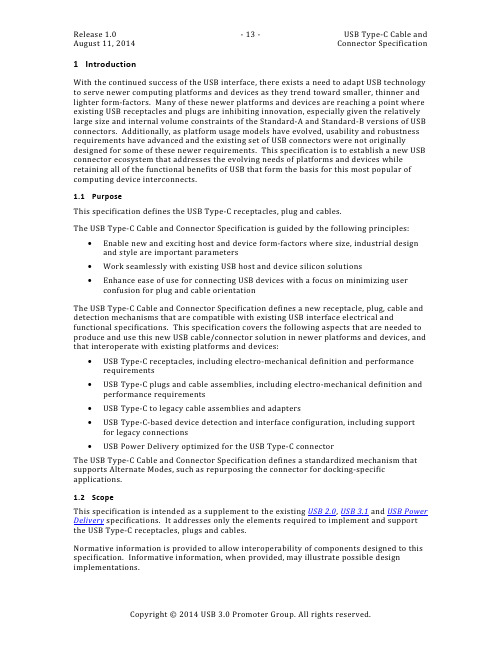
The USB Type-C Cable and Connector Specification defines a standardized mechanism that supports Alternate Modes, such as repurposing the connector for docking-specific applications. 1.2 Scope This specification is intended as a supplement to the existing USB 2.0 , USB 3.1 and USB Power Delivery specifications. It addresses only the elements required to implement and support the USB Type-C receptacles, plugs and cables. Normative information is provided to allow interoperability of components designed to this specification. Informative information, when provided, may illustrate possible design implementations.
The USB Type-C Cable and Connector Specification defines a new receptacle, plug, cable and detection mechanisms that are compatible with existing USB interface electrical and functional specifications. This specification covers the following aspects that are needed to produce and use this new USB cable/connector solution in newer platforms and devices, and that interoperate with existing platforms and devices: USB Type-C receptacles, including electro-mechanical definition and performance requirements USB Type-C plugs and cable assemblies, including electro-mechanical definition and performance requirements USB Type-C to legacy cable assemblies and adapters USB Type-C-based device detection and interface configuration, including support for legacy connections USB Power Delivery optimized for the USB Type-C connector
真正的B B业务

1h( !"! @r
4:(mOlmnJ"N;Ig&U(.mL5n4mO9’lI/df bv4:(OPS99:BOPg0-X;I-9kGw;I-Y-9’(/J )K;^rtL0F_do>?f-(Lc9XfQqIT(g!9df:9( OPS9jx.R@0x/!jjj K5UVCD0F".2{>?(7-%9 j"<g!43L
>?z21(!Tt
-.C3@ri(CDGdo>?/&QI([-k~9doB&M(K E/Gr$d79Y=>(&’zX’l5:BCDQbLfrg5@%-0l m-np.do>?G_XfiI-xl({uf-n3(LkG~WQ.@4 tT;IgLY([-WXfi;Ig-0>=JE}Mcx( +,-./00 CD.9 6lAr/do>?(TtgL_I[-}gMu(jl%do>?9*M( TtgGdo7OK9VW$Xf$di(_cgI[q-cv!L
b2M>X’l&5doa;(bfhFLXbrgCD_o*N,(a ;/J)(OP(i571w]ohS9kGxB(CD;<_;4a;(K LyG3vLAB66a;(!v"6~OP96tXBmdoa;(oAw *L6XbB!M]*+’l<5ahbvc&L){@:B!!Odoa; (:<jjja09XxB(LU/)*%J)KwTbN@+mxmb’’L;
I9Kr
1h( !"! @r
#$%&& ’()*+%$$
f-&j( !"! >?2Hdn9kG\\ "’1D<=[v"oL
SNS-032 (BMS-387032)_CDK抑制剂_345627-80-7_Apexbio

实验操作
细胞实验: 细胞系 溶解方法 反应时间 应用
慢性淋巴细胞白血病(CLL)细胞
动物实验: 动物模型 剂量 注意事项
MDA-MB-435 细胞异种移植小鼠模型
15 mg/kg;腹腔注射;每 3 天 1 次,持续约 1 个月
请于室内测试所有化合物的溶解度。虽然化合物的实际溶解度可 能与其理论值略有不同,但仍处于实验系统误差的允许范围内。
产品描述:
SNS-032(BMS-387032)是一种有效的和选择性的细胞周期蛋白依赖性激酶(CDKs)2、7 和 9 的抑制剂[1],IC50 值分别为 38 nM、62 nM 和 4 nM[2]。 CDKs 属于丝氨酸/苏氨酸激酶家族,调节细胞周期进程。有些 CDKs 与转录调控相关,在癌
细胞中经常被扰动[3]。 RNA 聚合酶 II 的 C-端结构域(CTD)Ser5 和 Ser2 磷酸化的减少表明 CDK9 和 CDK7 的抑制[1]。 在慢性淋巴细胞白血病(CLL)细胞中,SNS-032 处理 6 小时或 24 小时后导致 RNA 聚合酶 II 的 C-端结构域(CTD)Ser2 和 Ser5 磷酸化的减少,这种效应是时间和浓度依赖的,且在不 同的样品中极其一致。SNS-032 对 Ser2 磷酸化的抑制作用要强于对 Ser5 磷酸化的抑制,这 与以下事实一致,即 SNS-032 抑制 CDK9 的 IC50 值要低于抑制 CDK7 的 IC50 值,分别为 4 nM 和 62 nM。在 6 小时的处理后,CDK7 和 CDK9 的蛋白水平是稳定的,而在 24 小时的处理后, 两者均下降[4]。 在慢性淋巴细胞白血病(CLL)患者中,SNS-032 以 75 mg/m2 的总剂量注射后导致 RNA 聚合 酶 II 的 C-端结构域(CTD)Ser5 和 Ser2 磷酸化的减少,这表明 SNS-032 对 Cdk9 和 Cdk7 的 抑制,这种抑制作用在 SNS-032 开始注射后的 2 小时出现,6 小时后是明显的,而在 24 小 时后回到基线水平[1]。
Extreme Networks SLX 9640高性能固定路由器商品介绍说明书
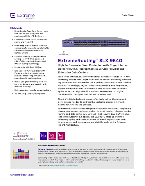
ExtremeRouting? SLX 9640
Built to Suit Your Business Needs Ext rem e Elem ent s are t he b uild ing b locks t hat allow you t o t ailor your net w ork t o your sp ecific b usiness environm ent , g oals, and ob ject ives. They enab le t he creat ion of an A ut onom ous Net w ork t hat d elivers t he p osit ive exp eriences and b usiness out com es m ost im p ort ant t o your org anizat ion.
W W W.EXTREMENETW
1
Flexib le Bo rd er Ro ut ing w it h Int ernet Scale, Ult ra-Deep Buffers,
MPLS and EVPN
The SLX 964 0 is a very p ow erful com p act d eep b uffer Int ernet b ord er rout er, p rovid ing a cost -efficient solut ion t hat is p urp ose-b uilt for t he m ost d em and ing service p rovid er and ent erp rise d at a cent ers and MA N/ WA N ap p licat ions. The rob ust syst em archit ect ure sup p ort ed by SLX-OS and a versat ile feat ure set includ ing IPv4 , IPv6, and MPLS/ VPLS w it h Carrier Et hernet 2.0 and OA M cap ab ilit ies t o p rovid e d ep loym ent flexib ilit y.
基于CYUSB3014 USB3.0总线开发技术
基于CYUSB3014 USB3.0总线开发技术[导读]本文介绍了以FPGA为控制核心,以cypress的FX3系列CYUSB3014芯片为总线接口芯片,实现了对USB3.0总线技术的开发应用,实际测试的传输速度能够达到1.43Gbps。
1.引言USB(Universal Serial Bus,通用串行总线)以其无需配置、即插即用等特性获得了广泛的应用。
2004年提出的USB2.0标准,传输速度最大能够达到480Mbps。
但在 USB3.0标准中,它的最大传输速度几乎是传统USB2.0传输速度的10倍,达到了5.0Gbps,被定义为“超高速U S B接口”。
本文基于CYPRESS的FX3系列USB3.0芯片,对USB3.0总线进行研究开发。
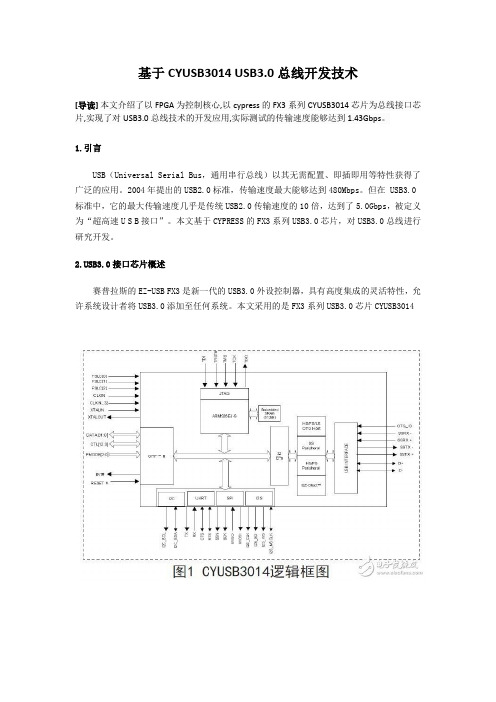
B3.0接口芯片概述赛普拉斯的EZ-USB FX3是新一代的USB3.0外设控制器,具有高度集成的灵活特性,允许系统设计者将USB3.0添加至任何系统。
本文采用的是FX3系列USB3.0芯片CYUSB3014FX3是完全兼容USB3.0 V1.0和USB2.0规范的,集成的USB2.0 OTG控制器允许芯片作为主从设备使用。
另外,它还支持一些常用的外设接口,如SPI,I2C,UART和I2S可以与外部设备进行通信。
FX3具有一个可进行完全配置的并行通用可编程接口GPIF II,它可以与任何处理器、ASIC或是FPGA连接。
它可以轻松无缝地连接至多种常用接口,比如异步SRAM、异步和同步地址数据复用式接口、并行 ATA等等。
EZ-USB FX3集成了USB3.0和USB2.0物理层(PHY)以及32位ARM926EJ-S微处理器,具有强大的数据处理能力,并可用于构建定制应用。
3.系统整体设计本系统设计主要由软件部分和硬件部分组成。
软件部分主要包括三大部分:PC机应用程序、FX3固件程序FPGA程序。
硬件部分主要由FPGA、USB3.0芯片和DDR2组成,硬件的系统框图如图2所示。