基于SEP3203的VFD控制器PT6311驱动程序设计
士兰微电子 SC16315 VFD驱动 控制电路 说明书

应用
* 微型机外设
产品规格分类
产品 SC16315
封装 QFP-44-10 X 10-0.8(S)
杭州士兰微电子股份有限公司
Http: //
版本号:1.0 2008.12.16 共14页 第1页
内部框图
SC16315
DIN
7
DOUT
6
串行数据
8 CLK
接口
9 STB
Seg1 Seg4
Seg8 Seg12 Seg16 Seg20 Seg24
00HL
00HU
01HL
01HU
02Hv
02HU DIG1
03HL
03HU
04HL
04HU
05HL
05HU DIG2
06HL
06HU
07HL
07HU
08HL
08HU DIG3
09HL
09HU
0AHL
0AHU
0BHL
0BHU DIG4
Http: //
版本号:1.0 2008.12.16 共14页 第5页
SC16315
功能描述
1、 显示 RAM 地址和显示模式
数 据 通 过 串 行 接 口 从 外 部 装 置 发 送 到 SC16315 , 并 存 储 在 显 示 RAM 和 指 定 的 地 址 中 。 SC16315的RAM地址如下图所示,以8位为单位。
OSC
5
OSC
4位锁存器
指令译码 显示存储器 定时发生器
调光电路
24位 输出锁存器
数据选择器
字符段 驱动器
Seg1/
KS1 14
Seg16/
KS16 29
Seg17/
基于dsPIC30F3011的软起动控制系统

现 煤矿 井下使 用 的智能 型 的软起 动 装置均 采用
了单 片机技 术 , 由于 单 片机 本 身 资 源 的不 足 以及 处
制核心部分 、 数字量输入输出部分 、 故障保护 电路 、 通讯 接 口电路 、 电流检 测 电路 、 三相 电压 同步 信号采
集 与晶 闸管脉 冲触发 电路 等 。其主 要 核心 是 Mi o c— r
N U Xn L ogfi / i, I n- H e
(i a oai a adT cnc o ee J un 5 60 hn ) J unV ct nl n eh i C lg , i a 4 5 ,C ia y o l a l y 4
1 引言
软起 动控制 装 置 的硬 件 部 分 包 括 D C数 字控 S
触发 控制
CPL D
管 触 发 信
号
45 8
量的存储器 、 电机控制 P WM模块 、 输入捕捉模块 、 模拟转换模块 以及 高速的现场总线接 口, 这样 , 以 dPC03 l sI3 F 0 1芯 片 为 控 制 表 1核 心 设 计 的 基 于
dPC 0 sI3 F的智 能型 防爆 软起 动 控制 装 置 , 不但 可 以 完 成 电机 的软起 动过 程 以及 正 常工作状 态下 的保 护
4 O位 的桶式 移 位器 。 dPC 0 3 1 s I3 F 0 1是 D C系列 中 的一 种 , 算速 度 S 运
有效防止了输入输 出控制 的误动作 , 并且在使用时 减 小 P B板 的 面积 , 高 了系统 的可 靠性 。 C 提 2 )驱动电路 。采用 高频 脉冲序列的方式和脉 冲变压器来产生符合要求 的具有一定规律的脉冲,
理数 据 的能 力不 强 、 长及 浮点运 算性 能差 等原 因 , 字 造 成 了其本 身应用 的 局 限性 , 数 据处 理 能 力 和 护 如 干扰 水 平有 限 , 微 机 保 护 装 置 通 常 由 多 C U 构 使 P 成, 电气元 件与 电力线 的保 护 、 控等 功能需 分别 由 测 不 同的单元 实现 , 成 其 接 线 复杂 , 用 维 护 麻 烦 , 造 使
施耐德变频器的原理解说

表 1:调速驱动与液压驱动的比较 我们可以明显的得出结论,调速驱动的优势更为突出,主要表现在:效率高,维护 方便,且成本低廉。因此,调速驱动适合在船舶行业大范围推广。
4
变频器和软启动在船舶行业上的应用方案
随着微电子技术的快速发展,电子控制技术越来越被广泛地应用于船舶行业的自动 化控制,极大地提高了整船的技术含量和自动化程度,它结构简单,所占空间小、噪音 低、对环境无污染,无极调速效率高,同时对船东来讲设备保养和维修简单,运行费用 低,因此深得国内外的船东好评。下面重点分析船舶行业四大系统采用施耐德 ATS48 软 起动器和 ATV61 变频器驱动的应用方案及主要优势。 4.1 使用电机驱动带来的好处 (1) 起动电流最大 2.5 In(ATS48)、1 In ( ATV61 ),对电网冲击小,电机的转 矩有了明显的提高,特别是低速运行的时候(可以达到 100%)。 (2) ATS48、ATV61 结构简单、重量轻、模块化结构易于安装及维护,同时故障率 低,维护成本低。 (3) 因无液压单元,故不会出现漏油现象,不会出现卡轴现象,同时无污染,且噪 声低,环保性很高,符合绝大多数港口标准要求。同时也提高了电网的利用 率,降低船舶地运行成本。
脉冲序
列
等效正弦 ACDC 2.3.1 软起动器 (1) 软起动器是一种智能化降压起动器,在起动电机时可有效地控制和限制起动电 流,可减少对电机及其驱动的设备的机械应力; (2) 在只需要软起动和软停止而不需要调速的场合可以使用软起动器; (3) 软起动器为了降低起动电流,必须实施降压起动,,同时降低了起动转矩。 2.3.2 变频器 (1) 变频器可以实现软起动和软停止; (2) 也可以根据负载的变化和系统的要求调节速度和改变输出转矩; (3) 电机起动后可以不以工频转速运行; (4) 变频器在起动电机的同时不必降低起动转矩。 2.3.3 结论 (1) 从功能上变频器可取代软起动器,但软起动器不能取代变频器; (2) 从成本上变频器高于软起动器。 2.4 关于变频器和电机使用。 对于一般的鼠笼电机来说,使用上有几个缺陷: (1) 普通的鼠笼电机低速转矩出力差,造成低速时电机带载能力差,特别是10Hz一 下时。 -2DCAC
VFD控制驱动UPD16312的原理与应用

图 ” L°¤‘–“‘’ 的接口时序
令 Œ 图 “ 所示为其命令格式 " 通过显示模式设置命令可使 L° ¤‘–“‘’ 匹配不同
结构的 ¶ ¦ ¤ 屏 " 在地址设置命令中 Œ 地址的取值范 围为 ••¨ * ‘•¨ Œ 大于 ‘•¨ 的取值被视为无效 " ’ Ž’L° ¤‘–“‘’ 的接口时序
- £ µ 对 L° ¤‘–“‘’ 的每次访问都是在 ³ ´ ¢ 信 号的下降沿开始 Œ 在 ³ ´ ¢ 的上升沿结束 Œ 访问的数 据在 £ ¬«上升沿有效 Œ 数据的低位在前 Œ 高位在 后 " 一次访问只能传送一个命令字节或一个命令字 节 ‹ 多个数据字节 Œ ³ ´ ¢ 信号下降沿后的第一个字 节为命令字节 Œ 其时序如图 ”ˆÁ‰ ! ˆÂ‰ 所示 " 图 ”ˆÃ‰ 是以地址自加 ‘ 方式更新显示 ² ¡ - 的时序 Œ £ ÏÍ ÍÁÎÄ‘ * £ ÏÍ ÍÁÎÄ ” 分别是显示模式设置命 令 ! 数据设置命令 ! 地址设置命令和显示控制命令 Œ ¤ÁÔÁ‘ * ¤ÁÔÁ Î 为显示数据 Œ 显示数据最多为 ’’ 个 " L° ¤‘–“‘’ 在键值信号同步产生器的作用下可 在每个显示周期的最后来扫描键盘 Œ 然后将 ” 位键 值数据依次放在键值 ² ¡ - 中 "
• •˜ •
5国外电子元器件6’••“ 年第 ‘ 期 ’••“ 年 ‘ 月
p 新特器件应用
¶ ¦¤控制•驱动器 L°¤‘–“‘’ 的原理与应用
第二炮兵工程学院
梁建辉
第二炮兵第一研究所 杨金岩
Principle and Application of V FD Controller/ Driver LPD16312
是很细的钨丝 Œ 在其外部包裹一
PT6311在DVD前面板控制电路中的应用

① 具有多种显示模式 ,其显示模式可在 8 2 段到 l 字×2 字x0 6 1 段的范围内选择; ② 具有按键扫描 的功能,按键矩阵为 1x ; 24 ③ 显示亮度可调,共有 8 个亮度等级; ④ 具有高电压输出; ⑤ 具有一个 4 位通用输入 口和一个 5 通道 的 L D输出口; E
Ab t a t h sa t l t d c d t ep ro ma c h r ce it , o t l o s r c :T i ri e i r u e e r n e c a a trsi c n r mma d, e l e wa f r g a mig is r c in c n o h f c oc n r a i y o o rm z p n tu t n o n sp a t l p i t f 6 1 nt lc r c r i o a d i r c ia p l a i no T 3 i e ee ti i u t f t c a c o P 1 h c c DVD e o d rSf n a e . d c re ’ r t n 1 o p
关键 词 :P 6 I;V D;DV T3I F D;前 面板
中图分类号 :T 7 0 N 1
文献标识码 :A
文章编号 :17 —2 82 0 )10 5 -3 6 25 9 (0 70 —0 60
App ia i n o l to f c PT6 s d i h 3 1u e n t e 1
c n r li c r ui l’’ ’ ’ r n a l o t o ln ̄c c tO VD f o tpa i Ui D ’、 、 7 S ne
Ⅵ f J n. ua u h
(h s s n l t nc nomain n ier g pr n.H nnIstt o c ne dTc n lg, uy g4 4 0 , hn) P yi d e r iIfr t gnei at t u a tue f i c e hoo yY ea 10 6C ia ca E co oE n De me , ni S e a n n
VFD驱动原理

深圳行銷處 王永虎 4月22日
PDF created with FinePrint pdfFactory Pro trial version
不仅仅是VFD driver 的PT6312/6311。
• 阳极区段记忆体 • 变化丰富的VFD往往吸引较多的客户,但愈多 的变化MCU就需要愈多的MEMORY来储存阳 极区段的资料。PT6312/6311本身内部就提供 了为数不少的记忆体以供使用,所以MCU可直 接利用这些记忆体里储存阳极区段资料的变化。 设计者便不需额外找记忆体了。
PT6312/6311的架构图及应用线路图
LED Output port General purpose input port
MCU
DIN Hale Waihona Puke OUT CLK STBGrid
PT6311
segment
VFD
Key source
key
keyboard
深圳行銷處 王永虎 4月22日
Page 18 of 23
Page 15 of 23
深圳行銷處 王永虎 4月22日
PDF created with FinePrint pdfFactory Pro trial version
PT6312/6311的架构图及应用线路图
PT6311
Page 16 of 23
深圳行銷處 王永虎 4月22日
• 十、总结。
Page 2 of 23
深圳行銷處 王永虎 4月22日
PDF created with FinePrint pdfFactory Pro trial version
何谓VFD
• VFD(Vacuum Fluorescent DisPlay)萤光显示幕是由真 空管发展出来的显示元件,是利用加热灯丝产生电子, 再经由栅极(Grid)正电压的加速,使电子撞击涂有 萤光体的阳极区段(Anode, Segment)而发光,有效的 控制VFD栅极用阳极区段电压,便可使整个VFD 萤光 显示幕做正确的显示。 • VFD 的发光方式是由电子撞击萤光体所产生的,所以 VFD的属于自体发光元件。由于VFD 可自体发光,所 以并不需要辅助发光的背光装置LCD(Liquid crystal display)液晶显示器则需用要背光,且藉著阳极区段 的萤光涂料不同而形成多彩醒目的效果。
6313微电脑pH ORP Temp控制器使用说明书
操作手册MODEL 6313微电脑pH / ORP/Temp.控制器JENCO ELECTRONICS, LTD.上海任氏电子有限公司目录页码I. 产品检视与安装2 II. 简介3 III. MODEL 6313 的使用 4A.前面板与按键说明 4B. 显示器说明 5C. 端子接线图 6D. 开机/关机7 IV. MODEL 6313的显示模式8A. 主(正常)显示模式8B. 校正/ 设定模式9a. 密码检查画面9b. 校正/设定模式选择画面101. “pH”控制模式的设定10i. 温度探棒的选择画面/ii.“校正液一”的选择画面/ iii.“校正液二”的选择画面/ iv.抵补电位的校正画面/ v.斜率的校正画面/vi.电极效率显示画面/pH 校正的步骤/vii.4mA设定画面/viii 20mA设定画面ix. “继电器1~ 继电器2”的设定/x. 密码的设定2. “ABS mV”控制模式的设定15i. 温度探棒的选择画面/ii. 4mA设定画面/iii 20mA设定画面/iv.“继电器1~继电器2”的设定/ v.密码的设定3. “REL mV”控制模式的设定17i. 温度探棒的选择画面/ii.抵补电位的设定画面/iii.4mA设定画面iv. 20mA设定画面/v. “继电器1~ 继电器2”的设定/vi.密码的设定V. 关于继电器(CONTROLLING THE RELAYS) 20A. 隔离电压20B. 继电器输出负载20C. 关于继电器的动作、设定点、迟滞20 VI. 关于 4 - 20 mA 隔离输出21A. 隔离电压21B. 隔离电流的负载22C. 线性控制输出22 VII. 错误显示与排除方法23 VIII. pH 校正液与温度的关系24 IX. 规格25 X. 按键的图标流程图26A. pH模式按键的图标流程图26B. ABSOLUTE mV模式按键的图标流程图27C. RELATIVE mV模式按键的图标流程图28 XI. 保证29I. 产品检视与安装产品检视小心地打开包装, 检视仪器及配件是否有因运送而损坏, 如有发现损坏, 请立刻通知任氏的代理商, 并原包装寄回送检, 直到使用者满意为止。
SmartVFD COMPACT 31-00075-01 变频电机驱动说明文件说明书
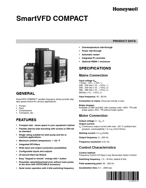
PRODUCT DATA31-00075-01SmartVFD COMPACTGENERALSmartVFD COMP ACT variable frequency drives provide step less speed control for various applications:•Pumps •Fans•Compressors •Conveyors, etc.FEATURES•Compact size - saves space in your equipment cabinet •Flexible side-by-side mounting with screws or DIN-rail as standard •Single rating suitable for both pump and fan or machine applications •Maximum ambient temperature: + 122 °F •Integrated RFI-filters•Wide input and output connection possibilities •Configurable inputs and outputs •30 second Start-Up Wizard•Easy “keypad to remote” change with 1 button •Parameter upload/download even without main power to the drive with HVFDCABLE accessory •Quiet motor operation with 4 kHz switching frequency•Overtemperature ride-through •Power ride-through •Automatic restart •Integrated PI controller •Optional NEMA 1 enclosureSPECIFICATIONSMains ConnectionInput voltage U in:115Vac, -15%...+10% 1~208…240 Vac (-15…+10%), 1~208…240 Vac (-15…+10%), 3~380…480 Vac (-15…+10%), 3~600Vac (-15…+10%), 3~Input frequency: 45…66 HzConnection to mains : Once per minute or lessBrake chopper:Available on MI2 and MI3, with 3-phase units: 100% *TN with brake option; 30% *TN without brake option.Motor ConnectionOutput voltage: 0 - U in , 3~Output current:I N : Continuous output current with max. +50 °C ambient tem-perature, overloadability 1.5 x I N (1min/10min)Starting current: 2 x I N 2s/20s Output frequency: 0…320 Hz Frequency resolution: 0.01 HzControl CharacteristicsControl method:Frequency Control U/f Open Loop Sensorless Vector Control Switching frequency: 1.5...16 kHz; default 6 kHz Field weakening point: 30…320 Hz Acceleration time:0.1…3000 secSMARTVFD COMP ACT31-00075—012Deceleration time: 0.1…3000 secBraking torque:100% *TN with brake option (only in 3~ drives sizes MI2 and MI3)30%*TN without brake optionAmbient ConditionsOperating temperature:+ 14 °F (-10 °C) (no frost)…+ 104/122 °F(40/50 °C) for 115 Vac, 460 Vac and 600 Vac and + 104 °F (40 °C), for 208 Vac/230 Vac, rated loadability I N Storage temperature: -40 °F (-40 °C)…+158 °F (+70 °C)Air quality :Chemical vapors:IEC 721-3-3, unit in operation, class 3C2Mechanical particles:IEC 721-3-3, unit in operation, class 3S2Altitude:100% load capacity (no derating) up to 1000 m1% derating for each 100 m above 1000 m; max. 2000 m Relative humidity:0…95% RH, non-condensing, non-corrosive, no dripping water Vibration: 3...150 HzEN50178, EN60068-2-6:Displacement amplitude 1(peak) mm at 3...15.8 Hz Max acceleration amplitude 1 g at 15.8...150 Hz ShockEN50178, IEC 68-2-27:UPS Drop T est (for applicable UPS weights)Storage and shipping: max 15 g, 11 ms (in package)Enclosure class: Open chassis, NEMA 1 kit optionalElectro Magnetic Compatibility (EMC)Immunity:Complies with EN50082-1, -2, EN61800-3, Category C2Emissions:115V: Complies with EMC category C4230V: Complies with EMC category C2; with an internal RFI filter400V: Complies with EMC category C2; with an internal RFI filter600V: Complies with EMC category C4All: No EMC emission protection (Honeywell level N): Without RFI filterSafety:For safety: CB, CE, UL, cULFor EMC: CE, CB, c-tick(see unit nameplate for more detailed approvals)Control connectionsAnalog input voltage:0...+10V , Ri = 200k Ω (min), Resolution 10 bit, accuracy ±1%, electrically isolated Analog input current:0(4)…20 mA, Ri = 200Ω differential resolution 0.1%, accuracy ±1%, electrically isolated Digital inputs: 6 positive logic; 0…+30 VDC Voltage output for digital inputs:+24V , ±20%, max. load 50 mA Output reference voltage :+10V , +3%, max. load 10 mAAnalog output :0(4)…20 mA; RL max. 500Ω; resolution 16 bit; accuracy ±1%Digital outputs :Relays:2 programmable relay outputs (1 NO/NC and 1 NO), Max.switching load: 250 Vac/2 A or 250 Vdc/0.4 A Open collector:1 open collector output with max. load 48 V/50 mAProtectionsOvervoltage protection:875VDC in HVFDCDXCXXXXXXX 437VDC in HVFDCDXBXXXXXXX Undervoltage protection:333VDC in HVFDCDXCXXXXXXX 160VDC in HVFDCDXBXXXXXXXEarth-fault protection:In case of earth fault in motor or motor cable, only the fre-quency converter is protected Unit overtemperature protection: YES Motor overload protection: YESMotor stall protection (fan/pump blocked): YES Motor underload protection(pump dry / belt broken detection): YES Short-circuit protection of +24V and +10V reference voltages: YESOvercurrent protection: T rip limit 4,0*I N instantaneouslySMARTVFD COMP ACT331-00075—01MODELSTable 1.Nominal Voltage Nom. HP (Nom. Current)EMC Filter Full IO (6DI, 2AI, 1AO,1DO, 3RO, Modbus)Frame Size: MI1Dimensions: 6.2" H x 2.6" W x 3.9" D460V3~in 3~out0.5 HP (1.3 A)No HVFDCD3C0005F00EMC HVFDCD3C0005F010.75 HP (1.9 A)No HVFDCD3C0007F00EMC HVFDCD3C0007F011 HP (2.4 A)No HVFDCD3C0010F00EMC HVFDCD3C0010F01208/230V 1~in 3~out 0.25 HP (1.7 A)EMC HVFDCD1B0003F010.5 HP (2.4 A)EMC HVFDCD1B0005F010.75 HP (2.8 A)EMC HVFDCD1B0007F01208/230V 3~in 3~out 0.25 HP (1.7 A)No HVFDCD3B0003F000.5 HP (2.4 A)No HVFDCD3B0005F00Frame Size: MI2 Dimensions: 7.7" H x 3.5" W x 4.0" D460V3~in 3~out1.5 HP (3.3 A)No HVFDCD3C0015F00EMC HVFDCD3C0015F012 HP (4.3 A)No HVFDCD3C0020F00EMC HVFDCD3C0020F013 HP (5.6 A)No HVFDCD3C0030F00EMC HVFDCD3C0030F01208/230V 1~in 3~out 1 HP (3.7A)EMC HVFDCD1B0010F011.5 HP (4.8 A)EMC HVFDCD1B0015F012 HP (7 A)EMC HVFDCD1B0020F01208/230V 3~in 3~out 1 HP (3.7A)No HVFDCD3B0010F002 HP (7 A)No HVFDCD3B0020F00115V/230V 1~in 3~out0.25 HP (1.7 A)No HVFDCD1A0003F000.5 HP (2.4 A)No HVFDCD1A0005F001 HP (3.7A)NoHVFDCD1A0010F00SMARTVFD COMP ACT31-00075—014PRODUCT IDENTIFICATION CODEFig. 1. Product Identification Code.Frame Size: MI3Dimensions: 10.2" H x 3.9" W x 4.3" D460V3~in 3~out4 HP (7.6 A)No HVFDCD3C0040F00EMC HVFDCD3C0040F015 HP (9 A)No HVFDCD3C0050F00EMC HVFDCD3C0050F017.5 HP (12 A)No HVFDCD3C0075F00EMC HVFDCD3C0075F01208/230V 1~in 3~out 3 HP (1 A)EMC HVFDCD1B0030F01208/230V 3~in 3~out 3 HP (11 A)No HVFDCD3B0030F00115V/230V 1~in 3~out 1.5 HP (4.8 A)No HVFDCD1A0015F00600V3~in 3~out1 HP (2 A)No HVFDCD3D0010F002 HP (3.6 A)No HVFDCD3D0020F003 HP (5 A)No HVFDCD3D0030F005 HP (7.6 A)No HVFDCD3D0050F007.5 HP (10.4 A)NoHVFDCD3D0075F00Nominal Voltage Nom. HP (Nom. Current)EMC Filter Full IO (6DI, 2AI, 1AO,1DO, 3RO, Modbus)SMARTVFD COMP ACT531-00075—01MECHANICAL DIMENSIONS AND MOUNTINGThere are two possible ways to mount the SmartDrive Compact onto the wall; either screw or DIN-rail mounting. The mounting dimensions are also given on the back of the inverter.Fig. 2. Mounting with screws or DIN-rail.Fig. 3. Dimensions in inches.Mechanical size H1H2H3W1W2W3D1D2MI1 6.2 5.8 5.4 2.6 1.50.2 3.90.3MI27.77.2 6.7 3.5 2.50.2 4.00.3MI310.39.99.53.93.00.24.30.3SMARTVFD COMP ACT31-00075—016COOLINGForced air flow cooling is used in all SmartDrive Compact drives. Enough free space shall be left above and below the inverter to ensure sufficient air circulation and cooling. SmartDrive Compact products can be mounted side by side. Y ou will find the required dimensions for free space and cooling air in the tables below:Table 2.Table 3.CABLING AND FUSESUse cables with heat resistance of at least +158 °F (+70 °C). The cables and the fuses must be dimensioned according to the following tables. The fuses function also as cable overload protection. These instructions apply only to cases with one motor and one cable connection from the inverter to the motor. In any other case, contact your Honeywell Sales Representative.Table 4.Table 5. Cable and fuse sizes for 208-240 V .Table 6. Cable and fuse sizes for 380-480 V .Mechanical size Free space above [inches]Free space below [inches]MI1 4.0 2.0MI2 4.0 2.0MI34.0 2.0Mechanical size Cooling air required [CFM]MI1 5.89MI2 5.89MI317.7Connection Cable typeMains cable Power cable intended for fixed installation and the specific mains voltage. Shielded cable not required. (NKCABLES/MCMK or similar recommended)Motor cablePower cable equipped with compact low-impedance shield and intended for the specific mains voltage. (NKCABLES /MCCMK, SAB/ÖZCUY -J or similar recommended). 360º grounding of both motor and FC connection required to meet the standards.Control cableScreened cable equipped with compact low-impedance shield (NKCABLES /Jamak, SAB/ÖZCuY -O or similar).Size Type (power)I N [A]Fuse [A]Mains cable Cu[AWG]Terminals cable size (min/max)Main terminal [AWG]Earth terminal [AWG]Control terminal [AWG]Relayterminal [AWG]MI1P25 - P751,7 – 3,710 2 x 15 + 1515 - 1115 - 1120 - 1520 - 15MI21P1 - 1P54,8 – 7,020 2 x 13 + 1315 - 1115 - 1120 - 1520 - 15MI32P211322 x 9 + 915 - 915 - 920 - 1520 - 15Size Type (power)I N [A]Fuse [A]Mains cable Cu[AWG]Terminals cable size (min/max)Main terminal [AWG]Earth terminal [AWG]Control terminal [AWG]Relayterminal [AWG]MI1P37 - 1P11,9 – 3,36 3 x 15 + 1515 - 1115 - 1120 - 1520 - 15MI21P5 - 2P24,3 – 5,610 3 x 15 + 1515 - 1115 - 1120 - 1520 - 15MI33P0 - 5P57,6 - 1220 3 x 13 + 1315 - 915 - 920 - 1520 - 15SMARTVFD COMP ACTFig. 4. SmartDrive Compact power connections.Fig. 5. SmartDrive Compact control connections wiring.Fig. 6. SmartVFD Compact control connection terminals.731-00075—01SMARTVFD COMP ACT31-00075—018The table below shows the SmartDrive Compact control connections with the terminal numbers.Fig. 7. Control inputs and outputs – API Full.FEATURES / FUNCTIONSEasy to set-up featuresTable 7.FeatureFunctionsBenefit30 second Start-up wizardSimple 4 step wizard for specific applications Activate wizard by pressing stop for 5 seconds Tune the motor nominal speed Tune the motor nominal currentSelect mode (0=basic, 1= Fan, 2 = Pump and 3 = Conveyor)Fully configured inverter for the application in question Ready to accept 0-10V analog speed signal in just 30 seconds“Keypad – Remote” OperationPush the navigation wheel for 5 seconds to move from remote control (I/O or Fieldbus) to manual mode and back.Single button operation to change the control tomanual (keypad) and back. Useful function whencommissioning and testing applicationsQuick Setup MenuOnly the most commonly used parameters are visible in basic view to provide easier navigation. The full view can be seen after P13.1 Parameter conceal is deactivated by changing the value to 0.Easy navigation through the most common parameters SmartVFD Commissioning Tool1.Parameter sets can be uploaded and downloaded with thistool.2.Easy to use PC-tool for commissioning the SmartVFD Invert-ers. Connection with HVFDCABLE and MCA adapter, (HVFD-CDMCAKIT/U), to the USB port of the PC. PC-tools available for download free of charge fromhttps:///en-US/support/commercial/software/vfds/Pages/default.aspxParameter copying easily from 1 inverter to another.Easy download of parameter sets created with PC-tool Parametering with PC Saving settings to PC Comparing parameter settingsSMARTVFD COMP ACT931-00075—01Compact and robust design with easy installationTable 8.Uninterruptible operation functionsTable 9.VFD and motor control featuresTable 10.OPTIONAL ACCESSORIESTable 11. SmartVFD COMPACT Accessories.FeatureFunctionsBenefitCompact size Minimum free space above and below the drive is required for cooling airflow.Minimum space requirementsIntegrated RFI-filtersThe units comply with EN61800-3 category C2 as standard. This level is the required level for public electricity networks such as buildings.Easy selection and installation of products.Space savingsCost savings Single power ratingSingle power suitable for both pump and fan or machine applicationsEasy selectionMax. ambient temperature + 122 °FHigh maximum ambient operating temperature Uninterruptible operationSide by side mounting with screws or DIN-rail asstandardSmartDrive Compact can be mounted side by side with no space between the units either with screws or on DIN-rail as standard.Dimensions for screw mounting can be found also on the back of the inverter.Easy installationSpace savings FeatureFunctionsBenefitOvertemperature ride-through Automatically adjusts switching frequency to adapt to unusual increase in ambientUninterruptible operationPower ride-through Automatically lowers motor speed to adapt to sudden voltage drop such as power lossUninterruptible operation Auto restart functionAuto restart function can be configured to make VFD restart automatically once fault is addressedUninterruptible operationFeatureFunctionsBenefitFlying startAbility to get an already spinning fan under speed control Improved performance Ease of application Inbuilt PI- controllerCapability to make a standalone system with sensor connected directly to the inverter for complete PI- control.Cost savingModel NumberDescriptionHVFDCABLE/U SmartVFD Commissioning Cable and USB Adaptor HVFDCDMCA/U Compact Commissioning Device HVFDCDMCAKIT/U Compact Commissioning Kit HVFDCDNEMA1FR1/U Compact NEMA 1 Kit Frame Size1HVFDCDNEMA1FR2/U Compact NEMA 1 Kit Frame Size2HVFDCDNEMA1FR3/U Compact NEMA 1 Kit Frame Size3HVFDCDTRAINER/UCompact Training Demonstration KitSMARTVFD COMP ACT31-00075—0110SMARTVFD COMP ACT 1131-00075—01SMARTVFD COMP ACTAutomation and Control Solutions Honeywell International Inc.1985 Douglas Drive North Golden Valley, MN 55422 ® U.S. Registered T rademark© 2015 Honeywell International Inc. 31-00075—01 M.S. 01-15 Printed in United StatesBy using this Honeywell literature, you agree that Honeywell will have no liability for any damages arising out of your use or modification to, the literature. You will defend and indemnify Honeywell, its affiliates and subsidiaries, from and against any liability, cost, or damages, including attorneys’ fees, arising out of, or resulting from, any modification to the literature by you.。
- 1、下载文档前请自行甄别文档内容的完整性,平台不提供额外的编辑、内容补充、找答案等附加服务。
- 2、"仅部分预览"的文档,不可在线预览部分如存在完整性等问题,可反馈申请退款(可完整预览的文档不适用该条件!)。
- 3、如文档侵犯您的权益,请联系客服反馈,我们会尽快为您处理(人工客服工作时间:9:00-18:30)。
自动化设备 工业仪器仪表及汽车等各种领域中
由于它结构简单 体积小 重量轻 越来越多的
为系统开发商选用 本文以 VFD 控制器 PT6311 为例 介绍了其内部结构 工作原理 并且详细阐述
了在东南大学 ASIC国家工程中心自主开发的 ASIXOS嵌入式操作系统下面开发驱动程序的过程和 方法 1 同时给出在嵌入式 ASIXOS操作系统中 基于SEP3ZO3微处理器和 CycloneEP1C3T144平 台的 PT6311驱动程序设计 SEP3ZO3是一款基于 ARM7TDMI的SOC芯片 由东南大学 ASIC 国家 工程中心自主开发 Z
下面是接口程序的参考:
voidRefreshVFD(char# stringD 4
Init_VFD(D;/# 设置显示状态 清空显示 RAM 熄灭 VFD显示 #/ for(i=O;i" 字符串长度-1;i++D input_digit(D;/# 输入数据到 VFD 的显示 RAM #/ dispctrl(dimmer_level disp_onD;/#选择亮度 点 亮 VFD屏 #/ }
ent_int(D;/# ASIXOS进入中断标准操作 保存数据到 堆栈 #/ mask_ir}(intnumD;/# 屏蔽中断号对应的中断 #/ xxx_isr(D;/# 进入中断处理程序 #/ unmask_ir}(intnumD;/# 打开中断 #/ ret_int(D;/# ASIXOS进入中断标准操作 从堆栈弹 出数据 #/ }
在本模块方案中 硬件方案主要是将一个简单 的 SPI 烧 入 FPGA 中 通 过 数 据 和 地 址 总 线 与
图3!PT6311与 CycloneEP1CT144和 SEP3ZO3接口示意图
SEP3ZO3 相 连 FPGA 的 中 断 线 通 过 GPIO 的 PORTE引脚9引出到 SEP3ZO3芯片的中断控制 器 FPGA 中的 SPI通过 GPIO 口的 PORT C 与 PT6311的数据 时钟 片选相连 SPI和 FPGA 中 的其他模块各自的中断线通过一个或门连到 FPGA 的中断线上
中断服务例程:
PT6311_isr(D 4
UNSelectPT6311; ClearPortEint;/# 清 除 FPGA 接 到 SEP3ZO3 的 PORTE 口中断 #/ maskFPGAint;/# 屏掉 FPGA 中的SPI内部中断 #/ set_flg(D;/# 设置SPI传输完成标志 #/ }
ASIXOS作为东南大学 ASIC工程中心独立开 发的嵌入式操作系统 其设备驱动程序都在内核
即操作系统空间实现 将有关的设备的驱动程序
和数据结 构 静 态 的 连 接 在 内 核 映 像 中 1 ASIXOS设备的驱 动 程 序 为 应 用 程 序 屏 蔽 硬 件 设 备 细 节 因此 设备驱动程序是应用程序和具体硬件
l!VFD 模块系统介绍
l.l!VFD 屏介绍 VFD 根据结构 一 般 可 分 为 二 极 管 和 三 极 管 两
种 根据显示内容可分为 数字显示 字符显示 图案
显示 点阵显示 根据驱动方式可分为 静态驱动 直
流 和动态驱动 脉冲 显示发光形式有点阵式1 数字显示 动态驱动 l.2!VFD 屏驱动器 PT63ll介绍
间 Tr"ZOOms 可以运用于税控收款机 银税一体机和音响等方面
关键词!嵌入式 ASIXOS操作系统 PT6311SEP3ZO3处理器 模块刷新时间Tr
中图分类号!TP368!!
文献标识码!A!!文章编号!l005-9490200602-0565-04
!!由于 VFD VacuumFluorescentDisplay 可以 做多色彩显示 亮度高 又可以用低电压来驱动 易
在 PT6311 驱 动 程 序 中 打 开 中 断 是 由 PT6311的接口程序来完成0所以在 PT6311的中
断处理中 没 有 unmask_ir}这 个 操 作0PT6311_ isr的设计相对比较简单 只 需 要 对 SPI的 传 输 完 成做处理0
中断处理程序主要负责传输完成之后清除中
断 拉高片选 之后通过系统调用set_flg(D设置传 输完成标志 通知系统传输已经完成0
Abstract ThispapertakesVFDcontrollerPT6311asanexampleandintroducesitsinternalstructureand howitworks.TheprocessandmethodofdevicedriveriselaboratedinembeddedASIXOSoperation.The devicedriverbasedoninterruptofVFDcontrollerPT6311onSEP3ZO3isgiven.Theconclusionisthatthe timeofrefreshingisunderZOOmsandthemodulecouldusedinFiscalcashregister BankandFiscalintegratedregisterand~I-FIComponents KeywordsembeddedASIXOS PT6311SEP3ZO3microprocessor modulerefreshingtimeTr EEACC l265F
的接口 它是操作系统内核的一个部分 其主要的
功能如下 4 "对设备初始化和释放 #读写应用 程序传送给硬件的数据和回写硬件请求的数据 $ 检测和处理设备的异常并进行处理 %对硬件设备 的相关控制
2.l!VFD 设备初始化程序 初始化函数InitVFD 主要完成以下工作 "设置显示模式 #设置数据为固定地址 $清
数据由SEP3ZO3通过总线发送到 FPGA 中的 SPI里 SPI通过 GPIO 口向 PT6311提供时间和 符合 PT6311 时 序 要 求 的 数 据 当 数 据 传 输 完 毕 时 由SPI发生传输完成中断通知SEP3ZO3 最后 PT6311完成对 VFD屏的控制
2!PT63ll驱动程序的设计
2.2!PT63ll的接口程序 PT6311接 口 程 序 提 供 给 应 用 程 序 函 数 Re-
freshVFD(#stringD 应 用 程 序 只 需 要 调 用 RefreshVFD即可刷新 VFD 屏幕上的内容0RefreshVFD 通 过 3 个 步 骤 完 成 刷 新 任 务:" 初 始 化 PT6311 #向显示 RAM 区写入数据 $点亮 VFD
下面是初始化 VFD程序的参考
第Z期
夏!潇!凌!明等"基于SEP3ZO3的 VFD控制器 PT6311驱动程序设计
567
voidInitVFD(voidD 4
SelectDispMode(VFD_13_15D;/# 设置显示模式 #/ DataSetting(ISFIXADDRD;/# 设置地址查询方 式为固定地址 #/ clear_vfd(D;/#清空 VFD的显示 RAM 区 #/ DispControl(PULSEWID_4_16 OD;/#设置 VFD 电平脉冲时间 #/ }
凌!明 197Z- 男 讲师 主要研究领域为嵌入式实时操作系统及相关开发平台 俞!超 1979- 女 硕士研究生 主要研究方向为嵌入式系统设计与应用
566
!!!!电!子!器!件!!!!
第Z9卷
图1!PT6311内部结构图
VFD屏中每个段 SEG 对应着 PT6311 中显 示存储区的一个bit 通过对这个 bit置1就可以点 亮对应的段 而每个数字最多对应着ZO个段 根据 选择的工作方式的不同 有着不同的对应关系
2.3!PT63ll设备的底层中断处理程序 PT6311底 层 驱 动 程 序 是 和 SPI挂 钩 当 SPI
完成传输之后 在SPI的中断状态寄存器置传输完 成位0跳到 VFD的中断处理程序 ENT_INT_VFD (D中0在 ASIXOS操作系统中 进入中断有个标准 的处理过程 1I:
voidENT_INT_xxx(voidD 4
台湾PrincetonTechnologyCorp的PT6311芯 片最高输出电压为 35V 具有 1Zsegments S 16 digits到 ZOsegmentsS 8digits多种显示模式的 选择 8级调光器 串行接口的 MCU3
收稿日期!ZOO5-O7-O1 作者简介!夏!潇 1981- 男 硕士研究生 主要研究方向为嵌入式系统设计与应用 sttr!
第29卷!第2期 2006年6月
电子器件
ChineseJournalofelectron Devices
Vol.Z9!No.Z Jun.ZOO6
DesignofVFDControllerPT63llDriveronSEP3203
XIAXiaO LING\ing YUChaO
NantiOna ASICS$stemengineeringCenter SOutheastUnioerist$ NanjingZ1OO96 China
控制的数据 DI和片选以及时钟通过一个串口 输入到PT6311 如果是控制命令 则经过命令解码 器发 到 调 光 电 路 如 果 是 数 据 则 存 放 到 显 示 RAM 区中 经 过 ZObit的 输 出 锁 存 分 为 两 个 部 分 一部分1Zbit发送到段驱动电路 对应着1 1Z 段 另外8bit送到数据选择器 然后送到多元驱动 器 多元驱动器可以驱动第13段 ZO段 也可以 驱动 Grid9 Grid16 在不同的模式选择下面会有 不同的驱动 比如 选择的显示模式是16段 1Z个 digit 此时 MultiplexedDriver的前4bit驱动13 -16段 后4bit驱动 Grid9! Grid16 低8bit的 Grid由 Grid驱动电路直接驱动 当 Grid对应的 RAM 区中有数据时 相应的 Grid中的段被点亮