感应加热器教程 3kw
感应加热电源操作规程
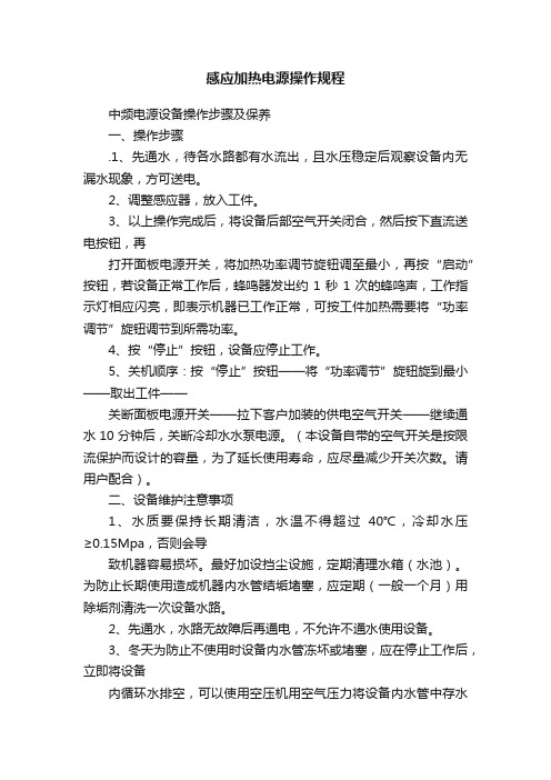
感应加热电源操作规程中频电源设备操作步骤及保养一、操作步骤.1、先通水,待各水路都有水流出,且水压稳定后观察设备内无漏水现象,方可送电。
2、调整感应器,放入工件。
3、以上操作完成后,将设备后部空气开关闭合,然后按下直流送电按钮,再打开面板电源开关,将加热功率调节旋钮调至最小,再按“启动”按钮,若设备正常工作后,蜂鸣器发出约1秒1次的蜂鸣声,工作指示灯相应闪亮,即表示机器已工作正常,可按工件加热需要将“功率调节”旋钮调节到所需功率。
4、按“停止”按钮,设备应停止工作。
5、关机顺序:按“停止”按钮——将“功率调节”旋钮旋到最小——取出工件——关断面板电源开关——拉下客户加装的供电空气开关——继续通水10分钟后,关断冷却水水泵电源。
(本设备自带的空气开关是按限流保护而设计的容量,为了延长使用寿命,应尽量减少开关次数。
请用户配合)。
二、设备维护注意事项1、水质要保持长期清洁,水温不得超过40℃,冷却水压≥0.15Mpa,否则会导致机器容易损坏。
最好加设挡尘设施,定期清理水箱(水池)。
为防止长期使用造成机器内水管结垢堵塞,应定期(一般一个月)用除垢剂清洗一次设备水路。
2、先通水,水路无故障后再通电,不允许不通水使用设备。
3、冬天为防止不使用时设备内水管冻坏或堵塞,应在停止工作后,立即将设备内循环水排空,可以使用空压机用空气压力将设备内水管中存水排出。
4、为防止触电,应经常检查接地线是否可靠,更换感应器时应停水、停电后方可拆换。
5、设备工作现场环境一般比较恶劣,工作中防止粉尘、水汽、油烟等进入设备内部,一般工作一周应打开设备侧门将设备内粉尘等杂物用空气压缩机清理干净,清理后应在不工作的前提下打开设备风机吹干一段时间,一般十几分钟即可。
若工作环境特别恶劣,建议每天工作前进行清理,并且先预开风机十分钟后,再开始操作。
操作时注意不要接触到设备内的连线。
6、设备出现故障应由专业人员检修,如有疑问,请及时与我公司客服中心或就近办事处联系。
工频感应加热器操作规程

工频感应加热器操作规程1. 引言工频感应加热器是一种广泛应用于工业生产中的加热设备。
为了保证加热设备的安全运行和有效利用,制定和遵守操作规程是必要的。
本文档旨在规范工频感应加热器的操作流程,确保操作人员的安全以及设备正常运行。
2. 设备参数参数值加热功率500kW加热频率50Hz加热器输入电压380V加热器控制电压220V3. 操作步骤3.1. 准备工作在启动加热器之前,必须进行以下准备工作:1.检查环境温度和湿度是否适宜,确保设备周围没有易燃或易爆物品;2.检查加热器的电源是否正常接地,确保安全接地;3.检查加热器的冷却系统是否正常工作,确保设备在加热过程中能够及时冷却;4.检查加热器的传感器和控制系统是否正常工作,确保能够准确控制加热器的加热功率;5.穿戴个人防护装备,包括耐高温手套、护目镜等。
3.2. 启动加热器按照以下步骤启动加热器:1.打开加热器的电源开关;2.将加热器的控制电压设定为所需的数值;3.设置加热器的加热功率;4.检查加热器的运行状态指示灯,确保加热器正常运行。
3.3. 加热操作在加热操作过程中,应注意以下事项:1.加热器的载物体积不得超过规定范围;2.加热器的工作电流不得超过额定电流;3.加热过程中应监控加热器的温度和功率;4.如需调整加热功率,必须先停止加热操作,进行调整,并在调整完成后重新启动加热器;5.在加热过程中,不得随意触摸加热器以及加热物体,以免烫伤。
3.4. 关闭加热器在加热操作完成后,按照以下步骤关闭加热器:1.将加热功率设定为零;2.关闭加热器的电源开关;3.确保加热器的运行状态指示灯熄灭;4.检查加热器的冷却系统,确保设备能够及时冷却。
4. 应急措施在使用工频感应加热器时,有可能出现以下紧急情况:1.加热器过载:此时应立即切断电源,并检查故障原因,必要时进行维修;2.加热器温度过高:此时应停止加热操作,并检查冷却系统,确保设备及时冷却;3.加热物体意外脱落:此时应立即停止加热操作,并采取适当措施将脱落物处理干净。
电磁感应加热器使用方法
的事情也是颠来倒去的相同。即使一样,每次想起来都
热方式性能
上的差别,电磁加热圈已降低约 30%功率使 用,并且在电磁加热控制器上设计了功率调整及 功率保护
功能。所以调试过程相当简单,用户可按说 明自行调试。
电磁加热圈在塑料制品、塑料薄膜、管材、 型材及类似行业等厂家进行了应用,取得了较好 的效果
操作程序无任何影响和改变。已广泛应用于 塑料加工及其类似加热行业。
的事情也是颠来倒去的相同。即使一样,每次想起来都
电磁加热圈的安装及调试比较简单:取下原 电热圈,在
被加热物体上包上一层隔热保温材料,再把 电磁感应加圈套在被加热物体上。把原接电热圈 的导线改接到
电磁加热控制器上的输入线上,即安装完 成。为保证原设备改用电磁加热圈后原生产工艺 不变,原操作程
高效节能超音频电磁加热器电磁加热圈是 一种新型加热节能产品,具有节电效果显着,升 温速度快
,热效率高,降低生产环境温度,免维修等 显着特点,并且对原生产工艺、操作程序无任何
影响和改变。
已广泛应用于塑料加工及其类似加热行业。 产品在塑胶机械(如:注塑机、造粒机、吹膜机、 拉丝机的
的事情也是颠来倒去的相同。即使一样,每次想起来都
的事情也是颠来倒去的相同。即使一样,每次想起来都
,具有安装方便,互换性强的特点,同时也 为生产厂家取得了比以往更好的经济效益。
电磁感应加热圈电磁加热圈是怡弘节能科 技自行设计、开发的一种新型加热节能产品,具
有节电效果显著,升温速度快,热效率高, 降低生产环境温度,免维修等显著特点,并且对 原生产工艺、
序不变,在设计时针对两种加热方式性能上 的差别,电磁加热圈已降低约 30%功率使用,并
的事情也是颠来倒去的相同。即使一样,每次想起来都
感应加热操作规程
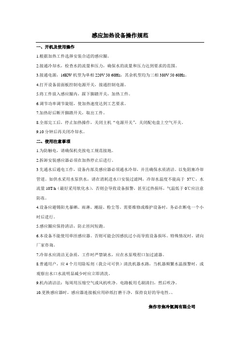
感应加热设备操作规范一、开机及使用操作1.根据加热工件选择安装合适的感应圈。
2.接通冷却水,检查水的流量和压力,确保水的流量和压力达到要求的范围。
3.接通电源,16KW机型为单相220V 50-60Hz,其余机型均为三相380V 50-60Hz。
4.打开设备前面板控制电源开关,接通控制电源。
5.将工件放入感应圈内,踩下脚踏开关,加热工件。
6.调节功率调节旋钮,使加热速度达到工艺要求。
7.加热好后断开脚踏开关,取出工件。
8.全部完工后,停止加热操作,关闭主机“电源开关”,关闭配电盘上空气开关。
9.10分钟后再关闭冷却水。
二、使用注意事项1.为防触电,请确保机壳按电工规范接地。
2.拆卸安装感应器必须在加热停止后进行。
3先通水后通电工作,设备内部及感应器必须通水冷却,并且确保水质清洁。
以免阻塞冷却管道。
如供水采用水泵供水,请在消耗进水口安装过滤网,冷却水温度不能高于37℃,水流量10T/h(最好采用软化水),否则会导致设备报警,甚至过热损坏,气温低于0℃应注意防冻。
4.设备应避锡阳光暴晒、雨淋、潮湿、粉尘等。
需要维修或维护设备时,务必在断电一个小时后进行。
5.感应圈应保持清洁,防止匝间短跑。
6.本设备不能使用单匝感应器。
否则可能会因感抗过小而导致设备损坏。
特殊情况时,请向厂家咨询。
7.冷却水应清洁无杂质,工作时严禁缺水,应在水泵吸程口加过滤器。
8.普通用户,应4个月用除垢剂(我公司可供)清洗机器水路,当机器频繁水温报警时,或观察出水口水流明显减少时应立即清洗。
9.机内清洁法:每周用压缩空气或风机吹净。
电路板用毛刷清扫,然后吹净。
10.更换感应器时,感应器连接板应用砂纸打磨干净,保持良好的导电性。
、焦作市焦冷氨阀有限公司。
高频感应加热机操作规程
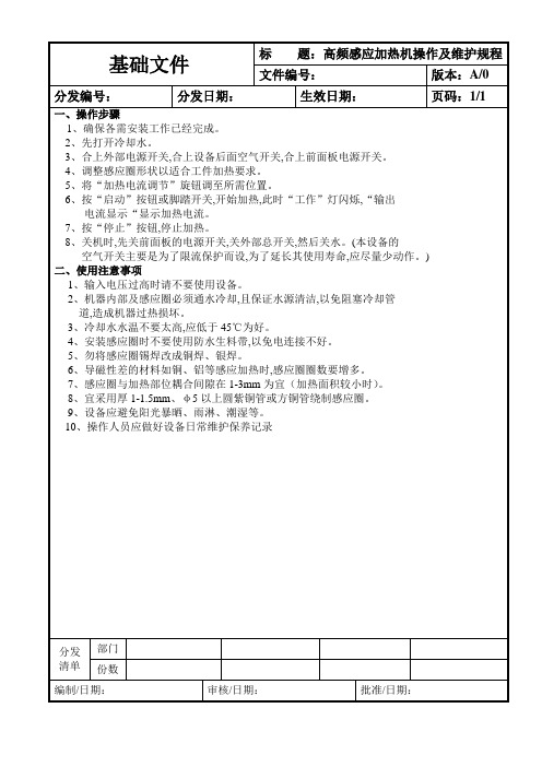
9、设备应避免阳光暴晒、雨淋、潮湿等。
10、操作人员应做好设备日常维护保养记录
分发清单
部门
份数
编制/日期:
审核/日期:
批准/日期:
2、机器内部及感应圈必须通水冷却,且保证水源清洁,以免阻塞冷却管
道,造成机器过热损坏。
3、冷却水水温不要太高,应低于45℃为好。
4、安装感应圈时不要使用防水生料带,以免电连接不好。
5、勿将感应圈锡焊改成铜焊、银焊。
6、导磁性差的材料如铜、铝等感应加热时,感应圈圈数要增多。
7、感应圈与加热部位耦合间隙在1-3mm为宜(加热面积较小时)。
6、按“启动”电流显示“显示加热电流。
7、按“停止”按钮,停止加热。
8、关机时,先关前面板的电源开关,关外部总开关,然后关水。(本设备的
空气开关主要是为了限流保护而设,为了延长其使用寿命,应尽量少动作。)
二、使用注意事项
1、输入电压过高时请不要使用设备。
基础文件
标题:高频感应加热机操作及维护规程
文件编号:
版本:A/0
分发编号:
分发日期:
生效日期:
页码:1/1
一、操作步骤
1、确保各需安装工作已经完成。
2、先打开冷却水。
3、合上外部电源开关,合上设备后面空气开关,合上前面板电源开关。
4、调整感应圈形状以适合工件加热要求。
5、将“加热电流调节”旋钮调至所需位置。
电磁感应加热器的制作方法

电磁感应加热器的制作方法一、引言电磁感应加热器是通过电磁感应原理实现加热的设备,它可以将电能转化为热能,广泛应用于工业生产和日常生活中。
本文将介绍电磁感应加热器的制作方法。
二、材料准备制作电磁感应加热器需要准备以下材料:1. 铜线:用于制作发电线圈;2. 铁芯:用于增强磁场;3. 电容器:用于储存电能;4. 散热器:用于散热;5. 控制电路:用于控制电磁感应加热器的工作。
三、制作过程1. 制作发电线圈:将铜线绕在一个绝缘材料上,绕成线圈状。
线圈的大小和形状可以根据具体需求进行设计。
绕好线圈后,将线圈两端的铜线固定好,确保其不松动。
2. 安装铁芯:将制作好的发电线圈放入铁芯中。
铁芯可以是一个铁环,也可以是其他形状的铁块。
铁芯的作用是增强磁场,提高电磁感应加热器的效果。
3. 连接电容器:将电容器与发电线圈连接起来。
电容器可以储存电能,使电磁感应加热器在供电中断时仍能继续工作。
4. 安装散热器:将散热器安装在电磁感应加热器的发电线圈和电容器附近,用于散热。
由于电磁感应加热器在工作过程中会产生一定的热量,散热器的存在可以有效降低设备的温度,保证其正常运行。
5. 连接控制电路:将控制电路与发电线圈和电容器连接起来。
控制电路可以根据需要设计,用于控制电磁感应加热器的工作状态和加热功率。
四、工作原理电磁感应加热器的工作原理是利用电磁感应现象,即当导体在磁场中运动时,会产生感应电动势,从而产生感应电流,进而产生热能。
具体来说,当电磁感应加热器通电后,发电线圈中的电流会产生磁场,磁场会使铁芯磁化,进而产生感应电流。
感应电流在发电线圈中流动时,会产生磁场,磁场的变化又会产生感应电流,如此循环往复,最终导致发电线圈中的电能转化为热能。
五、应用领域电磁感应加热器广泛应用于工业生产和日常生活中。
在工业生产中,它可以用于金属加热、熔化、焊接等工艺;在日常生活中,它可以用于电磁炉、电热水壶等家电产品中。
六、总结通过制作电磁感应加热器,我们可以将电能有效地转化为热能,实现加热的目的。
单相3KW电磁加热器使用说明书

F-19
F-20
F-22
0
0
0
显示输入电流值(出厂默认)
1
0
0
显示热敏电阻测量温度 0-150℃,通过 F-16 和 F-17 来设置控
制温度
2
0
0
显示热敏电偶测量温度 0-500℃,通过 F-16 和 F-17 来设置控
制温度
3
0
0
显示热敏电偶测量温度 0-1000℃,通过 F-16 和 F-17 来设置
7:触摸屏带外接时钟工作模式
8:电磁采暖炉数码彩屏工作模式
9:商用电磁炉工作模式
F-21 外 接 电 位 器 或 外 5-250
0
接 PID 调节功能
关断多功能电压
设置
F-22 PID 设 置 功 能 和 0:通用加热
0
F-19 配合使用
1:外接电位器调节功率,(最大功率
受 F-01 限制)
2:当 F-19 为 2 时,可实现 0-500℃
保护功能动作后,请处理引起的原因后,电磁加热器断电再重新上电,然后开始运转。
出错(报警)定义:
代码 A-01
A-02
A-03
代码 E-01
E-02 E-03 E-04
E-05 E-06 E-07 E-08 EnD
运行警告(仍可继续工作,但必须调整)
描述
原因及排查
线圈离负载距离较远
保温棉过厚、线圈每圈与每圈
减小试试 线圈短路、瞬间电流过大 IGBT 传感器断开或没插好 散热器温度过高、风扇不转或
堵塞、 制定功能才有 制定功能才有 输入或输出电流过大保护 线圈电感量过小 需在 F-14 功能输入密码方可
状态为 15kHz 左右。
三相全桥电磁感应加热器使用手册
甚至会损坏电磁加热器。 请按本手册的内容和注意事项正确使用电磁加热器。 (连 接外部设备,请参考相关手册)
名称 电源
说明 请使用在电磁加热器的允许规格内的电源,常 规为AC380V。
漏电断路器 (ELB)或无熔丝 断路器(NFB) 电磁接触器
由于在电源投入时,电磁加热器会流入很大的 冲击电流,故必须注意断路器的选定。
JONSON
江信电磁感应加热电源
JS1000 系列产品
使用手册
专业工业、商业、民用等设备高效加热
佛山市顺德区江信电子制造限公司
非常感谢您选择广东江信电磁感应加热电源。 本手册为 JS1000 系列产品,包括全桥 5-80KW/380V 电磁加热控制器、控制板、控制柜系列 产品,使用时的操作说明和注意事项。 不正确的使用可能会发生意想不到的事故。 使用本产品前, 请仔细阅读本手册并正确地使用 本产品。
安全事项 1.防止触电 危 险
●在通电或运行时请不要打开盖板,否则发生触电。 ●布线或检查请断开电源十分钟以后,用万用表测量剩余电压后进行。 ●电磁加热器外壳请接地,以免高频感应电压触及人身。 ●包括布线或检查工作在内的工作都应是专业人员。 ●请不要湿手操作开关电源,以免造成触电或受伤。 ●对于电缆(包括高频输出电缆)请不要损伤它,对它加上过重的应力。否则造成触电。 ●请勿在通电中进行通风扇的清理或更换,否则造成伤害。 ●人身远离高频输出端口及电源输入端口。
2.防止火灾 注 意
●电磁加热器请安装在不可燃物体上,直接安装在易燃或靠近易燃物品,会导致火灾。 ●电磁加热器发生故障,请断开电源,若持续地流过大电流可能会导致火灾。 ●高频输出线圈请勿短路,可能会引起火灾。
3.防止损伤 注 意
●请按照规定的额定电压提供给电磁加热器,以防止爆裂、损坏等等。 ●确认输出线圈与电源正确的端子连接,否则会造成爆裂、损害现象。
- 1、下载文档前请自行甄别文档内容的完整性,平台不提供额外的编辑、内容补充、找答案等附加服务。
- 2、"仅部分预览"的文档,不可在线预览部分如存在完整性等问题,可反馈申请退款(可完整预览的文档不适用该条件!)。
- 3、如文档侵犯您的权益,请联系客服反馈,我们会尽快为您处理(人工客服工作时间:9:00-18:30)。
感应加热器教程 3kwInduction Heater TutorialAn induction heater is an interesting device, allowing one to rapidly 迅速的 heat a metal object. With enough power, one can even甚至 melt 熔化 metal. The induction heater works without the need for fossil化石 fuels, and can anneal退火 and heat objects of various各种各样 shapes 形状. I set out to make an induction heater that could melt steel and aluminum. So far迄今为止 I have been able to feed an input power of over 3 kilowatts! Now that I have done this I would like to share how it works, and how you can build one. At the end of the tutorial I will discuss 论述 and show you how to build a levitation coil that will allow you to boil煮沸 metals while suspended in mid air! 一台感应加热器是一台有趣的设备,可以迅速加热金属工件.功率够高时,可以融化金属.感应加热器不需要石化燃料,可以对工件退火处理,还可以加热各种形状的工件.我制造了一台可以融化钢和铝的感应加热器.现在功率已经达到了3千瓦!我来教你怎么造一台.在教程的最后,我将教你造一个可以在半空中融化金属的磁悬浮加热线圈. My induction heater is an inverter. An inverter takes a DC power source and converts it into AC power. The AC power drives a transformer which is coupled耦合 to a series LC tank. The inverter frequency is set to the tank's resonant共振 frequency, allowing the generation of very (high currents高安培电流) within the tank's coil. The coil is coupled to the workpiece工件 and sets up (eddy currents涡电流). These currents, traveling through a conductive, but slightly微小 resistive电阻的workpiece, heat the piece. Remember, Power = Heat = R*I^2. The workpiece is like a one-turn coil; the work coils has several数个 turns圈. Thus 这样, we have a (step-down transformer降压器), so even higher currents are generated in the workpiece.这样电流就流进工件里去了. 我的感应加热器有一个逆变器.逆变器可以把直流电转换为交流电.交流电被变压器耦合到感应线圈和电容组一起组成的振荡器上.逆变器的工作频率决定振荡器的振荡频率.振荡器的感应线圈会感应出非常大的电流.感应线圈又将这些电流产生的磁场耦合到工件上产生涡流电.工件中的电阻,阻碍涡流电的流动,导致工件发热.(详细原理参照变压器中的涡流电).记住,功率=热=R乘以I的平方.工件可以看成一个只有一圈的线圈,而感应线圈有多个线圈,这样一来就可以把感应线圈和工件看成一个变压器回路,工件的电压低,电流就从感应线圈流向工件去了.I would like to acknowledge鸣谢 the invaluable无法估计的 help from John Dearmond and Tim Williams for helping me understand this topic话题. Now, before we talk more, let's see some pictures of what it can do. 谢谢 John Dearmond 和 Tim William大量的帮助,帮我弄明白这个话题.先来看几张图.Later, I will give a link to a video showing it running. Here is the inverter. 下图是逆变器:What I will now do is go over each part. Then, I will give the schematics 电路图, go over them and how you can build this device. 我将介绍每一个部分.然后给出电路图.然后你就明白怎么造了.Induction Heater Components 感应加热器的组成部分We will talk about each component部分( making up组成) the induction heater. First, there is the workcoil. This is what heats the workpiece. The workcoil will get very hot from the high current going through it and the radiation of heat from the workpiece. 我们将讨论感应加热器的零件话题.首先是感应线圈, 它有高压电流,被加热的工件会将热回传到感应线圈上. The workcoil is attached to the LC tank. This can either be a series or parallel (resonant tank谐振回路). The tank and coil need to be cool, so I implemented a plumbing水管装置-type design that allows me to pump water through the coil using a fountain喷水 pump. 感应线圈与电容组组成振荡器.它可以是串联振荡器也可以是并联振荡器.我搞了个泵抽水来冷却电容组和感应线圈. The resonant tank is coupled to the power source with a (coupling transformer耦合变压器). The transformer is connected to the inverter. 谐振回路靠耦合变压器来与逆变器相连. The inverter chops the DC power source at a particular特定的 frequency. This is the (resonant frequency 谐振频率) of the tank. Now, as the workpiece heats and goes through its (curie point居里温度点) - the temperature when the metal is no longer ferromagnetic - the resonant frequency changes. The inverter needs to stay locked on as closely as possible to the current resonant frequency to achieve获得 the fullest power. Some will do this manually手动, using an oscilloscope示波器 to monitor the waveforms, or using a voltmeter伏特计 on the tank and tuning the frequency to the highest tank voltage. Another method is using a phase locked loop (PLL) to monitor the (phase relationship相位关系) of the inverter voltage and tank voltage. This is the method I use and I will discuss论述 this in detail later on. 逆变器将直流电转换成交流电的频率是振荡器的谐振频率.工件温度升高并穿过居里点,本身特有磁性消失,会改变振荡器的谐振频率.逆变器必须将直交流变换频率锁定在当前振荡器的谐振频率以获得最大功率.这项工作可以手工进行,用示波器和电压表对振荡器的波形和电压调整来调谐振荡频率以获得振荡器最大工作电压.另一种方法是用锁相环通过相位关系来控制逆变器和振荡器的电压.这种方法等会儿说. Let's start with how to easily make a workcoil. We will be using frequencies in the 10s to 100s of kilohertz (kHz), so metals will conduct传导 the current only slightly (below the surface深入). This is the (skin effect趋肤效应). The current depth深度 in mm is 先来做个感应线圈.频率范围10khz~100khz.电流透入工件的深度有趋肤效应用下式计算. Depth (mm) = 76/√(F) 深度(毫米)=76除以根号(频率) So, the wider the tubing, the lower the resistance. We also want to use tubing so we can water-cool the coil. I purchased购买 some refrigerator水箱 3/8" copper tubing from Home Depot. You will also need some 1/2" copper pipe and the necessary fittings配件 so you can feed water through one end,have it circulate循环 through the coil, and come out the other end. Ihave (brass fittings黄酮配件) with nipples接头 so I can attach some tubing to my fountain pump, and a return tube to my ice water bath. 大铜管小电阻.铜管可以水冷.我从五金商店买了些3/8''的铜管.你还要买些1/2''的铜管,和铜接头,把它们焊在一起连上泵,就能让水循环了. This is the tubing I got from Home Depot. 铜管.LC Tank: (Polypropylene Film Capacitor Bank聚丙烯薄膜电容器组) 振荡器The induction heater uses a workcoil as a step-down transformer. This transformer steps the voltage down, but increases增大 the available可用的 current to the workpiece, which is the one-turn coil that completes the transformer. The (magnetic flux磁通量) is coupled to our workpiece. The better the coupling, the more efficient效率高的 is our workcoil. The closer the workpiece is to the coil the better the energy transfer. 感应线圈是个变压器,工件的电压低,电流都往工件跑,工件是个一圈的感应线圈,电流以电磁的形式耦合到工件.好的耦合,高的效率,就是我们的线圈.工件与线圈越近能量传送效率越高. This is the workcoil and tank. The capacitors are high voltage metallized power film snubbers. 下面是线圈,还有这些电容器是高压金属化薄膜功率缓冲器.The workcoil is made from shaping the 3/8" copper tubing. I use brass compression fittings to attach it to the LC tank. The tank is made fromtwo 1" x 3/16" thick厚 copper bars. I drill holes in the bars to accommodate容纳 the capacitors. We need a capacitor that can handle several hundreds of amps安培 of current. I purchased购买 some (pulse capacitors脉冲电容) with (current ratings现行定额) of 14A, 3000vdc, 750vac. With 20 capacitors this is close to 300A average平均 current. The coupling transformer (fits over安上) the copper tubing. If you look closely, you will see the fountain pump submerged淹没的 in water. This pumps ice water through the tank and back out into the bucket. Water flows in from the bottom left, through the copper pipe soldered to the bus bar, through the coil, over the bank to the upper left, and through the tubing connected to the other bus bar, and out on theupper right. You should also take note where the workcoil connects with the capacitor bank. (It does not connect both leads at the front end; instead不是连结每个头在最前端), the coil connects to (opposite ends相反一头的前端). This ensures确保 that the capacitors share an equal 相等 (current load海量电流). Otherwise否则, if both end connected to the front, the capacitors closest to the coil would handle the brunt冲击力 of current because the resistance would be the least. When you are dealing with hundreds of amps, small changes in R are significant重要的. 用3/8''的铜管做线圈.用铜接头把它和电容组连接.电容组用两条1X3/16''厚的铜板固定.铜板上打了洞来放电容.我们需要能通过数安培电流的电容.我买了些高压脉冲电容,参数是14A,3000VDC,750AC.20个电容,这样就差不多能承载300A电流.耦合变压器安在铜管上.近看,泵在水里.泵把水泵过电容组和铜管,水再回到水桶里.水从左下进,右上出.你要注意线圈怎么和电容组连接的.线圈和电容组是不对称连接的,看上图.有耦合变压器(黑陀陀)的那条铜管,它是转了个弯才和线圈连接的.这样做是为了保护靠近线圈的电容,可以使电流平均的承栽到电容上.如电容不迂回连接,靠近线圈的电容的电阻最小,会过流大电流而烧毁.当你使用数百安培的电流时,你得注意电阻稍微改变的后果.These are the bars with the holes drilled in them. The tank uses 20capacitors, but you can use any number that gives you the capacitance and current handling capacity that you require. 打了洞的铜条.可以安20个电容.,你可以自行决定电容的数量,和电流大小.First, you need to determine决定 what operating工作的 frequency you will use. Higher frequencies have greater skin effect (less penetration穿透) and are good for smaller objects. Lower frequencies are better for larger objects and have greater penetration. Higher frequencies have greater (switching losses开关损耗), but there is less current going through the tank. I choose a frequency near 70khz and wound up with about 66khz. My capacitor bank is 4.4uf and can handle over 300A. My coil is near 1uH. The capacitors are from Illinois Capacitors. Mine are0.22uf/3000vdc. The model number is 224PPA302KS. 你先得决定机器的工作频率.高频率对工件的穿透能力低适合加工小物件.低频率相反.高频率有大的开关损耗.但穿过电容组的电流小.我选择70KHZ到66KHZ之间.我的电容组的电容量是4.4微法可以通300多安电流.我的线圈的电感量是1微亨.电容的生产厂是Illinois Capacitors.每个的参数都是0.22uf/3000vdc.型号是224PPA302KS. Fres = 1/2π√(LC) 频率=1除2乘以派乘以根号(电感量乘以电容量) Once you wind卷绕 your coil you can get an idea of its value by making a simple RLC circuit with it and connect it to a (function generator 函数信号发生器) and scope. I used a 1R resistor and a 500pf capacitor.I increased增强 my function generator sine wave and measured the voltage across R(R两端的电压). At resonance the LC (impedance drops阻抗降) and the voltage drop across R peaks达到峰值. This gave me a ballpark大致正确的 figure计算, but you can just go by the calculation估计. 线圈的电感量可以用简单的RLC电路,联上函数信号发生器来确定.我用1欧电阻和500皮法电容.我增强函数信号发生器发出的正弦波然后量电阻两端的电压降.谐振时LC的阻抗变低,R两端电压变(可能高也可能低,得看怎么连接了). Now, as far as the workcoil goes you can form the workcoil by driving a piece of PVC tubing into the ground. I used a 1" pipe (1.5" OD).( Take the copper tubing and fill it with sand or salt在铜管里装满沙或者盐). Make sure it is completely filled填满的. This way it will act like a solid实心的 tube and will not collapse塌陷 when you bend弯曲 it. Fix one end with something like a heavy vice and work the tubing around your PVC tube until you have your desired渴望的 number of turns. Four to five turns at 1.5-2" will give you a coil with an inductance感应系数 between 0.8 - 1.3 uH. 用PVC管来饶线圈,把一根1.5''外径( outer diameter)的PVC管插在地上.在铜管里装满沙或盐.确定填满.实心的铜管绕时不会扁.把铜管绕在PVC管上,你想绕几圈就绕几圈.绕4~5圈就可以有0.8~1.3微亨的电感量.You can see how nicely令人满意的 the coil forms around the pipe. Once you are happy with the turns and shape you can blow the sand out with an air compressor.你可以绕个你爱的线圈.绕好后把沙或盐用压缩机吹出来.Power Supply: Voltage double and regulated source 电源:倍压和稳压电源I need to talk about two power supplies for the unit. One is the high voltage DC that the inverter converts to AC for feeding the tank. You need an unregulated未调制的, smoothed平滑 source. You can use 110vac througha rectifier整流器 and smoothed with a 1000uf-1500uf capacitor for a supply of 170vdc. I used a (voltage multiplier倍压器) to convert it to 320vdc. Below are some basic schematics for a (voltage doubler倍压器).I used the third variation变种 for mine. Make sure you have your rectifier on a large (heat sink散热片) because it will be conducting a lot of amperes. My rectifier is rated for 25A/500vac. 给逆变器供电,我用第三张图的,整流器要求25A/500VAC.电容1000~1500微法.第三张图的过程是,整流,倍压,再到逆变器.The second power supply you will need will be a 15vdc regulated控制 source. It is imperitive that it is regulated because the PLL has a (voltage controlled oscillator压控振荡器). The VCO determines the output frequency based on input voltage it receives. The frequency range it can generate is based on its supply voltage, Vss. If the supply voltage wanders 迷失, the oscillator frequency will wander and this will definitely肯定的 throw you out of resonance. 给锁相环供电,要求可以控制电压的电源,最大15伏.锁相环的输出频率是基与输入电压的.频率变化范围是基于电源电压的,如果电源电压错乱,振荡频率肯定也错乱.RCL Theory理论 and (Transformer Coupling耦合) RCL理论和变压器耦合I guess the best way to understand what is going on is to start with the wor kcoil and work backwards. Remember from earlier I said that the workcoil is the (primary end初级的一端) of a step-down transformer. We have hundreds of amps flowing through here and this creates产生 a voltage in the workpiece. We achieve获得 these high currents because the RCL tank is at resonance. This means that the (inductive reactance感抗) and (capacitive reactance容抗)( cancel out抵消), and all we are left with is the small, real resistance. 解析加热线圈的工作的背后的原理.我说过工件和加热线圈组成一个变压器回路,加热线圈看成是初级,工件是次级,电流流过初级,次级产生感应电压.RCL在谐振时我们获得大电流.前一句的意思是感抗容抗抵消,只剩电阻的阻值无法抵消. Below we have a RCL circuit with a resistance of 4R, Zl = 4ohms and Cl = 3ohms. The reactive反应 impedance 阻抗 cancels抵消 to 1ohm, giving us a phase shift of 18degrees leading. The inductor wins and the inductor voltage leads the current. There is only one current running through the series circuit. You can also say the inductor voltage leads the voltage across the resistor, because the voltage and current of the resistor are (in phase同相). Remember, the voltage drop across an inductor is a reaction反作用力 against抵抗 a change in current through it. The( instantaneous voltage瞬时电压) is zero when the current is at a peak because the change in current is zero, (manifested by the zero slope表现在零坡度). 下图表示一个RCL电路,电阻4欧,感抗4欧,容抗3欧.电路启动后阻抗抵消,剩1欧,得到一个相位超前18度角的波.电感的感抗没和容抗抵消完,导致电感的电压的波的相位超前电流的波的相位.这里只有一种电流.你可以说电感的电压的波的相位超前电阻两端的电压的波的相位.电阻的电压和电流的波的相位是同相.电感因为电磁感应的一些原因,它两端的电压会阻碍交流电流穿过.当电流达到最大值时,顺时电压为0,因为电流还未变化.下图的部分表示前一句话的图解.If the inductive and capacitive reactance cancel out the phase shift is zero. The current in the circuit is in phase with the voltage. 电感的电抗和电容的电抗抵消,电流与电压的波的相位是同相.Now here is an important point. The maximum power transfer传输 will occur 发生 when the current is in phase with the voltage. 上图意思电流和电压的波同相位,得到最大功率. So, at resonance, the current in the series circuit is in phase with the voltage source. If we are out of resonance( the current phase is shifted from zero with respect to the voltage电流相位和电压相位将错开). If there is more inductive reactance the (currentlags the voltage电流相位滞后于电压相位); if there is more capacitive reactance the (current leads the voltage电流相位超前于电压相位). You can also say the capacitor voltage lags the current. 在串联电路里,谐振时电流和电压源的波的相位相同.如果失谐,电流的波的相位和电压的波的相位将错开.感抗多,电流的波的相位滞后与电压的.容抗多,电流的波的相位超前与电压的.你可以直接说电容电压滞后与电流. What is the voltage source for the series tank It is our (coupling transformer耦合变压器). I am experimenting with different materials and turns圈数, but right now I am using an iron powered core from Amidon Corp made from Type 3 material. This material is good from frequencies between 0.05Mhz and 0.5Mhz. I used two toroids环形的. Each is 2.25" in diameter直径 and 0.565" thick. I wound 14g wire around for 20-26 turns. I am still trying to (figure out 弄明白) the optimum最适宜的 turns and the best material. The( lower the turns减少圈数) the( greater greater the exciting voltage励磁电压越大) to the tank. However, magnetization current goes up as does the load on the inverter逆变器开始负载电磁流. 给振荡器供电的是谁呢是耦合变压器.我用不同的材料和不同的线圈圈数实验耦合变压器,我现在用的是Amidon Corp 的3型铁芯磁环.支持的频率是0.05MHZ~0.5MHZ.我用两个每个直径2.25''厚度0.565''.我用14号(gauge)规格的电线绕20~26圈.我试了很多次才确定绕线的圈数和铁芯材料.减少偶合变压器饶线的圈数,到振荡器的感应电压越大.不管怎么样,逆变器开始工作了. Below are the two toroids. I use two to (prevent saturation防止饱和). I wonder how three would do 下图两磁环.我用两个是为防止饱和.不知用三个怎么样.Here I have wound 14g wire around. The transformer does not impart告知 (a phase shift if place on the tank correctly相移在磁环上恰当). If you (flip it around胡绕) you will introduce a 180 degree shift which will prevent 阻止the PLL from locking onto the frequency. Just turn it around. Which way is the right way Use the right-hand rule. 我用14号线绕.不能胡绕,胡绕锁相环就失控了.那该怎么绕呢用右手法则.Here is a solenoid螺线管 with the current flowing in the direction shown. Put your right thumb拇指 in the direction of the current and your fingers curl卷曲 in the direction of the B field(假装右手拿了一个透明玻璃杯的样子,不包括拇指). The field outside of the coil is not important to us; the field inside the solenoid sums to one large field going from right to left. If we had a metal bar or part of the toroid圆的's arc弧形物inside, the field场 would travel through it. 下图红色箭头是电流,黑线是电线,右手拇指指向红色箭头的方向,其他四指半弯曲,指向头上有小箭头的字母B.电磁场就从你的手掌穿过,电流的方向是拇指指的方向,磁场的方向是其它四指指的方向.So here is a (mock-up教学模型) of the coupling transformer. The current travels to the (positive terminal正极) of our toroid环形 transformer output. Using the right hand rule we can realize实现 the direction of the B field for each turn. The black arrow on the toroid shows the direction the field travels in the core. Using the right-hand rule again we see that the current travels through the copper tubing from left to right towards 朝 the positive terminal of our RLC tank. We will use this as the positive 正极 lead for monitoring our tank capacitor voltage later. If you are unsure which end is which you can wind卷绕 a few turns of wire as a secondary and scope区分范围 the ends如果你不确定是哪一端,你可以随便卷绕几圈来确定是哪一端. The voltages in and out should be in phase. 下图是一个耦合变压器的简单模型.图中黑色的电线,电流就是打+号(正极)流过黑电线绕成的线圈,从-号(负级)流出.现在我们知道了电流方向,用右手定则来确定磁场方向,图中白环上有一个黑箭头,那就是磁场方向,磁场在磁环的肚子里.图中黄灿灿的铜管会感应到耦合变压器产生的磁场,而产生感应电压,电流又会从+到-.流过铜管流到振荡线圈.Oscilloscope Tracings追踪示波The inverter outputs a drive voltage to the coupling transformer. The current in is in phase with the current out. When the tank is at resonance, the tank current is in phase with the drive current of the coupling transformer, and is in phase with the inverter input voltage. If anything, you want the current to slightly lag the voltage because the mosfets 金属氧化物半导体场效应晶体管 behave表现 better when facing an inductive感应的, (rather than a capacitive而不是一个电容), load. This has to do with the mosfets conducting in the (reverse direction反向). The tracing below is clean and allows me to reach到达 very high power levels while maintaining relatively cool mosfets同时保持相对的冷. 逆变器输出一个驱动电压到耦合变压器.电流全程同相.当振荡器谐振,振荡器电流和耦合变压器电流同相还有逆变器输入电压.如果你想电流滞后电压,那么场效应管比电容效果好,特别是在感抗高的时候.上机.场效应管用反向导通.下图显示没有杂波,我可以用大功,率场效应管还不烫.Now, if the tanks (is above超出...之外) resonance we have more inductive reactance. The tank's net current will lag the (driving voltage励磁电压) from the coupling transformer. Since the input and output current of the coupling transformer are in phase, the tank's current is lagging the inverter driving voltage. Below you can see the dominating inductive reactance results in the inverter current (trianglelooking wave) is almost 90 degrees lagging the inverter voltage (square wave). 如果高于谐振频率,感抗变大.振荡器的电流滞后于耦合变压器传来的感应电压.由于耦合变压器的输入输出电流同相,振荡器的电流也滞后于逆变器的电压.下图,感抗高的结果是逆变器电流(三角波)差不多滞后逆变器电压90度角(方波).If we are below低于 the resonant frequency capacitive reactance results in the current leading the inverter voltage. Also, there is ringing振铃波 in the current waveform and at the inverter voltage transitions. This noise gets worse with higher power levels and can result in mosfet failure. 低于谐振频率,容抗变大,结果电流超前逆变器电压.下图有些振铃波在电流波形和逆变器电压波形上.这些噪声在大功率时更糟,还会使场效应管损坏.I would like just mention提及 that the inductive waveforms is really an (exponential curve指数). If we can approximate近似的 the tank above resonant as a RL circuit (responding to回答) a (step response阶跃响应) 我还想提一下,电感性波形是一个指数曲线.我们可以RL电路响应跃阶响应来模拟振荡器谐振.The solution解答 toOscilloscope Tracings II 示波 IILet's continue our discussion讨论 of oscilloscope tracings so we can better understand how the inverter is going to work and lock onto resonance. From the last page I mentioned提及 that voltage across the tank capacitor lags the current by 90 degrees. At resonance, the tank current has a zero phase shift with respect to source (inverter) tank voltage because the inductive and capacitive reactance cancel out. If you display the invertervoltage and capacitor voltage together, you can see the sinusoidal正弦曲线 capacitor voltage lags the inverter voltage by 90 degrees. The square wave is the inverter voltage, but you would get the same relationship关联 if you scoped the voltage output of the toroid transformer. 继续弄明白逆变器和锁相环怎么工作.上页说到振荡器的电容电压滞后电流90度.谐振时振荡器电流与逆变器和振荡器自己的电压是同相.下图,如果你把逆变器电压和电容电压放在一起观察,电容电压波是正弦曲线,滞后逆变器电压90度.方波是逆变器电压,你监测耦合变压器的输出电压,就可以得到一些关联.We will monitor this relationship. We are at resonance when our PLL chip keeps Vc ninety90 degrees lagging behind Vinverter. Now, we can easily exceed超过 the chips maximum input voltage, so we need to clip修剪 the top and the bottom the capacitor voltage, and keep it to a maximum of 15v. We do this with some clamping钳位 diodes二极管 yeilding捕获 this waveform, which will be the signalin input on pin 14 of the HEF4046锁相环芯片. 我们来看这些联系.谐振时锁相环保持电容电压滞后于逆变器电压90度.这样很容易超过锁相环芯片的输入电压,我们需要电容电压维持在最大15V,我们用钳位2极管钳位电容的波的电压,再输入进HEF4046的第14脚.Below is a diagram图解 of the scoped voltages. Using a (differential probe差分探头), the positive lead goes to the positive inverter lead going to the toroid and the negative to the negative lead. Using a second differential probe we scope区分 the + and - ends端 of the capacitor tank. Vc will lag Vinv or Vtank. We will have to invert使反转 the Vc waveform, that is shift it 180 degrees, (in order合乎程序的) for the PLL to work, which I will discuss shortly. 下图解释监测电压.用差分探头,正极插到逆变器和耦合变压器正极之间,负极到负极.第2个差分探头到电容,我们得注意电容的正负极.VC滞后VINV或VTANK.我们反转VC的波形,相移180度,进锁相环工作.Now, we are ready to talk about the phase locked loop chip - the HEF4046. After this discussion, we will have enough information to understand the workings of the inverter and how it maintains保持 a lock on the resonance. 该说锁相环HEF4046了.说完锁相环还有逆变器如何维持谐振.Phase Locked Loop (PLL) Basics基本原理锁相环的基本原理When you read about induction heaters and inverters you will probably (come across遇到) the term术语 phase locked loop. The people writing the tutorials will assume假装 you know all about these. I will make the opposite assumption and give you a brief understanding of the concept so you can understand how this will help maintain resonance with our induction heater.我将作出相反的假设,并给您一个简单的概念,以便你能理解这将如何帮助我们维持感应加热器的振荡. 一个你可能不清楚的术语,锁相环.别的教程都假装你懂.我将作出相反的假设,并给您一个简单的概念,以便你能理解这将如何帮助我们维持感应加热器的振荡. A PLL (consists of由...组成) three parts: a voltage controlled oscillator (VCO), a (loop filter环路滤波器LPF) and a (phase detector鉴相器PD). The VCOout drives the device, or (inverter gate反向门) in our case. It also closes the loop by feeding itself back into the phase detector so it can get (compared with与...相比) a (reference signal参考信号). PPL由3部分组成:压控振荡器VCO.环路滤波器.鉴相器.VCOout用来驱动某些设备或反向门.下图,VCO用个环来将输入输出信号进行比较.The VCO generates a 50% (duty cycle占空因数) square wave; the frequency depends on the input voltage to the VCO. The higher the VCOinput (pin 9) voltage the higher the VCOoutput frequency; the lower the voltage the lower the frequency. The PLL phase detector compares the phases of two inputs: the reference signal on pin 14 and the VCOout frequency. The phase detector has two options for outputs: PCA1 and PCA2. We use the former 前者, which is a XOR异或 gate. VCO发出50%占空比的方波,频率由输入电压决定.VCO的第9脚如果输入高电压,VCO的输出频率就高,反之输出频率低.PD比较相位用两个脚,参考信号在14脚,和VCOOUT脚输出频率.PD还有2个选项PCA1和PCA2.我门用前者异或门.The logic is high if one of the two inputs is high; otherwise it is low. It will generate a square wave (whose width is based on其宽度是根据) the (phase difference相位差) of the two signals. If the two waves are 90 degrees out of phase the (average value平均值) of Vphi is Vdd/2. The loop filter takes the phase detector output and converts this to the input voltage to the VCO. The simplest filter is a RC low-pass filter. The (cut-off frequency截至频率) will determine判定 how sensitive the PLL is to phase changes, and how well it stays locked on the reference signal. 异或门,输入两个信号,其中一个高,输出就高,如果不是,输出都低.我将产生一个方波,脉宽根据相位差决定.如果被比较的两个波相位差90度,(PD)比较后的电压VPHI差不多是芯片的工作电压VDD的2分之1.LPF又将VPHI转换成一个输入电压到VCO,兼输出.LPF是一个RC低通滤波器.截止频率将判断PPL相位什么时候改变,什么时候锁住谐振信号. So what happens At resonance the tank current is real and in phase with the coupler transformer voltage, which is in phase with the inverter voltage. The tank capacitor voltage lags the tank current by 90 degrees; therefore由此得出, it lags the inverter voltage by 90 degrees. Now as the workpiece heats its ferromagnetic铁磁体 properties性质 change. The workcoil becomes变成 a (variable inductor可变电感线圈) and affects影响 the resonant frequency of the tank. If the effective事实上的 resonance goes down, it seems好像 to the circuit that we increased增强 on drive frequency to the tank. This makes the tank more inductive. Inductance causes the source voltage lead the tank current. That is, the tank current is forced to lag the inverter voltage. The capacitor voltage initially lagged the current by 90 degrees. This means the capacitor voltage lags the inverter voltage even more as shown below.这意味着电容电压滞后于逆变器电压更甚,如下所示. 谐振时,振荡器的电流和耦合变压器的电压同相,还有逆变器的电压.振荡器的电容电压滞后于振荡器电流90度.由此看来,它也落后逆变器电压90度.工件受热后,它的铁磁性质发生了改变.加热线圈成了一个可变电感线圈.这种变化影响了振荡器的谐振频率.如果振荡器停机,可能是我们的电路给振荡器提高了频率..电感变大了.会导致振荡器电流强制滞后于逆变器电压.电容电压开始就滞后于电流90度.这意味着电容电压滞后于逆变器电压更甚,如下所示.Below we can see the relationships关系 with Vinv, Vcap and Vphi. Vphi is high Vinv or Vcap is high, but not both. 下面是VINV逆变器电压,VCAP 电容电压,VPHI(PD)比较后的电压,的关系.vphi高,VINV或VCAP就高,但不是同时三个一起高.。