华为交换机聚合端口配置实例
华为交换机VLAN聚合(超级vlan)配置示例
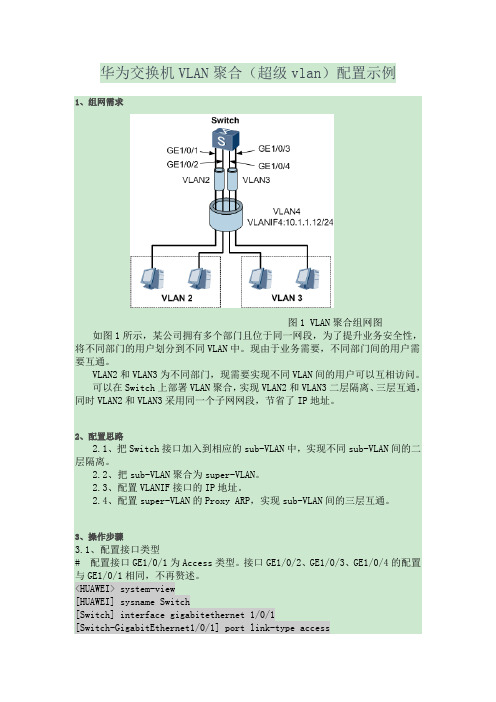
华为交换机VLAN聚合(超级vlan)配置示例1、组网需求图1 VLAN聚合组网图如图1所示,某公司拥有多个部门且位于同一网段,为了提升业务安全性,将不同部门的用户划分到不同VLAN中。
现由于业务需要,不同部门间的用户需要互通。
VLAN2和VLAN3为不同部门,现需要实现不同VLAN间的用户可以互相访问。
可以在Switch上部署VLAN聚合,实现VLAN2和VLAN3二层隔离、三层互通,同时VLAN2和VLAN3采用同一个子网网段,节省了IP地址。
2、配置思路2.1、把Switch接口加入到相应的sub-VLAN中,实现不同sub-VLAN间的二层隔离。
2.2、把sub-VLAN聚合为super-VLAN。
2.3、配置VLANIF接口的IP地址。
2.4、配置super-VLAN的Proxy ARP,实现sub-VLAN间的三层互通。
3、操作步骤3.1、配置接口类型# 配置接口GE1/0/1为Access类型。
接口GE1/0/2、GE1/0/3、GE1/0/4的配置与GE1/0/1相同,不再赘述。
<HUAWEI> system-view[HUAWEI] sysname Switch[Switch] interface gigabitethernet 1/0/1[Switch-GigabitEthernet1/0/1] port link-type access[Switch-GigabitEthernet1/0/1] quit#创建VLAN2并向VLAN2中加入GE1/0/1和GE1/0/2。
[Switch] vlan 2[Switch-vlan2] port gigabitethernet 1/0/1 1/0/2[Switch-vlan2] quit#创建VLAN3并向VLAN3中加入GE1/0/3和GE1/0/4。
[Switch] vlan 3[Switch-vlan3] port gigabitethernet 1/0/3 1/0/4[Switch-vlan3] quit3.2、配置VLAN4# 配置super-VLAN。
华为交换机两种端口聚合模式使用实例
2.5 配置举例介绍了两种模式下的典型应用场景举例。
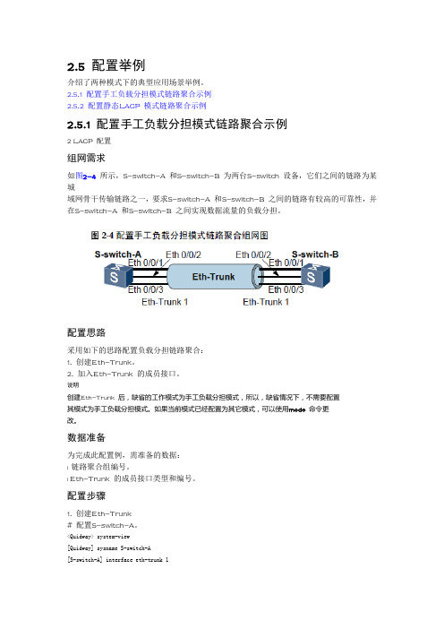
2.5.1 配置手工负载分担模式链路聚合示例2.5.2 配置静态LACP 模式链路聚合示例2.5.1 配置手工负载分担模式链路聚合示例2 LACP 配置组网需求如图2-4 所示,S-switch-A 和S-switch-B 为两台S-switch 设备,它们之间的链路为某城域网骨干传输链路之一,要求S-switch-A 和S-switch-B 之间的链路有较高的可靠性,并在S-switch-A 和S-switch-B 之间实现数据流量的负载分担。
配置思路采用如下的思路配置负载分担链路聚合:1. 创建Eth-Trunk。
2. 加入Eth-Trunk 的成员接口。
说明创建Eth-Trunk 后,缺省的工作模式为手工负载分担模式,所以,缺省情况下,不需要配置其模式为手工负载分担模式。
如果当前模式已经配置为其它模式,可以使用mode 命令更改。
数据准备为完成此配置例,需准备的数据:l 链路聚合组编号。
l Eth-Trunk 的成员接口类型和编号。
配置步骤1. 创建Eth-Trunk# 配置S-switch-A。
<Quidway> system-view[Quidway] sysname S-switch-A[S-switch-A] interface eth-trunk 1[S-switch-A-Eth-Trunk1] quit# 配置S-switch-B。
<Quidway> system-view[Quidway] sysname S-switch-B[S-switch-B] interface eth-trunk 1[S-switch-B-Eth-Trunk1] quit2. 加入Eth-Trunk 的成员接口# 配置S-switch-A。
[S-switch-A] interface Ethernet0/0/1[S-switch-A-Ethernet0/0/1] eth-trunk 1[S-switch-A-Ethernet0/0/1] quit[S-switch-A] interface Ethernet0/0/2[S-switch-A-Ethernet0/0/2] eth-trunk 1[S-switch-A-Ethernet0/0/2] quit[S-switch-A] interface Ethernet0/0/3[S-switch-A-Ethernet0/0/3] eth-trunk 1[S-switch-A-Ethernet0/0/3] quit# 配置S-switch-B。
华为交换机端口聚合

华为交换机端口聚合
工具/原料
电脑一台
方法/步骤
首先,打开我们的网卡设置界面,确保我们的ip地址与交换机的管理ip地址在同一个网段
我们在浏览器的地址栏上输入交换机的管理ip,输入正确的账户密码
点击主界面右边的选项进入端口管理界面
在右边的界面我们看到有端口限速的选项我们点击进去会看到我们这个交换机下面的多有端口的带宽情况,默认情况下是不限速的
我们点击其中一个我们需要限制的端口进去输入我们需要限制的带宽,我们在这里可以限制某个端口的上行和下行带宽,输入完毕后点击确定带宽限制完毕
感谢您的阅读,祝您生活愉快。
思科、华为交换机链路聚合(LACP)配置实例

思科、华为交换机链路聚合(LACP)配置实例思科:3560G华为:S5300思科G0/25---华为G0/0/1思科G0/27---华为G0/0/2华为交换机配置链路聚合有两种模式,分别是manual和lacp-static,如果不做配置,交换机默认是manual,所以⼀定要⼿动将模式改为lacp-static,这点很重要,否则⽆法跟思科交换机成功协商LACP。
华为交换机#interface Eth-Trunk1port link-type trunkport trunk allow-pass vlan 2 to 4094mode lacp-static //修改链路聚合模式max active-linknumber 2 //设置最⼤活动链接数为2bpdu enable //开启BPDU#lacp priority 100#interface GigabitEthernet0/0/1eth-trunk 1undo ntdp enableundo ndp enable(在配置端⼝前,⼀定要将端⼝原有配置清空,全部undo掉,否则⽆法应⽤eth-trunk命令。
如果之前端⼝配置过trunk⼝,可以使⽤undo port link-type清除trunk状态)#interface GigabitEthernet0/0/2eth-trunk 1undo ntdp enableundo ndp enable思科交换机interface port-channel1switchport trunk encapsulation dot1qswitchport mode trunkinterface g0/25switchport trunk encapsulation dot1qswitchport mode trunkchannel-group 1 mode activeinterface g0/27switchport trunk encapsulation dot1qswitchport mode trunkchannel-group 1 mode active。
[训练]华为综合实验-S2700交换机链路聚合配置
![[训练]华为综合实验-S2700交换机链路聚合配置](https://img.taocdn.com/s3/m/5b3dc4aac67da26925c52cc58bd63186bdeb9241.png)
DONGFANG COLLEGE,FUJIAN AGRICULTURE AND FORESTRY UNIVERSITY实验名称:华为综合实验-S2700交换机链路聚合配置-AR22路由器单臂路由实验系别:计算机系年级专业:10级电子信息工程二班学号:1050302098姓名:曾喜德任课教师:林菡成绩:2012 年月日实验五S2700交换机链路聚合配置实验目的掌握S2700交换机链路聚合的配置和使用。
实验内容S2700的link-aggregation聚合的配置实验设备2700 两台直连网线四条交叉网线两条(用于两台交换机对接)PC机四台串口线(调测线)一条实验拓扑配置步骤聚合交换机A的具体配置如下:[S2700]interface Ethernet 0/0/3[S2700-Ethernet0/0/3] port link-type access[S2700-Ethernet0/0/3]quit[S2700]interface Ethernet 0/0/4[S2700-Ethernet0/0/4] port link-type access[S2700-Ethernet0/0/4] quit[S2700]vlan 10[S2700-vlan10]port Ethernet 0/0/3[S2700]vlan 20[S2700-vlan20]port Ethernet 0/0/4[S2700-vlan20]quit[S2700] interface eth-trunk 1[S2700-Eth-Trunk1] quit[S2700] interface Ethernet 0/0/1[s2700-Ethernet0/0/1]undo ntdp enable[s2700-Ethernet0/0/1]undo ndp enable[s2700-Ethernet0/0/1] interface Ethernet 0/0/2[s2700-Ethernet0/0/2] undo ntdp enable[s2700-Ethernet0/0/2] undo ndp enable[S2700] interface ethernet 0/0/1[S2700-Ethernet0/0/1] eth-trunk 1[S2700-Ethernet0/0/1] quit[S2700] interface ethernet 0/0/2[S2700-Ethernet0/0/2] eth-trunk 1[S2700-Ethernet0/0/2] quit[S2700] interface eth-trunk 1[S2700-Eth-Trunk1] port link-type trunk[S2700-Eth-Trunk1] port trunk allow-pass vlan 10 20[S2700-Eth-Trunk1] quit交换机B的配置与交换机A一样即可验证方法PC-1和PC-2不能互通,PC-1和PC-3互通,PC-2和PC-4互通;当拔掉交换机A的1或2端口时,PC-1和PC-3、PC-2和PC-4还可以互通。
华为交换机Hybrid端口配置实例
『配置环境参数』1. PC1、PC2和PC3分别连接到二层交换机SwitchA的端口E0/1 、E0/2和E0/3,端口分属于VLAN 10、20和30,服务器连接到端口G2/1,属于VLAN100。
2. PC1的IP地址为10.1.1.1/24,PC2的IP地址为10.1.1.2/24,PC3的IP地址为10.1.1.3/24,服务器的IP地址为10.1.1.254/24。
『组网需求』1. PC1和PC2之间可以互访;2. PC1和PC3之间可以互访;3. PC1、PC2和PC3都可以访问服务器;4. 其余的PC间访问均禁止。
交换机Hybrid端口隔离配置图2『配置环境参数』1. PC1、PC2和PC3分别连接到二层交换机SwitchA的端口E0/1 、E0/2和E0/3,端口分属于VLAN 10、20和30;PC4和PC5分别连接到二层交换机SwitchB的端口E0/1和E0/2,端口分属于VLAN10和2 0;2. SwitchA通过端口G2/1,连接到SwitchB的端口G1/1;SwitchA的端口G2/1和SwitchB的端口G1/ 1均不是Trunk端口;3. PC1的IP地址为10.1.1.1/24,PC2的IP地址为10.1.1.2/24,PC3的IP地址为10.1.1.3/24,PC4的I P地址为10.1.1.4/24,PC5的IP地址为10.1.1.5/24。
『组网需求』1. PC1和PC3之间可以互访;2. PC2和PC3之间可以互访;3. PC1和PC4之间可以互访;4. PC2和PC5之间可以互访;5. 其余PC之间均禁止互相访问。
2数据配置步骤『交换机Hybrid端口配置流程』利用Hybrid端口的特性――一个端口可以属于多个不同的VLAN,来完成分属不同VLAN内的同网段PC 机的访问需求。
『图1配置过程』【SwitchA相关配置】1. 创建(进入)VLAN10,将E0/1加入到VLAN10[SwitchA]vlan 10[SwitchA-vlan10]port Ethernet 0/12. 创建(进入)VLAN20,将E0/2加入到VLAN20[SwitchA]vlan 20[SwitchA-vlan20]port Ethernet 0/23. 创建(进入)VLAN30,将E0/3加入到VLAN30[SwitchA]vlan 30[SwitchA-vlan30]port Ethernet 0/34. 创建(进入)VLAN100,将G2/1加入到VLAN100[SwitchA]vlan 100[SwitchA-vlan100]port GigabitEthernet 2/15. 配置端口E0/1为Hybrid端口,能够接收VLAN20、30和100发过来的报文[SwitchA]interface Ethernet 0/1[SwitchA-Ethernet0/1]port link-type hybrid[SwitchA-Ethernet0/1]port hybrid vlan 20 30 100 untagged6. 配置端口E0/2为Hybrid端口,能够接收VLAN10和100发过来的报文[SwitchA]interface Ethernet 0/2[SwitchA-Ethernet0/2]port link-type hybrid[SwitchA-Ethernet0/2]port hybrid vlan 10 100 untagged7. 配置端口E0/3为Hybrid端口,能够接收VLAN10和100发过来的报文[SwitchA]interface Ethernet 0/3[SwitchA-Ethernet0/3]port link-type hybrid[SwitchA-Ethernet0/3]port hybrid vlan 10 100 untagged8. 配置端口G2/1为Hybrid端口,能够接收VLAN10、20和30发过来的报文[SwitchA]interface GigabitEthernet 2/1[SwitchA-GigabitEthernet2/1]port hybrid vlan 10 20 30 untagged【补充说明】对于Hybrid端口来说,可以同时属于多个VLAN。
华为交换机两种端口聚合模式使用实例剖析
2.5 配置举例介绍了两种模式下的典型应用场景举例。
2.5.1 配置手工负载分担模式链路聚合示例2.5.2 配置静态LACP 模式链路聚合示例2.5.1 配置手工负载分担模式链路聚合示例2 LACP 配置组网需求如图2-4 所示,S-switch-A 和S-switch-B 为两台S-switch 设备,它们之间的链路为某城域网骨干传输链路之一,要求S-switch-A 和S-switch-B 之间的链路有较高的可靠性,并在S-switch-A 和S-switch-B 之间实现数据流量的负载分担。
配置思路采用如下的思路配置负载分担链路聚合:1. 创建Eth-Trunk。
2. 加入Eth-Trunk 的成员接口。
说明创建Eth-Trunk 后,缺省的工作模式为手工负载分担模式,所以,缺省情况下,不需要配置其模式为手工负载分担模式。
如果当前模式已经配置为其它模式,可以使用mode 命令更改。
数据准备为完成此配置例,需准备的数据:l 链路聚合组编号。
l Eth-Trunk 的成员接口类型和编号。
配置步骤1. 创建Eth-Trunk# 配置S-switch-A。
<Quidway> system-view[Quidway] sysname S-switch-A[S-switch-A] interface eth-trunk 1[S-switch-A-Eth-Trunk1] quit# 配置S-switch-B。
<Quidway> system-view[Quidway] sysname S-switch-B[S-switch-B] interface eth-trunk 1[S-switch-B-Eth-Trunk1] quit2. 加入Eth-Trunk 的成员接口# 配置S-switch-A。
[S-switch-A] interface Ethernet0/0/1[S-switch-A-Ethernet0/0/1] eth-trunk 1[S-switch-A-Ethernet0/0/1] quit[S-switch-A] interface Ethernet0/0/2[S-switch-A-Ethernet0/0/2] eth-trunk 1[S-switch-A-Ethernet0/0/2] quit[S-switch-A] interface Ethernet0/0/3[S-switch-A-Ethernet0/0/3] eth-trunk 1[S-switch-A-Ethernet0/0/3] quit# 配置S-switch-B。
华为交换机端口汇聚的配置
交换机端口汇聚的配置一、实验目的通过对交换机端口汇聚的配置,了解交换机端口的一些基本配置信息,并掌握相关的重要命令,利用交换机Console口命令对交换机进行配置,明白端口汇聚的作用。
二、实验内容1、修改交换机主机名2、修改交换机端口地址与属性3、配置交换机端口的静态MAC 地址表4、实现交换机的端口汇聚三、网络实验图PC机四、实验步骤(1)、按拓扑图连线连线:按拓扑图将Switch1的E1/0/1与Switch2的E0/1相连,Switch1的E1/0/2与Switch2的E0/2相连,PC机COM口与Switch1的Console口相连,网线与E0/24相连。
(2)、设置Switch1的E1/0/1和E1/0/2端口<Quidway>sysSystem View: return to User View with Ctrl+Z. [Quidway]sysname switch1[switch1]interface ethernet 1/0/1[switch1-Ethernet0/1]speed 100[switch1-Ethernet0/1]duplex full[switch1-Ethernet0/1]int e1/0/2[switch1-Ethernet0/2]speed 100[switch1-Ethernet0/2]duplex full[switch1-Ethernet0/2]quit(3)、设置Switch2的E0/1和E0/2端口<Quidway>sysSystem View: return to User View with Ctrl+Z. [Quidway]sysname switch2[switch2]interface ethernet 0/1[switch2-Ethernet0/1]speed 100[switch2-Ethernet0/1]duplex full[switch2-Ethernet0/1]int e0/2[switch2-Ethernet0/2]speed 100[switch2-Ethernet0/2]duplex full[switch2-Ethernet0/2]quit(4)、汇聚交换机的E0/1和E0/2端口交换机Switch1上端口汇聚[switch1-Ethernet1/0/2]quit[switch1]link-aggregation group 1 mode static[switch1]interface e1/0/1[switch1-Ethernet1/0/1]port link-aggregationgroup 1[switch1-Ethernet1/0/1]interface e1/0/2[switch1-Ethernet1/0/2]port link-aggregationgroup 1交换机Switch2上端口汇聚[switch2]link-aggregation e0/1 to e0/2 both(5)、配置交换机1的VLAN1地址[switch1]int vlan-interface 1[switch1-Vlan-interface1]%Apr 2 00:01:27:508 2000 switch1 L2INF/5/VLANIFLINK STATUS CHANGE:- 1 - Vlan-interface1: is UP[switch1-Vlan-interface1]ip address192.168.1.1 255.255.255.0[switch1-Vlan-interface1]%Apr 2 00:01:41:967 2000 switch1IFNET/5/UPDOWN:- 1 -Line protocol on the interface Vlan-interface1 is UP[switch1-Vlan-interface1]quit[switch1]disp int vlan 1Vlan-interface1 current state :UP Line protocol current state :UP IP Sending Frames' Format is PKTFMT_ETHNT_2,Hardware address is 000f-e220-938b Internet Address is 19Description : HUAWEI, Quidway Series,Vlan-interface1 Interface The Maximum Transmit Unit is 1500(6)、配置交换机2的VLAN1地址[switch2]interface vlan-interface 1[switch2-Vlan-interface1]ip address192.168.1.2 255.255.0[switch2-Vlan-interface1]quit[switch2]disp interface vlan 1Vlan-interface1 current state :UPDLine protocol current state :UP[switch2-Ethernet1/0/2]IP Sending Frames' Format is PKTFMT_ETHNT_2,Hardware address is 000f-e220-938bNGE:- 1-8:01:04 2000 switch2 ARP/4/DUPIFIP:Duplicateaddress 192.168.1.2 on VLInternet Address is 192.168.1.2/24 Primary227634, ifAdminStatus is 1, ifOperStatuN1,Description : HUAWEI, Quidway Series,Vlan-interface1 Interface-Vlan-interfas is 2%Apr 1 23:57:54:1000 2000 switch2The Maximum Transmit Unit is 1500(7)、测试汇聚结果[switch1]ping 192.168.1.2PING 192.168.1.2: 56 data bytes, press CTRL_Cto break Reply from 192.168.1.2: bytes=56 Sequence=1ttl=254 time=27 ms Reply from 192.168.1.2: bytes=56 Sequence=2ttl=254 time=7 ms Reply from 192.168.1.2: bytes=56 Sequence=3ttl=254 time=7 msReply from 192.168.1.2: bytes=56 Sequence=4ttl=254 time=20 ms Reply from 192.168.1.2: bytes=56 Sequence=5ttl=254 time=14 ms--- 192.168.1.2 ping statistics --- 5 packet(s) transmitted 5 packet(s) received0.00% packet lossround-trip min/avg/max = 7/15/27 ms(8)、验证端口汇聚[switch1]display mac-addressMAC ADDR VLAN ID STATE PORT INDEX AGING TIME(s)000f-e21a-ec6f 1 Learned Ethernet1/0/1 AGING0016-ec0b-d89b 1 Learned Ethernet1/0/1 AGING00e0-4c90-3da5 1 Learned Ethernet1/0/24 AGING--- 2 mac address(es) found --- [switch1]int e1/0/1[switch1-Ethernet1/0/1]shutdown[switch1-Ethernet1/0/1]#Apr 2 00:07:49:321 2000 switch1 L2INF/2/PORTLINK STATUS CHANGE:- 1 - Trap 1.3.6.1.6.3.1.1.5.3: portIndex is 4227626, ifAdminStatus is 2, ifOperStatu s is 2#Apr 2 00:07:49:514 2000 switch1LAGG/2/AggPortInactive:- 1 -Trap 1.3.6.1.4.1.2 011.5.25.25.2.2: TrapIndex 31465473 AggregationGroup 1: port member Ethernet1/0 /1 is INACTIVE!#Apr 2 00:07:49:731 2000 switch1LAGG/2/AggPortRecoverActive:- 1 -Trap 1.3.6.1.4.1.2011.5.25.25.2.2: TrapIndex 31465474A t1/0/2 is now ACTIVE!%Apr 2 00:07:49:947 2000 switch1 L2INF/5/PORTLINK STATUS CHANGE:- 1 -Ethernet1/0/1: is DOWN[switch1-Ethernet1/0/1]quit[switch1]ping 192.168.1.2PING 192.168.1.2: 56 data bytes, press CTRL_C to breakReply from 192.168.1.2: bytes=56 Sequence=1 ttl=254 time=9 msReply from 192.168.1.2: bytes=56 Sequence=2 ttl=254 time=13 msReply from 192.168.1.2: bytes=56 Sequence=3 ttl=254 time=19 msReply from 192.168.1.2: bytes=56 Sequence=4 ttl=254 time=8 msReply from 192.168.1.2: bytes=56 Sequence=5 ttl=254 time=10 ms--- 192.168.1.2 ping statistics ---5 packet(s) transmitted5 packet(s) received0.00% packet lossround-trip min/avg/max = 8/11/19 ms[switch1]disp mac-addressMAC ADDR VLAN ID STATE PORT INDEX AGING TIME(s)000f-e21a-ec6f 1 Learned Ethernet1/0/2 AGING0016-ec0b-d89b 1 Learned Ethernet1/0/2 AGING00e0-4c90-3da5 1 Learned Ethernet1/0/24 AGING--- 3 mac address(es) found ---五、实验小结由显示的MAC地址看出,此时MAC地址000f-e21a-ec6f、0016-ec0b-d89b都在E0/2端口所连接的网段上。
华为S9300核心交换机链路聚合配置实例
华为S9300核心交换机链路聚合配置实例配置静态LACP模式链路聚合示例组网需求如图1所示,在两台S9300设备上配置静态LACP模式链路聚合组,提高两设备之间的带宽与可靠性,具体要求如下:•2条活动链路具有负载分担的能力。
•两设备间的链路具有1条冗余备份链路,当活动链路出现故障链路时,备份链路替代故障链路,保持数据传输的可靠性。
图1 配置静态LACP模式链路聚合组网图配置思路采用如下的思路配置静态LACP模式链路聚合:1.在S9300设备上创建Eth-Trunk,配置Eth-Trunk为静态LACP模式。
2.将成员接口加入Eth-Trunk。
3.配置系统优先级确定主动端。
4.配置活动接口上限阈值。
5.配置接口优先级确定活动链路。
数据准备为完成此配置例,需准备如下的数据:•两端S9300设备链路聚合组编号。
•S9300-A系统优先级。
•活动接口上限阈值。
•活动接口LACP优先级。
操作步骤1.创建编号为1的Eth-Trunk,配置它的工作模式为静态LACP模式# 配置S9300-A。
<Quidway> system-view[Quidway] sysname S9300-A[S9300-A] interface eth-trunk 1[S9300-A-Eth-Trunk1] mode lacp-static[S9300-A-Eth-Trunk1] quit# 配置S9300-B。
<Quidway> system-view[Quidway] sysname S9300-B[S9300-B] interface eth-trunk 1[S9300-B-Eth-Trunk1] mode lacp-static[S9300-B-Eth-Trunk1] quit2.将成员接口加入Eth-Trunk# 配置S9300-A。
[S9300-A] interface gigabitethernet 1/0/1[S9300-A-Gigabitethernet1/0/1] eth-trunk 1[S9300-A-Gigabitethernet1/0/1] quit[S9300-A] interface gigabitethernet 1/0/2[S9300-A-Gigabitethernet1/0/2] eth-trunk 1[S9300-A-Gigabitethernet1/0/2] quit[S9300-A] interface gigabitethernet 1/0/3[S9300-A-Gigabitethernet1/0/3] eth-trunk 1[S9300-A-Gigabitethernet1/0/3] quit# 配置S9300-B。
华为交换机动态链路聚合命令
华为交换机动态链路聚合命令华为交换机动态链路聚合命令一、动态链路聚合简介动态链路聚合(Dynamic Link Aggregation,DLA)是一种将多个物理链路绑定成一个逻辑链路的技术。
通过将多个物理链路绑定成一个逻辑链路,可以提高网络带宽、提高网络可靠性和实现负载均衡等功能。
在华为交换机中,动态链路聚合可以通过LACP协议实现。
LACP协议是一种标准化的协议,可以实现交换机之间的动态链路聚合。
二、配置动态链路聚合命令1. 创建Link Aggregation Group(LAG)在华为交换机中创建Link Aggregation Group需要使用以下命令:[Switch] interface gigabitethernet 0/0/1[Switch-GigabitEthernet0/0/1] port link-aggregation group 1[Switch-GigabitEthernet0/0/1] quit其中,gigabitethernet 0/0/1表示需要绑定的物理接口,group 1表示创建的LAG编号。
2. 配置LAG属性创建好LAG后,还需要对LAG进行属性配置。
以下是常用的LAG属性配置命令:[Switch] interface Eth-Trunk 1[Switch-Eth-Trunk1] mode lacp-static[Switch-Eth-Trunk1] lacp priority 32768[Switch-Eth-Trunk1] quit其中,mode lacp-static表示LAG使用静态LACP模式,lacp priority 32768表示LAG的优先级为32768。
3. 配置物理接口将物理接口绑定到LAG上需要使用以下命令:[Switch] interface gigabitethernet 0/0/2[Switch-GigabitEthernet0/0/2] quit4. 查看LAG状态查看创建好的LAG状态需要使用以下命令:[Switch] display link-aggregation summary其中,可以查看到LAG的编号、状态、绑定的物理接口等信息。