通信工程专业-基于VisSim的锁相环性能仿真
matlab锁相环仿真

锁相环
1.svpwm调制
(1)、simulink搭建的结构图为
(2)、三相正弦波经过alpha-beta 坐标变换的x-y坐标图形为
(2)、以上结果经过svpwm调制模块后输出的适量顶点轨迹xy图形为
2
2、三相锁相环的设计
(1)、三相锁相环的原理为
三相锁相环的基本原理是基于坐标变换,采用静止坐标变换和同步坐标变换完成鉴相功能(将输入的三相电压经过坐标变换输出输入电压(相位给定)与输出信号的相位差),然后经过滤波器将高频信号过滤,经过pi调节器锁定到输入信号的频率,然后经过积分器对频率w进行积分得到电角度。
最后将输出反馈到输入端,构成闭环系统。
(2)、结构框图为
Pll局部结构图为
(3)、仿真结果与分析1 三相电源中含有谐波电源波形含有五次谐波
电源波形
仿真结果为
当三相电源不平衡时
仿真结果图为
电源波形为
仿真结果图为
对以上仿真结果的具体分析为
如果电源中含有直流分量,在进行abc到dq变换过程中直流分量会自动消失掉,故输出波形中不会含有直流分量
当电源中含有谐波时变换以后会是一个正弦量这个时候在系统
中添加一个滤波器将高频信号过滤掉即可。
其实锁相环最终的输出量为与输入量同相位的基波分量。
3 单相锁相环的设计
结构图为
pll具体结构图为
该仿真电源含有三相谐波。
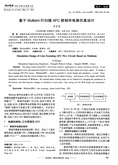
基于Multisim行扫描AFC锁相环电路仿真设计
Ke y wo r d s Mu l t i s i m2 0 01; l i n e s c a n n i n g; p h a s e - l o c k e d l o o p; AF C
M u h i s i m 软件 由加拿 大 I I T公 司开 发 , 可 适用 于 各 类 模 拟或 数字 电路 的设 计 工 作 , 并 具 有 丰 富 的仿 真 分 析能力_ l - 2 ] 。锁 相 环 电 路 广 泛 应 用 , 包 括于通 讯、 雷
d o i :1 0 . 1 6 1 8 0 / j . c n k i . i s s n l 0 0 7— 7 8 2 0 . 2 0 1 5 . 0 5 . 0 3 0
基 于 Mu l t i s i m 行 扫 描 AF C锁 相 环 电路 仿 真 设 计
李 宏 恩
( 长 治 医学 院 生 物 医 学 工 程 系 ,山 西 长 治 0 4 6 0 0 0 )
电路 的设计 。仿 真结果表 明,所设计 电路 实现 了对相位 的锁定 功能 ,同时依 托 m u h i s i m 灵 活简便的仿 真环境 ,还可通 过改 变元件参 数 ,并结合 观 察各 点 波形 的 变化 ,而找 到 电路 的 最佳锁 相 范 围数据 ,为 P C B设计 与 制作 节省 了设 计
afcmultisim软件由加拿大iit公司开发可适用于各类模拟或数字电路的设计工作并具有丰富的仿真分析能力1飞锁相环电路广泛应用包括于通讯雷达电视虹外计算机等众多领域所以电路能否实现图1锁相坏结构锁相功能对于设备正常工作影响较大
鼋a 叶拭 2 0 1 5 年 第2 8 卷 第 5 期
El e c t r o n i c S e i . & T e c h . / Ma y .e s c a n n i n g AF C PL L c i r c u i t , Mu l t i s i m2 0 01, wh i c h i s p o we r f u l i n c i r c u i t d e s i g n a n d s i mu l a t i o n, i s u s e d. S i mu - l a t i o n r e s u l t s s h o w t h a t t h e c i r c u i t d e s i ne g d h s a t h e f u n c t i o n o f p h a s e l o c k i n g . An d b e c a u s e o f t h e s i mp l e nd a f l e x i b l e s i mu l a t i o n e n v i r o n me n t o f Mu hi s i m ,t h e o p t i ma l p h a s e l o c k i n g r a n g e c a n b e o b t a i n e d b y c h a n g i n g t h e p a r a me t e r s o f
锁相环Simulink仿真模型
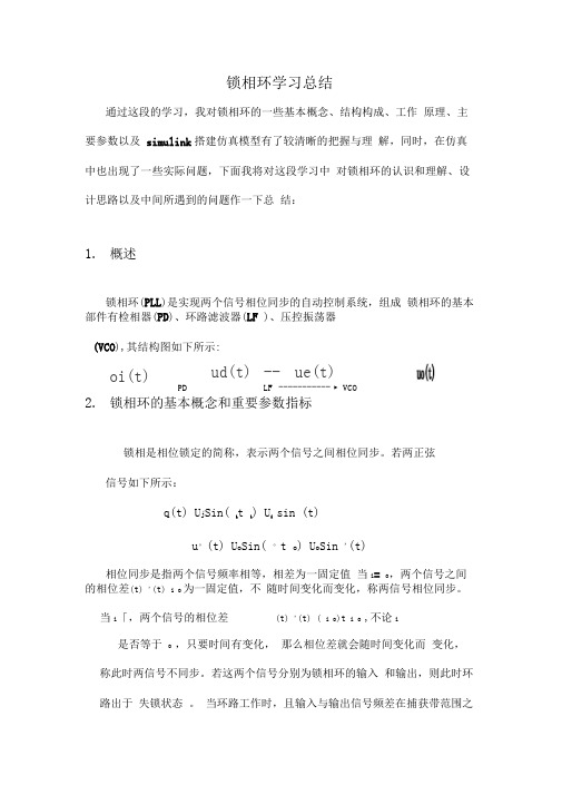
锁相环学习总结通过这段的学习,我对锁相环的一些基本概念、结构构成、工作 原理、主要参数以及 simulink 搭建仿真模型有了较清晰的把握与理 解,同时,在仿真中也出现了一些实际问题,下面我将对这段学习中 对锁相环的认识和理解、设计思路以及中间所遇到的问题作一下总 结:1. 概述锁相环(PLL )是实现两个信号相位同步的自动控制系统,组成 锁相环的基本部件有检相器(PD )、环路滤波器(LF )、压控振荡器 (VCO ),其结构图如下所示:2. 锁相环的基本概念和重要参数指标锁相是相位锁定的简称,表示两个信号之间相位同步。
若两正弦 信号如下所示:q(t) U j Sin( it i) U isin (t)u °(t) U o Sin( °t o ) U o Sin '(t)相位同步是指两个信号频率相等,相差为一固定值 当i = o ,两个信号之间的相位差(t) '(t) i o 为一固定值,不 随时间变化而变化,称两信号相位同步。
当i 「,两个信号的相位差(t) '(t) ( i o )t i o ,不论i是否等于 o ,只要时间有变化, 那么相位差就会随时间变化而 变化,称此时两信号不同步。
若这两个信号分别为锁相环的输入 和输出,则此时环路出于 失锁状态 。
当环路工作时,且输入与输出信号频差在捕获带范围之oi(t)ud(t) -- ue(t)PDLF ----------- ► VCO内,通过环路的反馈控制,输出信号的瞬时角频率v(t)便由。
向i方向变化,总会有一个时刻使得i= o,相位差等于0或一个非常小的常数,那么此时称为相位锁定,环路处于锁定状态。
若达到锁定状态后,输入信号频率变化,通过环路控制,输出信号也继续变化并向输入信号频率靠近,相位差保持在一个固定的常数之内,则称环路此时为跟踪状态。
锁定状态可以认为是静态的相位同步,而跟踪状态则为动态的相位同步。
毕业设计(论文)-锁相环电路仿真模型的研究论文

摘要:锁相环(简称PLL)是一种反馈控制系统,也是闭环跟踪系统,其输出信号的频率跟踪输入信号的频率。
本课题主要研究的是有关锁相环电路仿真模型的研究方法,深入探讨了锁相环的组成和工作原理及在各种电路中的应用,通过研究仿真模型及对锁相环的特性的分析,使我进一步掌握了锁相环的原理及在实际工作中的应用。
对锁相环仿真,使用MATLAB来实现是方便快捷的。
本课题介绍了锁相环电路的分类、工作原理、应用现状;建立了仿真锁相环电路捕捉过程的MATLAB模型,并进行了仿真,比较了不同种类锁相环电路的捕捉时间;对锁相环电路各种性能指标如同步带、捕捉带进行了分析,比较了两种锁相环电路的性能;最后提出了锁相环电路的改进方法,并对改进后的环路进行了仿真分析。
关键词:锁相环;鉴相器;滤波器;振荡器;MATLAB仿真Research of phase-locked loop circuit simulation model AbstractThe phase-locked loop (i.e. PLL) is one kind of feedback control system, is also the closed loop tracking system, its output signal frequency track input signal frequency. What this topic main research is the related phase-locked loop circuit simulation model research technique, discussed the phase-locked loop each aspect and the phase-locked loop the composition and the principle of work in depth, By studying the simulation model and analysis of the characteristics of the PLL,I further understand that the principle of phase-locked loop and the application in practical work. For phase-locked loop simulation's realization, use MATLAB to realize is the convenience quickly. Analyzed various performance indicators such as timing belt and capturing belt of the PLL circuit, comparing the performance of two phase-locked loop circuit and proposed the improvement of phase-locked loop circuit, and simulation to the Improved loop circuit.Key words: PLL; phase; filters; oscillators; MATLAB simulation目录1引言............................................ 错误!未定义书签。
锁相环仿真(基于MATLAB)
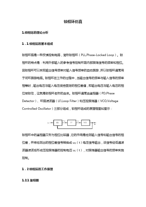
锁相环仿真1.锁相环的理论分析1.1锁相环的基本组成锁相环路是一种反馈控制电路,简称锁相环(PLL,Phase-Locked Loop)。
锁相环的特点是:利用外部输入的参考信号控制环路内部振荡信号的频率和相位。
因锁相环可以实现输出信号频率对输入信号频率的自动跟踪,所以锁相环通常用于闭环跟踪电路。
锁相环在工作的过程中,当输出信号的频率与输入信号的频率相等时,输出电压与输入电压保持固定的相位差值,即输出电压与输入电压的相位被锁住,这就是锁相环名称的由来。
锁相环通常由鉴相器(PD,Phase Detector)、环路滤波器(LF,Loop Filter)和压控振荡器(VCO,Voltage Controlled Oscillator)三部分组成,锁相环组成的原理框图如图示:锁相环中的鉴相器又称为相位比较器,它的作用是检测输入信号和输出信号的相位差,并将检测出的相位差信号转换成u D(t)电压信号输出,该信号经低通滤波器滤波后形成压控振荡器的控制电压u C(t),对振荡器输出信号的频率实施控制。
1.2锁相环的工作原理1.2.1鉴相器锁相环中的鉴相器(PD)通常由模拟乘法器组成,利用模拟乘法器组成的鉴相器电路如图示:鉴相器的工作原理是:设外界输入的信号电压和压控振荡器输出的信号电压分别为:式中的ω0为压控振荡器在输入控制电压为零或为直流电压时的振荡角频率,称为电路的固有振荡角频率。
则模拟乘法器的输出电压u D为:1.2.2 低通滤波器低通滤波器(LF)的将上式中的和频分量滤掉,剩下的差频分量作为压控振荡器的输入控制电压u C(t)。
即u C(t)为:式中的ωi为输入信号的瞬时振荡角频率,θi(t)和θO(t)分别为输入信号和输出信号的瞬时位相,根据相量的关系可得瞬时频率和瞬时位相的关系为:即则,瞬时相位差θd为对两边求微分,可得频差的关系式为上式等于零,说明锁相环进入相位锁定的状态,此时输出和输入信号的频率和相位保持恒定不变的状态,u c(t)为恒定值。
基于MATLAB的数字锁相环的仿真设计讲解
本科生毕业设计(申请学士学位)论文题目基于Matlab的数字锁相环的仿真设计作者姓名专业名称电子信息工程指导教师2014年5月学生:(签字)学号:答辩日期:2014 年 5 月24 日指导教师:(签字)目录摘要 (1)Abstract (1)1 绪论 (2)1.1 本文研究背景 (2)1.2 本文研究意义 (2)1.3 锁相环和仿真方式 (2)1.3.1 锁相环 (2)1.3.2 仿真方式 (2)1.4 本文研究内容 (3)2 模拟锁相环Matlab仿真 (3)2.1 模拟锁相环方案 (3)2.1.1 模拟鉴相器 (3)2.1.2 模拟低通滤波器 (6)2.1.3 模拟压控振荡器 (7)2.2 模拟锁相环仿真 (8)2.3 本章小结 (9)3 数字锁相环Matlab仿真 (10)3.1 数字锁相环方案 (10)3.1.1 数字鉴相器 (10)3.1.2 数字滤波器 (12)3.1.3 数字压控振荡器 (13)3.2 数字锁相环仿真 (14)3.3 本章小结 (15)4 总结与展望 (15)参考文献 (16)致谢 (18)基于Matlab的数字锁相环的仿真设计摘要:锁相环是一种能够自动跟踪信号相位并达到锁频目的的闭环负反馈系统。
数字锁相环在无线电领域得到较广泛的应用和发展。
而且已经成为雷达、通信、导航等各类电子信号产品不可替代的元器件之一。
锁相环的窄带跟踪性能使其得到较广泛应用。
因为锁相技术在实际应用中较为复杂,所以锁相环的设计通常采用仿真设计这种方式。
本次设计采用Matlab这一软件进行辅助仿真设计,完全能达到设计预期的目标。
Matlab中的Simulink仿真软件,具有很强的灵活性和直观性。
本次设计所采用的方法是在simulink中搭建模拟锁相的模型,并对模拟锁相环的组成、结构、设计进行不断的分析和改进。
然后根据模拟锁相环的原理进行改进,并搭建数字锁相环。
关键词:锁相环;自动跟踪;matlab;simulinkSimulative design of digital phase-locked loop based on MatlabAbstract:PLL is the automatic tracking system of close loop atracking signal phase. It is widely used in various fields of radio. It has become an irreplaceable part of radar, communication, navigation and all kinds of electronicsignal device. PLL is able to be widely used. Because, it has unique narrow-band tracking performance. However, because of the complexity of phase lock technique, for the design of PLL have brought great difficulty. This design uses Matlab, the simulative software for design assistance, can completely meet the design expectations. Simulink simulative software on Matlab, has strong flexibility and intuitive. Methods used by this project is to build the analog phase locked in the Simulink model, and the composition, structure, design of analog phase-locked loop of continuous improvement and analysis. It improved according to the principle of analog PLL, build digital phase-locked loop in Simulink, and then reach the simulation design of digitalphase-locked loop based on Matlab the design objective .Key words: PLL, Automatic tracking, Matlab, simulink1 绪论1.1 本文研究背景19世纪30年代法国H.de Bellescize首次提出同步检波这一概念,并且设计出锁相环电路这一划时代的研究成果 [1]。
通信工程专业-基于VisSim的锁相环性能仿真

基于VisSim的锁相环性能仿真摘要锁相环技术(PLL)是一门能够时相位不需要外界条件而自行控制刚兴起的技术。
锁相也叫相位锁定,我们也可称之为自动相位控制(APC),能使相位自行调整,能让两个信号相位同步。
上面的功能锁相环都能实现,同时其为进行负反馈的控制性系统。
由于锁相环具有捕获,跟踪和窄带滤波的作用;因此,被应用在通信、微处理器、以及卫星等许多领域。
在通信电路里,锁相环是一个重要部分,广泛应用于时钟系统设计中,包括相位同步等的。
本论文首先介绍锁相环历史发展和现在的研究进度,接着论文首先介绍了模拟锁相环,因为它是我们要进行后续研究的基石,于是它的工作原理就显得非常重要。
同时简单介绍了鉴相器、压控振荡器、环路滤波器工作原理等。
着重分析了锁相环的跟踪特性、捕获特性等各种特性。
我们进行了锁相环的数学模型的分析并且推导了环路方程,得到了需要的结论。
在分析和设计的过程中,同时本论文中主要通过对VisSi m/comm软件的学习和使用,利用其丰富的模板以及本科对锁相环原理知识的掌握对电路进行仿真。
后将学习总结出的相应理论与VisSim/comm中丰富的模块相结合实现仿真系统的建模,并且调整参数观察仿真波形输出,观察效果,最终对设计结论进行总结。
因VisSim/comm主要实现的就实通信系统的仿真,我们用其来实现锁相环性能的仿真,因此本论文主要介绍了用VisSim/comm来实现输入为复信号的锁相环的线性跟踪。
和调频信号的解调,BPSK的载波同步的仿真实现等等。
关键词:锁相环技术;VisSim软件;仿真;跟踪AbstractThe technology of phase locked loop (PLL) is a new technology for automatic phase contr ol. Phase locked is locking phase, we can also call it automatic phase control (APC), and the phase synchronization of two signals can be obtained by the method of phase automatic adju stment .The phase lock loop is the phase negative feedback control system for the task. Beca use of the capture, tracking and narrow band filtering, the phase lock loop is applied in many fields such as communication, microprocessor and satellite and so on. In the communication circuit, the PLL is an important part of the clock system designing, including the phase sync hronization and so on.Firstly this paper introduces the history of the PLL and the progress of the research. Then, the basic principle of PLL is introduced based on the structure of the traditional analog PLL. At the same time, the working principle of the phase detector, the voltage controlled oscillat or and the loop filter are simply introduced. The performance of the phase locked loop and th e performance of the PLL are analyzed. We analyze the mathematical model of the phase loc ked loop and deduce the loop equation, and get the conclusions. In the process of analysis an d design. At the same time in this paper mainly through the learning and use of software Vis Sim/comm,. To make the circuit simulation ,we use the PLL principle knowledge we learn w hen we are masters and make use of the rich templates and undergraduate. And then combini ng the theory summed up we learnt with the abundance modules of VisSim/comm to realize t he simulation system modeling, and adjust the parameters of the simulation waveform output observation, observation effect, the final conclusion of the design were summarized in this p aper. Because of VisSim/comm is mainly to achieve the real communication system simulati on, we used to realize the simulation of phase-locked loop performance, so this paper mainly introduces the VisSim/comm to realize input for a complex signal of the PLL linear tracking, input for income of complex signal and real signal tracking performance in comparison. An d demodulation of FM signal and BPSK carrier synchronization simulation and so on.Keywords: Phase Locked Loop technology;VisSim/comm software; simulation; tracke d目录第1章绪论 (1)1.1锁相环的历史发展 (1)1.2国内外研究现状 (2)1.3综述与分析 (3)第2章锁相环的介绍 (5)2.1锁相环的基本构成及琐相的概念 (5)2.2锁相环的数学模型 (6)2.3锁相环的特性 (11)2.3.1锁相环路的线性跟踪性能 (11)2.3.1.1 环路对典型输入相位的跟踪性能 (11)2.3.2锁相环路的稳定性 (14)2.3.3锁相环路的捕获特性 (15)2.4锁相环的应用 (16)2.4.1在调制与解调技术中的应用 (16)2.4.2在载波提取、跟踪与位同步技术中的应用 (16)2.4.3在测速与测距技术中的应用 (16)2.5本章小结 (17)第3章VisSim/Comm仿真 (17)3.1 VisSim/Comm的基本介绍 (17)3.2 VisSim/Comm的功能介绍 (18)3.2.1 如何使用VisSim (18)3.2.2 comm模块集 (19)3.3 本章小结 (28)第4章用VisSim/Comm对锁相环的仿真 (28)4.1对锁相环的性能的仿真 (28)4.2 锁相环应用的仿真 (31)4.2.1锁相环的鉴频 (31)4.2.2锁相环的BPSK载波跟踪 (35)4.3 本章小结 (37)结论 (37)参考文献基于visSim的锁相环性能仿真第1章绪论1.1 锁相环的历史发展自动相位制和控自动率频控制的融合叫做锁相环(PLL-Phase Locked L00P)。
锁相环的时域跟踪性能及MATLAB仿真分析
如图1 所示, (- s t0() 假设 t i + ), ) n U(- ono + 0) 0)U ( t0() t sc i o 。
为输入信号的振幅 , 3 为输入信号 的载波角 0f 频率 ; 为输 出信号的振幅 ,1 为输 出信 号的载 波 (0 )
0 引言
锁相环在 日常生 活中具有重要的应用 ,当我们
航 、雷达 、航空航天 、卫星 电视 、遥控遥测 等诸 多 方面。锁相环之 所以有这么多的应用 ,源于它的跟 踪性能 。本文从 定量和定性两方面 ,阐述锁相环最
打开 电视机时 ,立刻会体会到 锁相 环所 带来的好处 , 基本 的时 域跟踪性 能。并用 MA L T AB进 行仿 真分
模拟 锁 相 环 由鉴相 器 (D 、环 路 滤 波 器 ( F 、 环 l P) L) 。 压 控振 荡器 ( c ) v o 3部分 所组 成 。为研 究 问题方 便 ,
PLL r c i r or a e a i e t a k ng pe f m nc nd tm —do a n m i s ul rng a l i A一‘ AB i fa i na ̄ " ofM  ̄ l in m t yssoI… 1I LA
W e ua p n Y a i i Zha ou he g i X n i g, o M nl, ng Zh s n
人们通过进行 电视频道转换 ,可收看到清 晰的画面 和悦耳动听的音乐。此外 ,锁相环也广泛应用于导 析 。从而得 出对 电子设计具有一 定实用价 值的结 论。
巴
锁 相环的时域相位 模型
11锁 相环 的 组成 .
环路 的开环传递函数为 :
H0 ) Kd s K s ( = Ko 、 F() F()
- 1、下载文档前请自行甄别文档内容的完整性,平台不提供额外的编辑、内容补充、找答案等附加服务。
- 2、"仅部分预览"的文档,不可在线预览部分如存在完整性等问题,可反馈申请退款(可完整预览的文档不适用该条件!)。
- 3、如文档侵犯您的权益,请联系客服反馈,我们会尽快为您处理(人工客服工作时间:9:00-18:30)。
基于VisSim的锁相环性能仿真摘要锁相环技术(PLL)是一门能够时相位不需要外界条件而自行控制刚兴起的技术。
锁相也叫相位锁定,我们也可称之为自动相位控制(APC),能使相位自行调整,能让两个信号相位同步。
上面的功能锁相环都能实现,同时其为进行负反馈的控制性系统。
由于锁相环具有捕获,跟踪和窄带滤波的作用;因此,被应用在通信、微处理器、以及卫星等许多领域。
在通信电路里,锁相环是一个重要部分,广泛应用于时钟系统设计中,包括相位同步等的。
本论文首先介绍锁相环历史发展和现在的研究进度,接着论文首先介绍了模拟锁相环,因为它是我们要进行后续研究的基石,于是它的工作原理就显得非常重要。
同时简单介绍了鉴相器、压控振荡器、环路滤波器工作原理等。
着重分析了锁相环的跟踪特性、捕获特性等各种特性。
我们进行了锁相环的数学模型的分析并且推导了环路方程,得到了需要的结论。
在分析和设计的过程中,同时本论文中主要通过对VisSi m/comm软件的学习和使用,利用其丰富的模板以及本科对锁相环原理知识的掌握对电路进行仿真。
后将学习总结出的相应理论与VisSim/comm中丰富的模块相结合实现仿真系统的建模,并且调整参数观察仿真波形输出,观察效果,最终对设计结论进行总结。
因VisSim/comm主要实现的就实通信系统的仿真,我们用其来实现锁相环性能的仿真,因此本论文主要介绍了用VisSim/comm来实现输入为复信号的锁相环的线性跟踪。
和调频信号的解调,BPSK的载波同步的仿真实现等等。
关键词:锁相环技术;VisSim软件;仿真;跟踪AbstractThe technology of phase locked loop (PLL) is a new technology for automatic phase contr ol. Phase locked is locking phase, we can also call it automatic phase control (APC), and the phase synchronization of two signals can be obtained by the method of phase automatic adju stment .The phase lock loop is the phase negative feedback control system for the task. Beca use of the capture, tracking and narrow band filtering, the phase lock loop is applied in many fields such as communication, microprocessor and satellite and so on. In the communication circuit, the PLL is an important part of the clock system designing, including the phase sync hronization and so on.Firstly this paper introduces the history of the PLL and the progress of the research. Then, the basic principle of PLL is introduced based on the structure of the traditional analog PLL. At the same time, the working principle of the phase detector, the voltage controlled oscillat or and the loop filter are simply introduced. The performance of the phase locked loop and th e performance of the PLL are analyzed. We analyze the mathematical model of the phase loc ked loop and deduce the loop equation, and get the conclusions. In the process of analysis an d design. At the same time in this paper mainly through the learning and use of software Vis Sim/comm,. To make the circuit simulation ,we use the PLL principle knowledge we learn w hen we are masters and make use of the rich templates and undergraduate. And then combini ng the theory summed up we learnt with the abundance modules of VisSim/comm to realize t he simulation system modeling, and adjust the parameters of the simulation waveform output observation, observation effect, the final conclusion of the design were summarized in this p aper. Because of VisSim/comm is mainly to achieve the real communication system simulati on, we used to realize the simulation of phase-locked loop performance, so this paper mainly introduces the VisSim/comm to realize input for a complex signal of the PLL linear tracking, input for income of complex signal and real signal tracking performance in comparison. An d demodulation of FM signal and BPSK carrier synchronization simulation and so on.Keywords: Phase Locked Loop technology;VisSim/comm software; simulation; tracke d目录第1章绪论 (1)1.1锁相环的历史发展 (1)1.2国内外研究现状 (2)1.3综述与分析 (3)第2章锁相环的介绍 (5)2.1锁相环的基本构成及琐相的概念 (5)2.2锁相环的数学模型 (6)2.3锁相环的特性 (11)2.3.1锁相环路的线性跟踪性能 (11)2.3.1.1 环路对典型输入相位的跟踪性能 (11)2.3.2锁相环路的稳定性 (14)2.3.3锁相环路的捕获特性 (15)2.4锁相环的应用 (16)2.4.1在调制与解调技术中的应用 (16)2.4.2在载波提取、跟踪与位同步技术中的应用 (16)2.4.3在测速与测距技术中的应用 (16)2.5本章小结 (17)第3章VisSim/Comm仿真 (17)3.1 VisSim/Comm的基本介绍 (17)3.2 VisSim/Comm的功能介绍 (18)3.2.1 如何使用VisSim (18)3.2.2 comm模块集 (19)3.3 本章小结 (28)第4章用VisSim/Comm对锁相环的仿真 (28)4.1对锁相环的性能的仿真 (28)4.2 锁相环应用的仿真 (31)4.2.1锁相环的鉴频 (31)4.2.2锁相环的BPSK载波跟踪 (35)4.3 本章小结 (37)结论 (37)参考文献基于visSim的锁相环性能仿真第1章绪论1.1 锁相环的历史发展自动相位制和控自动率频控制的融合叫做锁相环(PLL-Phase Locked L00P)。
一开始研究锁相环是在1930-1939年,在这期间线无技电术的期初;20世纪30年代开始了步同制控理论的研究,1932年法国工程师贝尔赛什(Bellescize)发表了锁相环路的数学描述和同步检波论,[1] 作为公开发表对锁相环路的数学描述的先驱。
该技术首先出现在同步接收里,给同步检波一个与输入信号载波同频的本地参考信号[1],同步检波工作在低信噪比情况下,同时不具有大号信检波致导真失的缺点,所以比较引起重视,但并未在大范围内进行应用,主要是因为组成电路复杂,费用也很高。
20世纪40年代,PLL技术次首成功地在黑白电视接收机进行应用,主要是它水平描扫与直垂扫票同步电路中,它的优点是减小描扫随机发触使画面抖动情况,这些情况都是由噪声干扰得到的,最后得到不抖动不模糊的荧光屏图像;随后,在彩色电视接收机中也用锁相环路来同步彩色副载波信号[2];锁相环技术在这个转折点之后吸引了大量关注并且发展得很快。
在1950-1959这十年间,因为空间技术的进步,杰费(Jaffe)和里希廷(Rechtin)研究出导弹信标的跟踪滤波器,[3]当然这是一锁相环路为基础的。
他们也首次发表了含有声噪应效的PLL线性论理析分文章,同时搞定PLL最佳设计化问题[3];因为空间技术在历史洪流中的不断前进人们也对PLL和它理论知识的讨论,这件事情对PLL有今天的成就起了很大推动作用。
1960-1969年间,维特比(Viterbi)研究了无噪声PLL的非线性论理题问,随之出版相干通信原理一书[2]。
一开始PLL的搭建使用分立元件,因为术技、本成方面的问题,因此当年是非常难得的,所以只用于航天、航空等事军和密精量测等领域。
1965年前后成集电路术技出现,半导体术技也在发展,第一块PLL芯片出现[4],锁相环才才真正走向大规模发展与应用以一种不高的费用多功能身份。
一开始PLL只是模拟的(APLL),它的块模皆为模拟电路[2],基本上是由四象限拟模法乘器来组成PLL里P D,LF为通低波滤器(阻电R容电C构成),VCO有很多中构造;在APLL在定稳工作中,每一个块模皆能看成是性线踪跟,因此可以称为线性锁相环LPLL(Linear Phase L ock Loop);APLL对正弦特性号信的相位踪跟极佳,其环路特性很大一部分取决于P D。