安装调试说明书-摆角
全自动端子压着机使用说明书
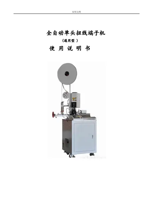
实用文档全自动单头扭线端子机(通用型 )使用说明书安全声明感谢您购买我们的产品全自动单头扭线端子机。
请您务必仔细阅读本说明书,并在完全理解其内容的基础上使用本设备。
为操作人员的安全着想,设备在设计阶段就充分考虑了安全方面的问题。
但是为了确保安全,下面所列的条款均为当进行安装、操作、检查、调整时,务必要遵守的事项,请加以注意:1. 接入电源必须进行可靠接地。
否则,万一发生因电气故障,可避免触电等对操作人员的伤害,将损失控制在最小限度。
2. 机箱罩是为了安全而安装的,所以在机箱罩没有可靠锁紧或移开的情况下不得开动设备。
因维修等原因需要取下机箱罩时,必须先断开电源、气源后,才能进行维修等作业。
3. 机械正在自动运转时,请勿将手等放到活动的部位或端子机模具之间。
有必要时,应先停止设备运转,断开电源、或拔下电源插头后才可进行。
不遵守以上原则而接触机械,有可能会引起意外的事故。
4. 由两个以上的人进行维修、保养时一定要一边互相招呼确认安全,一边进行操做。
5. 为了更换(电线、端子、端子机模具等)或清扫等,需要把手进入主机机体作业时,必须断开电源、气源后方可进行。
6. 发生了打掉端子的情况时,必须断开端子机的电源,用小镊子等工具作业。
绝对不能把手直接伸插入端子机内拿取。
7. 可编程控制器、传感器、驱动器等电气组件不要随意触动,否则可能会导致设备失去控制从而引起事故。
如有其它要求,请按本说明书封面所示联系方式与我们尽快取得联系。
概要介绍我司是国内专业从事电线末端加工设备的研发、生产、销售于一体的高科技企业。
本机吸收和借鉴了德国同行在电线末端加工设备方面的前沿技术,采用进口可编程控制系统及高精密步进电机、模块化的软件设计,保证了各个工作模块的有机联接,集进线、裁线、剥皮、端子压着、扭线(可选件)为一体,整套工序一次完成。
特点说明:4500PCS/H。
采用静音电子离合端子机.5.7英寸触摸屏,更加直观.数字化,图形化控制介面.送线机构改善,超低噪音.减少电磁阀的使用采用目前最先进的欧式端子机,机体结构精巧,市场上通用的OTP/2000 型等横、直送料模具均可适用,不改变现有的端子机操作方式,方便易用。
Festo DFPD 摆动驱动器操作手册说明书
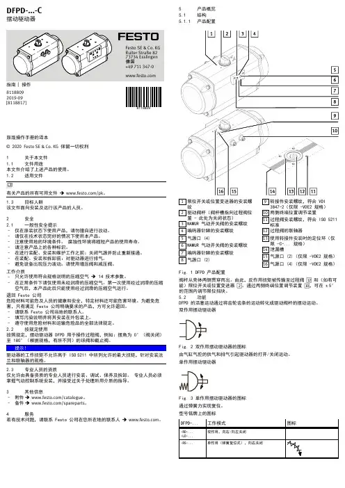
原版操作手册的译本© 2020 Festo SE & Co. KG 保留一切权利1关于本文件1.1文件用途本文件介绍了上述产品的使用。
1.2适用文件有关产品的所有可用文件 è /pk。
1.3目标人群该文件面向安装及运行该产品的人员。
2安全2.1一般性安全提示–仅在原装状态下使用产品,请勿擅自进行改动。
–请仅在技术状态完好的情况下使用本产品。
–注意使用地的环境条件。
腐蚀性环境将缩短产品的使用寿命。
–请注意产品上的各种标识。
–在进行装配、安装和维护工作之前:关闭气源并防止重新接通。
–在装配、安装和拆卸前:对驱动器进行排气。
–避免设备出现压力波动。
请使用增压阀和减压阀。
工作介质–只允许使用符合规格说明的压缩空气 è 14 技术参数。
–在正常条件下请仅使用未经润滑的压缩空气。
第一次使用经过润滑的压缩空气后,本产品此后只能使用经过润滑的压缩空气运行。
退回 Festo 公司危险材料可能危及人员的健康和安全,特定材料还可能危害环境。
为避免危害,只有满足 Festo 公司明确要求的产品,方可允许退回。
–请联系 Festo 公司当地的联系人。
–填写污染说明并将其安装在外包装上。
–遵守使用危险材料和运输危险品的全部法律规定。
2.2按规定使用按照规定,摆动驱动器 DFPD 用于操作过程阀,例如:摆角为 0°(阀关闭)至 180°(根据规格,有所不同)的球阀和截止阀。
驱动器的工作扭矩不允许高于 ISO 5211 中所列允许的最大扭矩,针对安装法兰和联轴器的规格。
2.3专业人员的资质仅允许由具备资质的专业人员进行安装、调试、保养及拆卸。
专业人员必须掌握气动控制系统安装,并接受过关于处理所用介质的指导。
3其他信息–附件 è /catalogue 。
–备件 è /spareparts 。
4服务若有技术问题,请联系 Festo 公司在您所在地的联系人 è 。
游乐设施结构原理及安装调试
游乐设施结构原理及安装调试第一节常见游乐设施结构及运动形式游乐设施品种繁多,其结构及运动形式各不相同,本节介绍几种常见的具有代表性的游乐设施的结构及运动形式。
一、自控飞机游艺机该游艺机(见图5-2-1 )由回转和升降两种运动形式。
回转运动大都为机械传动(个别也有用液力传动的),传动装置安装在地基上,飞机4 个升降几乎都采用液力传动,用支撑油缸3推动回转臂2,使飞机4上升或下降。
其升降大都由乘客自己操作,故起名为“自控飞机”。
必须具备的安全装置及措施:(1)座舱中设安全带和把手。
(2)回转臂升降限位装置。
(3)飞机平衡拉杆的保险装置。
(4)液压系统过压保护装置。
(5)停电及故障状态下疏导乘客措施。
二、观览车游艺机如图5-2-2 所示。
转盘结构分为桁架式和轮辐式。
传动方式分为中心轴传动、销齿传动及周边摩擦传动,一般中小型观览车采用前两种传动方式,而后一种传动方式主要用于大型观览车。
吊厢分为封闭式和半封闭式两种,目前,大多数观览车都采用封闭式吊厢。
这种类型的观览车,绕水平轴转动,速度都比较慢,一般为15-18m/min,以便在不停机的情况下,乘客能比较方便的上下。
其传动方式有机械传动和液力传动两种。
为了解决在停电情况下疏散乘客的问题,大中型观览车,一般都备有发电机或内燃机2 S悔證眦1峙托勒曾」r芝朴,i豹PH I忤閒戕買,’申療罡I6 ■ 3 沖會' »用旌轴J H廉押|九迅必须具备的安全措施:(1)吊厢门有两道锁(2)吊厢门、窗有防护栏杆。
(3)吊厢吊挂轴有保险措施。
(4)转盘能正反转。
(5)液压系统有过压保护装置。
(6)停电或故障状态下疏导乘客措施。
三、海盗船游艺机海盗船(见图5-2-3 )的运动方式为往复摆动,摆角一般为40-o60o 之间,速度为400m/min 左右。
传动方式均为摩擦传动。
在船体3 的下部有摩擦轨道9,摩擦轮5 紧紧地压在轨道9 上,靠磨擦轮的正反回转,实现船体 3 的往复摆动。
磨具安装与调试方案
磨具安装与调试方案磨具是加工厂中常用的工具之一。
磨具有着广泛的应用,比如在加工零件时用于磨削表面以获得更高的精度和光滑度。
然而,磨具的正确安装和调试对于保证其正常运转和有效使用至关重要。
在本文中,我们将介绍磨具安装和调试方案。
磨具安装在安装磨具时,我们需要遵循以下步骤:步骤1:准备工作在安装磨具之前,我们需要准备必要的工具和材料。
例如,我们需要有正确的规格和尺寸的螺母、垫圈、扳手、量规、磨具、喷油器等等。
步骤2:磨具位置选择好磨具的安装位置。
我们应该确保磨具站立平稳,不会因为震动而移动或倾斜,这对磨具的使用效果和寿命都有很大的影响。
步骤3:磨具安装安装磨具时,应确保磨具安装角度正确,与之相对应的机器床等部件的表面与磨具接触处应完全平整。
在安装磨具时应严格按照磨具安装说明进行操作。
同时,应注意螺母等紧固件的紧固力度,以确保磨具与机器床等零部件紧密连接。
步骤4:添加润滑安装磨具后,我们需要添加润滑剂。
在添加润滑剂时,应注意所使用的润滑剂的数量及其分配方式,以确保润滑达到预期效果。
磨具调试磨具调试,是一种人为创造一定的磨削条件,以调试磨削参数或磨削工艺的方法。
下面介绍磨具调试步骤:步骤1:空磨调试我们应该首先进行空磨调试。
在这一步骤中,不能使用工件进行磨削,而是将刀具移至工件加工点以进行磨削动作,以确定磨具的刀具间隙是否适当,并调整磨具参数。
步骤2:工件磨削实验在完成空磨调试之后,我们需要进行工件磨削实验。
在实验中,应根据所选工件材料、刀具材料、磨具类型、磨削参数等参数进行实验,并记录必要的参数。
步骤3:处理调试数据在工件磨削实验完成后,我们需要处理磨削参数的数据。
如果有必要,我们可以进行多组参数的调整和实验,以取得更为准确的数据。
结论磨具是加工厂中常用的工具,它具有广泛的应用。
然而,正确的磨具安装和调试对于保证其正常运转和有效使用至关重要。
在本文中,我们介绍了磨具安装和调试的方案和步骤,希望这些内容对您的工作有所帮助。
设备安装调试方案
设备安装调试方案一、项目背景在新建工厂或者现有工厂中,设备的安装和调试是保证生产线正常运行的必要步骤。
本方案旨在提供一个详细的设备安装和调试方案,确保设备能够安全、高效地投入使用。
二、设备安装准备工作1. 设备基础:根据设备的要求,确保安装基础的坚固稳定,以便于设备的固定和稳定运行。
2. 设备清洁:在安装设备之前,需要对设备进行清洁,确保设备表面没有灰尘、油脂等杂质,以维护设备的正常运行。
3. 安装材料准备:准备好所需的安装材料,包括螺丝、螺母、密封胶等,以便于设备安装过程中的需要。
4. 安全准备:在设备安装前,需要确保所在区域安全无隐患,并配备必要的安全设备,如安全帽、安全鞋等。
三、设备安装步骤1. 设备位置确认:根据工艺流程和生产要求,确认设备的安装位置,并进行标记,以便于正确安装设备。
2. 设备固定:根据设备的要求,使用适当的螺丝和螺母将设备固定在安装基础上,确保设备的稳定性和安全性。
3. 配管连接:根据设备的管道连接要求,进行相应的配管工作,确保设备能够顺利进行液体或气体的传输。
4. 电气连接:根据设备的电气连接图纸和要求,进行电气连接工作,确保设备能够正常运行。
5. 检查确认:在设备安装完成后,进行一次全面的检查,确保设备没有松动、漏水、漏电等问题,并进行必要的调整和修正。
四、设备调试步骤1. 设备预运行:在正式投入使用之前,需要进行设备的预运行检查,包括各个部件和功能的检验,以确保设备能够顺利启动。
2. 功能测试:根据设备的功能要求,进行相应的功能测试,以验证设备是否正常工作。
3. 参数调整:根据设备的工艺要求和生产需求,对设备的参数进行调整,确保设备能够达到预期的生产效果。
4. 故障排除:在设备调试过程中,如遇到故障或异常情况,需要及时排除故障,确保设备的正常运行。
5. 运行试生产:在设备调试完成后,进行一段时间的试生产,以验证设备的稳定性和可靠性,确保设备能够满足生产需求。
五、安全措施1. 安全培训:在设备安装和调试过程中,对参与工作的人员进行必要的安全培训,使其了解设备的安全操作规程和措施。
851-560 Rev. A 可调整立体摆位安装、维护与配件手册说明书
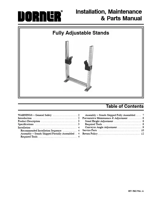
851-560 Rev. AInstallation, Maintenance& Parts Manual560−001.tifTable of ContentsWARNINGS − General Safety 2. . . . . . . . . . . . . . . . . . . . . . Introduction 2. . . . . . . . . . . . . . . . . . . . . . . . . . . . . . . . Product Description 3. . . . . . . . . . . . . . . . . . . . . . . . . . Specifications 3. . . . . . . . . . . . . . . . . . . . . . . . . . . . . . . . . . . . . . Installation 4. . . . . . . . . . . . . . . . . . . . . . . . . . . . . . . . . Recommended Installation Sequence 4. . . . . . . . . . Assembly − Stands Shipped Partially Assembled 4. Required Tools 4. . . . . . . . . . . . . . . . . . . . . . . . . . . . Assembly − Stands Shipped Fully Assembled 7. . . . Preventative Maintenance & Adjustment 8. . . . . . . . . . . . Stand Height Adjustment 8. . . . . . . . . . . . . . . . . . . . Required Tools 8. . . . . . . . . . . . . . . . . . . . . . . . . . . . Conveyor Angle Adjustment 9. . . . . . . . . . . . . . . . . . . . . . Service Parts 10. . . . . . . . . . . . . . . . . . . . . . . . . . . . . . Return Policy 12. . . . . . . . . . . . . . . . . . . . . . . . . . . . . . . . . . . . .IMPORTANT: Some illustrations may show guards removed. Do NOT operate equipment without guards. Upon receipt of shipment:D Compare shipment with packing slip. Contact factoryregarding discrepancies.D Inspect packages for shipping damage. Contact carrierregarding damage.D Accessories may be shipped loose. See accessory in-structions for installation.Dorner’s Limited Warranty applies.Dorner reserves the right to make changes at any time without notice or obligation.Warnings - General SafetyFully Adjsutable Stands Installation, Maintenance & Parts Manual851-560 Rev. A2Dorner Mfg. Corp.Fully Adjustable Stands Installation, Maintenance & Parts ManualDorner Mfg. Corp.3851-560 Rev. ARefer to Figure 1 for typical stand components.A Support Stand Pivot Bracket BLeg Support Bracket C Leg AssemblyD Crossmember*E Optional CastersF Angle Adjustment Point GHeight Adjustment Point* (Not used on 0719 or 1219 Height Models)Typical ComponentsFigure 1SpecificationsFixed and Adjustable Stand ModelsExample: 39MFA12−1267FAFully adjustable height, H style stand for a 12” (305mm) wide conveyor with a minimum height of 12” (305mm) and a maximum height of 67” (1702mm)with fixed foot pads. It comes fully as-sembled and has U.S. English docu-mentation.Product DescriptionRecommended Installation Sequence (see Table of Contents for page numbers)D Assemble stand(s), if requiredD Attach stand(s) to conveyorD Attach optional diagonal bracing (see DiagonalBrace Kit Manual)D Adjust stand height and angle (see Adjustment sec-tion, page 8)AssemblyStands Shipped Partially Assembled Required ToolsD5 mm Hex Key WrenchD6 mm Hex Key WrenchD17 mm Open−End Wrench (stands with casters, only)1.Typical components (Figure 2).Typical ComponentsH Leg Support Bracket (2x)IHardware Pack, Crossmember(quantity as required)J Hardware Pack, Fully Adjustable StandK Pivot Bracket (2x)L Crossmember (no crossmember on 7”−19”(178mm−483mm) high stand with feet or12”−19” (305−483mm) high stand with casters)M Plastic Tree Rivet (4x)N Tube End Cover (2x)O Stand Leg/Foot Assembly (2x) (used on stands with feet)orStand Leg Assembly (2x) (used on stands withcasters)PCaster Kit (2x) (used on stands with casters)Figure 2NOTE: 7”−19” (178mm−483mm) high stands with feet and 12”−19” (305−483mm) high stands with casters do not use a crossmember. For assembly of these stands, continue with step 7.2.Open crossmember hardware pack (I of Figure 2).InstallationFully Adjsutable Stands Installation, Maintenance & Parts Manual851-560 Rev. A4Dorner Mfg. Corp.Fully Adjustable Stands Installation, Maintenance & Parts ManualDorner Mfg. Corp.5851-560 Rev. A3.Install four button head screws (R of Figure 3) andhex nuts (Q) on crossmember (L). Do not tighten screws.Figure 3L4.Align hex nuts (Q of Figure 4) on crossmember (L)to t −slots (S) at top of stand leg (O). Slide crossmem-ber to bottom of stand leg. Do not tighten screws.Figure 4OLQS5.Repeat step 4 for opposite stand leg.6.Tighten four button head screws (R of Figure 5) to150 in−lb (17 N −m).Figure 5NOTE: Steps 7 and 8 apply to stands with castersonly. For stands with feet, go to step 9.T Caster V Lock Nut(Discard enclosed carriage bolt)Caster Kit (P of Figure 2) Components7.Open caster kit (P of Figure 2). Install caster (T ofFigure 6) over bolt (U). Bolt is pre −assembled on stand leg (O). Secure caster with lock nut (V).Figure 6UO8.Tighten lock nut (V of Figure 7) to 30 ft −lb (40N −m).Figure 7InstallationFully Adjsutable Stands Installation, Maintenance & Parts Manual851-560 Rev. A6Dorner Mfg. Corp.NOTE: Pivot bracket (K) must be installed on side ofleg support (H) opposite of warning label (X). When installed, round end of pivot bracket will be down and warning label will be upright, as shown.Screws (W) for attaching pivot brackets (K) to sup-port legs (H) must be installed in opposite set of holes on opposite support leg to properly attach piv-ot brackets to conveyor.9.Open fully adjustable stand hardware pack (J ofFigure 2). Attach pivot bracket (K of Figure 8) to leg support (H) with two flange socket head screws (W).Do not tighten screws.Figure 810.Repeat step 9 for opposite pivot bracket (see note,above).11.Install two button head screws (Y of Figure 9) andhex nuts (Z) on leg support (H). Do not tighten screws.Figure 9YZ12.Repeat step 11 for opposite leg support.13.Align hex nuts (Z of Figure 10) on leg support (H)to t −slots at top, outside of stand leg (O). Slide legsupport down stand leg until conveyor mounting holes (AA) on pivot bracket (K) are approximately the same height as the lower t −slots on conveyor.Tighten button head screws (Y) just enough to keep leg support in position.Figure 10HKAA14.Repeat step 13 for opposite stand leg.15.Install one t −bar (AB of Figure 11) in bottom t −sloton each side of conveyor (AC).Figure 11ACT −Bar (AB) InstalledInstallationFully Adjustable Stands Installation, Maintenance & Parts ManualDorner Mfg. Corp.7851-560 Rev. ANOTE: Make sure conveyor section is properly sup-ported and at the proper height and angle before at-taching stand.16.Attach pivot bracket (K of Figure 12) to t −bar (ABof Figure 11) with two socket head screws (AD of Figure 12). Do not tighten screws.Figure 12ADKNMO17.Repeat step 16 for opposite stand leg.18.Tighten four socket head screws (AD of Figure 12)to 124 in −lb (14 N −m).19.Tighten four flange socket head screws (W of Figure8) to 24 ft −lb (33 N −m).20.Tighten four button head screws (Y of Figure 10) to17 ft −lb (22.5 N −m).21.For final height and angle adjustments see page 9.22.Attach tube end cover (N of Figure 12) on stand leg(O) with two plastic tree rivets (M).23.Repeat step 22 for opposite stand leg. Stands Shipped Fully Assembled1.No stand assembly is required.2.To attach stand to conveyor, see steps 15 through 18starting on page 6.3.For final height and angle adjustments see page 9.InstallationFully Adjsutable Stands Installation, Maintenance & Parts Manual851-560 Rev. A8Dorner Mfg. Corp.Stand Height AdjustmentRequired Tools1.Support conveyor section (AC of Figure 13).2.Loosen two flange socket head screws (W) on eachpivot bracket (K).3.Loosen two button head screws (Y) on each leg support (H).4.Slide both leg supports (H) up or down on stand legs (O) to the required height. If necessary, adjust heightof each leg support until conveyor is level from side to side.5.Tighten four button head screws (Y) to 17 ft −lb (22.5N−m).6.Tighten four flange socket head screws (W) to 24ft −lb (33 N −m).Figure 13HConveyor Angle AdjustmentRequired Tools D 6 mm Hex Key Wrench1.Loosen two flange socket head screws (W of Figure14) on both sides of stand .Preventive Maintenance and AdjustmentFully Adjustable Stands Installation, Maintenance & Parts ManualDorner Mfg. Corp.9851-560 Rev. AFigure 14W2.Adjust conveyor to desired angle.3.Secure flange socket screws (W of Figure 14) to 24ft-lb (18 Nm).4.If conveyor is equipped with diagonal bracing (AE ofFigure 15), socket head screw (AF) must be loosened to adjust conveyor angle. Secure screw to 100 in −lb (11N −m) after angle adjustment.Figure 15AEAFFully Adjsutable Stands Installation, Maintenance & Parts Manual851-560 Rev. A10Dorner Mfg. Corp.NOTE: For replacement parts other than those shown on this page, contact an authorized Dorner Service Center or the factory.Fully Adjustable Stand w/Feet or Casters10511101861537291341416oror171218192018Item Part Number Description1920883M Scr, Flange, Socket M8−1.25x16MM 2300150M Bar, Tee, Drop −In, 1.88 CD Metric 3920612M Scr, Sock, Metric M6−1.00x12MM 4300825M Bracket, Pivot, Stand Mounting 5710016Bracket, Leg Support6300324P Label, Warning, Overhead Hazard 7807−1289Rivet, Tree, 0.22 Dia. x 0.75 Long 8710003Cover, Tube End, Stand 9See Leg Table Leg, Stand10708180P Scr, Sock, Metric M6−1.00x25MM 11710004Foot, Stand, Floor Mtg12991001M Nut, Hex, Full M10−1.5013991001M Nut, Hex, Full M10−1.5014807−640Caster, 4”15710221Plate, Caster Mtg.16930625M Scr, Flat, Metric M6−1.0x25MM 17961030M Scr, Cap, HD −Hex M10−1.5x30MM 18911016M Scr, Bttn, Metric M10−1.50x16MM 19See Cross-member Table Crossmember*20710006Plate, End, Crossmember Stand* No crossmember used on 7”−19” (178mm −483mm) high stand with feet or 12”−19” (305mm −483mm) high stand with casters.Service PartsItem 9: Leg Table:With FootStand Height Range Leg Part Number 7”−19” (178mm−483mm)710211−01600 12”−31” (305mm−787mm)710211−02663 12”−43” (305mm−1092mm)710211−03863 12”−55” (305mm−1397mm)710211−05063 12”−67” (305mm−1702mm)710211−06263With CasterStand Height Range Leg Part Number 12”−19” (305mm−483mm)710211−01100 17”−31” (432mm−787mm)710211−02163 17”−43” (432mm−1092mm)710211−03363 17”−55” (432mm−1397mm)710211−04563 17”−67” (432mm−1702mm)710211−05763Item 19: Crossmember TableStand Width Crossmember Part Number 8” (203mm)710210−0142810” (254mm)710210−0162812” (304mm)710210−0182814” (357mm)710210−0202816” (406mm710210−0222818” (457mm)710210−0242820” (508mm)710210−0262822” (559mm)710210−0282824” (610mm)710210−0302826” (661mm)710210−0322828” (711mm)710210−0342830” (762mm)710210−0362832” (813mm)710210−0382834” (864mm)710210−0402836” (915mm)710210−0422838” (966mm)710210−0442840” (1016mm)710210−0462842” (1067mm)710210−0482844” (1118mm)710210−0502846” (1169mm)710210−0522848” (1220mm)710210−05428Service PartsFully Adjustable Stands Installation, Maintenance & Parts ManualDorner Mfg. Corp.11851-560 Rev. A851-560 Rev. APrinted in U.S.A.For replacement parts, contact an authorizedDorner Service Center or the factory.Return PolicyNo returns will be accepted without prior written factory authorization. When calling for authorization, please have the following information ready for the Dorner Factory representative or your local distributor: and address of customer.2.Item(s) being returned.3.Reason for return.4.Customer’s original order number used when ordering the item(s).5.Dorner or distributor invoice number.A representative will discuss action to be taken on the Returned items and provide a Returned Goods Authorization Number to reference.There will be a 15% restocking charge on all new items returned for credit where Dorner was not at fault. These will not be accepted after 60 days from original invoice date. The restocking charge covers inspection, cleaning,disassembly, and reissuing to inventory.If a replacement is needed prior to evaluation of returned item, a purchase order must be issued. Credit (if any) is issued only after return and evaluation is complete.Dorner has representatives throughout the world. Feel free to contact Dorner for the name of your local representative.Our technical sales and service staff will gladly help with your questions on Dorner products.For a copy of Dorner’s Limited Warranty, contact factory, distributor, service center or visit our website @。
CommScope 远程电子摆角系统文档说明书
Capacity SolutionsOptimize capacity with better antenna beam managementRemote Electrical Downtilt SystemsFor more information, visitWhat’s your position onperfection?2Remote electrical downtilt systemsfrom CommScopeCommScope’s highly precise, yet flexible, remoteelectrical tilt (RET) solutions enable you to optimize,control and maintain the perfect antenna beamposition from anywhere—without costly site visits,tower climbs or network downtime.• Respond quickly to changing traffic needs• Prevent pattern blooming, common withmechanical tilt• Reduce human error with computer-controlledaccuracy• Ideal for all sites, including isolated ordifficult-to-access sitesMore importantly, the ability to control and maintainprecise beam tilt leads to less intersector interferenceand noise and allows you to maximize the capacityand call quality of your LTE services.As a wireless network manager, you feel the constant pressure to increase the capacity and improve thequality of service in your network. Sure, LTE can be a powerful tool, but it is also limited by capacity-crippling noise and interference. So you take a hard look at your network antennas—a major source ofnoise and interference.As long as the antenna’s beam is precisely and accurately positioned, the amount of potentialinterference can be managed. But, if the alignment shifts or a change in the sector requires the beamto be repositioned, can you afford the cost and timeof repeated tower climbs? Is there a better way tokeep your antennas and network optimized?Absolutely.quality of service in youcrippling noise and intenoise and interference.As long as the antennainterference can be maFor more information, visit 3Don’t just respond to change—control itWhen it comes to your antenna beam position, there is no “set it and forget it.” The RF environment and demands are constantly in flux. Every site has a lifecycle: pre-installation to deployment to maturity. As traffic patterns change, your radiation patterns have to adapt. You need instant and complete control over the positioning of every array in every antenna—regardless of where it is. That’s the value of CommScope’s RET solutions.Basic design of CommScope’s RET system CommScope’s RET systems feature significant design flexibilitythat starts with the RET architecture within the antenna. But thebasic elements and their relationship to each other are consistent.In a typical RET system the controller sends tilt commands to themotorized antenna actuator. The actuator alters the electricaldowntilt by adjusting the phase shifter.Various RET system devices, includingthe antenna’s actuators,are connectedto the controller using control cables.Multiple actuators can bejoined together either bydaisy-chaining control cablesor by using junction boxes.The base station connects tothe RET system either througha single home run control cableor over the RF transmission lineequipped with smart bias teesthat inject the AISG signal intothe existing RF cable.interference in urban metro cells. ByRET technology into our newest multiband,multiport twin-beam antennas. Not only does this Pushing the boundaries of RET design to take you furtherFor more information, visit 4For more information, visit5ActuatorsActuators perform the actual electrical downtilt of the antenna beam. CommScope offers an extensive portfolio of antennas with integrated internal actuators for reduced wind load and increased aesthetic appeal. Or upgrade your existing RET compatible antennas with our external actuators that install easily in justminutes—no tools required. Many CommScope RET compatible antenna designs are also available with factory-fitted external actuators that include a protective shroud.Network multiple actuators by daisy-chaining control cables, to support up toInside CommScope’s RET portfolioCommScope’s RET portfolio provides all the product solutions, technical expertise and system support to maximize your antennas’ performance and your network’s value. All system components support AISG 1.1 and 2.0. And, because CommScope can provide a complete turnkey solution, you have one trusted partner for all your RET and antenna needs.Easily retrofit antennas withRET—no tools neededFor more information, visit6ControllersRET controllers are the brains of the system—andCommScope’s controllers are as smart, flexible and capable as they come. There are three different models for all the ways you need to work.The rack mount controller allows remote access from a central office and provides alarm monitoring and optional remote firmware update for actuators, AISG TMAs, and controllers.RET Master Portable Diagnostic Controller Rack Mount Controllerable trollerFor more information, visitThe only thing more relentless than the pressure is ourcommitment to help you deal with itUnfortunately, the pressure to increase your data capacity while reducing your total cost of ownership won’t let upanytime soon. Even as new and promising capacity-generating technologies like LTE emerge, noise and interference will always threaten the gains you’ve fought so hard to achieve. Success requires a new way of thinking—about interference management, about beam control, and about how to squeeze more performance from your wireless network.Fortunately, however, you’re not alone. With our technical expertise, worldwide presence and comprehensive portfolio of RET components and systems, CommScope is at your side. We can provide the solutions and guidance needed to put today’s most advanced RET technology to work, with pattern shaping, sector sculpting, metro cell integration, noise filtering and more—all from the company that started it all.7Smart Bias TeesCommScope’s AISG smart bias tees inject the power and control signals into an existing RF cable—eliminating the need for a long AISG cable run from the base to the top of the tower. Supporting 694–2690 MHz bands, they feature female-female, female-male, and male-female connector options for both top and bottom smart bias tees.Junction BoxesJunction boxes divide and direct data and power from the RET control unit to theactuators and/or additional junction boxes. With 4- and 7-way models available, you can connect up to 32 AISG antenna line devices to a single controller. Each junction box features one male input port and four or seven female output ports and easily mounts to a pole or a flat surface using the provided brackets. Select from a wide variety of configurations to reduce the number of RET control cables needed.Control CablesOur AISG control cables feed data and power from the controller to the RET components. Available in lengths from 0.50 meters to 100 meters, each cable is terminated with male and female connectors to meet your specified length. Right-angle AISG male connector options are available in a 0.50-meter length with 6- and 9-o’clock key positions.Lightning Protection Unit and Grounding Kits Able to withstand a lightning surge of 10 strikes at 600 Amps, 10/350 waveform and equipped with a grounding stud, CommScope’s lightning protection unit safeguards your RET controller and antenna line devices in the worst of storms. The lightning protection unit easily mounts to a pole or flat surface and is AISG and RoHS compliant. CommScope provides RET grounding kits for grounding control cables at connection without the need to cut and splice, as well as those used to ground RET components.LigAblandsafeTheandconuseCommScope (NASDAQ: COMM)helps companies around the worlddesign, build and manage their wiredand wireless networks. Our networkinfrastructure solutions help customersincrease bandwidth; maximize existingcapacity; improve network performanceand availability; increase energyefficiency; and simplify technologymigration. You will find our solutionsin the largest buildings, venues andoutdoor spaces; in data centers andbuildings of all shapes, sizes andcomplexity; at wireless cell sites and incable headends; and in airports, trains,and tunnels. Vital networks around theworld run on CommScope solutions.Visit our website or contact your local CommScope representative for more information.© 2016 CommScope, Inc. All rights reserved.All trademarks identified by ® or ™ are registered trademarks or trademarks, respectively, of CommScope, Inc. General Electric and the GE logo are registered trademarks of General Electric Company used with permission. For planning purposes only. CommScope reserves the right to modify the specifications or product without notice. This document is not intended to modify or supplement and specifications or warranties relating to CommScope products or services.CommScope is certified according to ISO 9001, TL 9000, and ISO 14001.BR-110027-EN (03/16)。
组角机的调试方法
组角机的调试方法组角机是一种专门用于加工和组装角度构件的设备,广泛应用于各种金属框架、门窗、家具等制造行业中。
为了确保组角机的正常运行和高效率,调试是一个至关重要的环节。
本文将详细介绍组角机的调试方法,以确保设备的准确性和稳定性。
一、调试前的准备工作在调试组角机之前,首先需要进行一些准备工作。
这包括:1.检查设备:仔细检查组角机的各个部件是否完好,紧固件是否松动,确保设备没有损坏或缺陷。
2.清理设备:清除设备表面的杂物和灰尘,确保设备干净整洁。
3.准备工具:准备好所需的调试工具,如扳手、螺丝刀、测量工具等。
二、调试步骤1.调整送料装置:首先调整送料装置,确保送料准确且稳定。
根据加工要求,调整送料速度和送料位置,确保送料与组角机的加工速度相匹配。
2.调整切割装置:切割装置是组角机的关键部分,需要确保切割准确。
调整切割装置的切割深度和切割角度,使其与所需的角度相匹配。
同时,检查切割刀具的锋利度,确保切割质量。
3.调整压角装置:压角装置用于将角度构件固定在组角机上。
调整压角装置的压力和位置,确保角度构件能够稳定地固定在设备上,并且不会对构件造成损坏。
4.调整定位装置:定位装置用于确定角度构件的位置。
根据加工要求,调整定位装置的位置和角度,确保构件能够准确地定位在组角机上。
5.调试自动控制系统:对于配备自动控制系统的组角机,需要进行自动控制的调试。
检查传感器和执行机构的工作状态,确保自动控制系统的准确性和稳定性。
同时,调整控制系统的参数,以适应不同的加工要求。
三、调试后的检查完成调试后,需要进行一些检查工作,以确保组角机的正常运行。
这包括:1.加工测试:进行一些试加工,检查组角机的加工精度和稳定性。
通过测量加工后的角度构件,验证组角机的准确性和重复性。
2.安全检查:检查组角机的安全装置是否有效,如急停按钮、防护罩等。
确保设备在运行过程中能够保证操作人员的安全。
3.清理现场:调试完成后,清理调试现场,将工具和调试设备归位。
摆式仪操作规程
摆式仪操作规程引言概述:摆式仪是一种常用的测量仪器,广泛应用于物理实验、工程测量等领域。
正确操作摆式仪是保证测量准确性的关键。
本文将详细介绍摆式仪的操作规程,包括仪器的准备工作、仪器的调试、测量的步骤以及注意事项。
一、仪器的准备工作:1.1 选择合适的摆式仪:根据测量对象的大小和质量,选择合适的摆式仪。
普通来说,较小的物体适合使用小型摆式仪,而较大的物体则需要使用大型摆式仪。
1.2 摆式仪的安装:将摆式仪固定在平稳的工作台上,确保其稳定性。
调整仪器的水平度,以保证测量的准确性。
1.3 摆式仪的校准:在使用摆式仪之前,需要进行校准。
校准的目的是确定仪器的零点和灵敏度,以确保测量结果的准确性。
二、仪器的调试:2.1 零点调试:将摆式仪的指针置于零刻度位置,调整仪器的调零螺丝,使指针彻底指向零刻度。
确保仪器的零点准确无误。
2.2 灵敏度调试:选择适当的摆动幅度,将摆式仪摆动一定角度,记录指针的偏转量。
根据偏转量计算出仪器的灵敏度,并进行调整,使其符合要求。
2.3 确认调试结果:重复进行零点和灵敏度调试,直至调试结果符合要求。
记录下最终的调试参数,以备后续测量使用。
三、测量的步骤:3.1 确定测量的目标:明确需要测量的物理量,并确定测量的方法和步骤。
3.2 准备测量装置:根据测量的需要,选择合适的附件和装置,如测量杆、重物等。
3.3 进行测量操作:按照事先确定的步骤,进行测量操作。
注意保持仪器的稳定性,避免外界干扰对测量结果的影响。
四、注意事项:4.1 避免震动和干扰:在测量过程中,要避免仪器受到震动和外界干扰,以免影响测量结果的准确性。
4.2 注意仪器的温度:摆式仪的测量结果会受到温度的影响,因此在测量前要确保仪器的温度稳定,并进行相应的修正。
4.3 定期检查和维护:定期检查摆式仪的各个部件是否正常,并进行必要的维护和保养,以确保仪器的正常使用和测量准确性。
五、总结:摆式仪是一种重要的测量仪器,正确操作摆式仪对于保证测量结果的准确性至关重要。
摆式磨粉机的安装调试与运行参数设置
摆式磨粉机的安装调试与运行参数设置一、引言摆式磨粉机是一种常用的粉磨设备,广泛应用于矿山、冶金、建材等行业。
为了确保摆式磨粉机能够正常运行并获得最佳的加工效果,安装调试和运行参数设置是非常关键的环节。
本文将详细介绍摆式磨粉机的安装调试步骤以及运行参数的设置方法。
二、摆式磨粉机的安装调试1. 安装前准备在进行摆式磨粉机的安装调试之前,需进行一系列的准备工作:(1)查看设备和配件的完整性,并确认是否符合设计要求;(2)清理设备,并确保周围环境干燥、洁净;(3)安装调试人员应熟悉相关设备的使用手册和技术参数,并具备相应的专业知识。
2. 安装摆式磨粉机摆式磨粉机的安装步骤如下:(1)根据设备布局图,确认机器的位置和安装方式;(2)使用起重设备将摆式磨粉机的主机和配件安装到指定位置,确保安装牢固;(3)安装电气控制柜,并进行必要的接线;(4)根据设备图纸和安装说明,安装传动装置;(5)设备安装完成后,进行整机的水平校正和轴线调整。
3. 调试摆式磨粉机在完成安装后,需要对摆式磨粉机进行调试,以确保其正常运行:(1)首先检查设备的润滑情况,确保各润滑点有足够的润滑油;(2)进行电气连接的测试,确保电气系统正常;(3)启动摆式磨粉机,并观察其运行情况,检查各传动部件是否正常工作;(4)开启磨粉机的进料装置,逐渐调整物料供给量,观察磨矿机的出料情况;(5)根据研磨粉末的质量要求,适时调整磨矿机的速度,并进行反复试验,直至满足要求。
三、摆式磨粉机的运行参数设置1. 速度调节摆式磨粉机的转速对磨石和磨矿机的研磨效果有着重要的影响。
过高的转速会导致磨损加剧,而过低的转速则影响研磨的效率。
因此,在进行摆式磨粉机的运行参数设置时,需要合理调节转速,以达到最佳效果。
2. 进料量控制合理控制摆式磨粉机的进料量可以保证磨矿机正常运行,并对研磨效果产生重要影响。
进料量需根据物料的性质和生产要求进行调整,避免过量或过少的进料导致矿石堵塞或加工效率低下。
- 1、下载文档前请自行甄别文档内容的完整性,平台不提供额外的编辑、内容补充、找答案等附加服务。
- 2、"仅部分预览"的文档,不可在线预览部分如存在完整性等问题,可反馈申请退款(可完整预览的文档不适用该条件!)。
- 3、如文档侵犯您的权益,请联系客服反馈,我们会尽快为您处理(人工客服工作时间:9:00-18:30)。
“#4锅炉改烧烟煤” 燃烧器摆动气动执行器安装调试说明书航天科工哈尔滨风华有限公司电站设备分公司注意:1.请在设备到达现场后,放置在干燥清洁的地方,防止受潮淋雨,造成设备进水导致设备不能正常工作并且影响设备寿命。
在设备安装前认真阅读本说明书,并严格按照说明书的要求执行。
2.气源压力一定不能超过0.7MPa。
3.在连接气路之前,对供气设备及气路进行检查,一定要用压缩空气吹扫连接气路用管路,以免灰尘、杂质堵塞气动元件。
4.要使用洁净的仪表气源,以免降低气动元件的使用寿命。
5.请在安装调试时特别注意以上几点要求,对于使用过程中,由于误操作引起的损失,我公司不承担任何经济损失。
一、概述本气动执行器控制系统是以压缩空气为动力能源,通过输入DC4~20mA模拟信号,输出与输入信号相对应的位移,推动被调节风门动作到相应开度位置。
本系列产品具有结构简单、定位精度高、自锁牢固、性能可靠、调试简便、安装维修方便等特点,可用于电力、化工、石油、冶金等行业,用以线性调节各种风门挡板和阀门的开度。
二、主要技术指标:2.1 环境温度: -25℃ ~ 120℃2.2 相对湿度: ≤ 90%2.3 输入工作气源压力: 0.4 ~ 0.7 MPa2.4 输入电信号:DC4~20mA2.5 输出反馈信号:DC4~20mA2.6 电源:AC220V 50Hz2.7气缸参数:上组燃烧器执行器 φ350x171中组燃烧器执行器 φ350x3302.8 基本误差:≤±1.5%2.9 回差:≤额定行程 1%2.10 具有“三断”保护功能(断气、断电、断信号)三、基本性能及特点燃烧器摆动气动执行器系统由气动执行机构和控制柜两部分组成。
气动执行机构部分主要由气缸、SIEMENS智能定位器反馈装置及安装结构件组成。
控制柜由SIEMENS智能定位器、电子开关、闭锁阀及电磁阀等组成。
此执行器采用进口SIEMENS电气阀门定位控制器,具有结构简单、调试方便、定位精度高、一经初始化确认就可实现自动调试,整个调试过程非常简便。
此定位控制器并具有三位一体功能,无须配置其它元器件,就可实现电信号与气压力信号转换、位置定位功能及位置信号反馈功能,可为控制室提供风门不同开度的反馈信号。
此执行机构具有三断自锁保护功能(断气、断电、断信号)。
四、系统组成湛江电力有限公司#4锅炉改烧烟煤燃烧器摆动气动执行器控制系统由12台气动执行机构(上组共计8台,中组共计4台)和同一规格的12面控制柜组成。
五、设备安装5.1 气动执行机构的安装:燃烧器摆动气动执行器的气动执行机构相同组的规格尺寸一致,外型尺寸和安装尺寸已经与东锅设计确认。
即气动执行机构与相应的燃烧器风门挡板安装接口应该一致,现场直接安装在相应的位置上即可。
注意上、中两组燃烧器与两种执行机构向对应,不得对应错误。
5.2 气动控制柜的安装:见图纸:燃烧器摆动气动执行机构控制柜外形图:《SCAZ/F201-0》;燃烧器摆动气动执行机构外形图:《SCAZ/F202-0》;燃烧器摆动气动执行机构外形图:《SCAZ/F102-0》。
燃烧器摆动气动执行机构控制系统线缆连接图《SCAZ200-0LL》。
5.3 气管路和电缆铺设5.3.1 气管路的铺设:燃烧器摆动气动执行机构和控制柜都安装就位后,根据执行机构和控制柜的位置和系统图铺设气动管路。
系统图要求工作气源进入到控制柜,气管路从控制柜再铺设到相应的执行机构。
5.3.2 设备接口:1)气动执行机构带有与金属软管匹配的接头;2)金属软管带有φ10-M16x1.5不锈钢双卡套接头;3)现场铺设的气管路为:φ10x2不锈钢管;4)气动控制柜本体带有φ10不锈钢穿板双卡套接头;5.3.3 气管路标准:现场铺设的气管路必须是输送流体用不锈钢无缝钢管,按其标准壁厚均匀,外表规则,表面无裂痕、小孔,在实验压力下,不得有渗漏。
5.3.4 铺设前用洁净的压缩空气吹扫,焊接时满焊,保证气管路不能有泄漏点。
5.3.5 气管路铺设原则:1)根据气动执行机构和气动控制柜的位置,依就近安装的原则,连接气动执行机构和气动控制柜。
2)控制柜安装在( )平台上,每一角放置三个气动控制柜。
3)定义各燃烧器的气动执行机构的标识及气动控制柜的气路标识,连接时要一一对应,不得接错。
4)现场连接的气管路铺设美观、整齐、规范,在1m长左右处加装固定架,防止管路震动。
5)管路之间的连接要密封,不得有漏气现象。
5.3.6 电缆铺设:根据各执行机构和控制柜的电缆接线图对电缆的要求和执行机构、控制柜及综控室的相对位置铺设电缆。
连接时要注意标识不得接错。
注意电源匹配和信号源匹配。
电缆铺设美观、整齐,就近原则,以免信号衰减。
六、设备调试设备安装结束后,根据系统图和电缆连接图检查气管路和电缆是否正确,检查无误后准备调试。
调试前与相关部门及相关人员确认,根据设备使用说明书要求和我公司技术人员的指导,锅炉检修人员配合,进行设备调试,使设备达到现场使用要求。
6.1 设备出厂前已进行调试,现场安装后只需微调就可以。
6.2首先确认燃烧器的实际开度,本次工程上组燃烧器喷口摆动30°,中组燃烧器喷口摆动60°,请确保燃烧器喷口在所对应的摆动范围内,而对于挡板开度小于相应角度的情况,可以对执行机构的零点进行重新调整。
6.3 定位器的调试调试前必须确认: 上缸进气接定位器上排气口P1, 下缸进气接定位器下排气口P2, 定位器进气口PZ接主气源。
6.3.1确定执行机构为角行程时, 将定位器反馈装置中的“转换比选择器”(黄色凸块)推至上方。
在上方为90°,在下方为33°。
6.3.2组态模式参数确定① 按“工作模式键”大于5s切换到组态模式下。
(工作模式键为定位器表面手形按键)② 参数1.YFCT的设定: 按+或-键, 使得显示屏上第一行显示为turn, (若为VAY或其他参数,则按+或-键切换到turn为止。
),第二行显示1 YFCT。
③ 参数2.YAGL设定: 按“工作模式键”一下切换到这一屏, 按+或-键使得显示屏第一行显示为90°,第二行显示为2 YAGL 。
6.3.3初始化可以选择自动初始化和手动初始化两种模式,在以上步骤之后进行初始化。
6.3.3.1自动初始化步骤① 首先切换到组态模式。
② 按“工作模式键”进入参数4.INITA, 显示屏第二行显示为4 INITA;第一行显示为NO (一旦按住+键就会转变为STRT),持续按住+键5秒钟之后松开,开始进入自动初始化。
③ 显示屏第一行显示为PXX,第二行为RUN 1,同时有光标在转动。
RUN1的功能为确定执行机构的动作方向。
④ 显示屏第一行显示为PXX,第二行为RUN 2,同时有光标在转动。
RUN2的功能为行程检查和零点调整。
这时如果显示值远离P 8.0(例如P60.8),则会出错并停止运行。
此时可调整定位器下面的“滑动离合器”,直到第一行显示为P 8.0左右,然后按+键,初始化继续进行(滑动离合器须“用力”才能扭动)。
⑤ 显示屏第一行显示为PXX,第二行为RUN 3,同时有光标在转动。
RUN3的功能为定位时间的显示和确定。
⑥ 显示屏第一行显示为PXX,第二行为RUN 4,同时有光标在转动。
RUN4的功能为最小增量长度的确定。
⑦ 显示屏第一行显示为PXX,第二行为RUN 5,同时有光标在转动。
RUN5的功能为瞬变响应的最优化调整。
⑧ 显示屏第二行显示为FINSH,初始化完成。
6.3.3.2手动初始化步骤① 首先切换到组态模式。
② 按“工作模式键”进入参数5.INITM, 显示屏第二行显示为5 INITM;第一行显示为NO (一旦按住+键就会转变为STRT),持续按住+键5秒钟之后松开,开始进入手动初始化。
③ 按一下“工作模式键”,显示屏第一行显示为PXX, 第二行为YEND1, 按+键把气缸缩回到0°,调整滑动离合器,是P只显示为P92.5左右。
④ 再按一下“工作模式键”,显示屏第一行显示为PXX, 第二行为YEND2,按-键把气缸升上去,到预定角度时停下来。
⑤ 再按一下“工作模式键”,开始自动校验,RUN1、RUN2、RUN3、RUN4、RUN5、直到显示FINISH为止。
6.3.4运行定位器可以选择自动运行模式和手动运行模式① 初始化完成后,按“工作模式键”(手形标志)5秒钟以上,切换到自动运行状态, 第一行显示定位数值, 例如36.1; 第二行显示设定值, 例如AUT36。
② 初始化完成后,按“工作模式键”(手形标志)5秒钟以上,切换到手动运行状态, 第一行显示定位数值, 例如36.1; 第二行显示设定值, 例如MAN36。
在手动和自动调节之间切换时,快速点“工作模式键”,就可实现转换。
以上步骤完成后,定位器就可根据输入的电信号自动调节系统,使输出转角与输入电信号相对应,整个系统调试完毕。
注:出厂前,整个系统已调试完毕,只有当系统需改变输出方式时(如要求输出由角位移改为直线位移时),才需重新初始化,否则无须再调整。
6.3.5 再调整6.3.5.1初始化完成后进入运行状态,若发现执行机构动作方向为反门时,需要再调整。
首先将组态模式中参数号7和38同时改为与原设定相反的参数值,原设定若为RISE 则改为FALL;若原设定为FALL则改为RISE。
然后重新初始化。
6.3.5.2执行机构在现场安装时根据现场需要调整定位角度时,需要再调整。
此时必须使用手动初始化来设定起点和终点位置,重新初始化。
6.4 电子开关的使用详见《ES-5电子开关使用说明书》七、 设备维护7.1使用注意事项7.1.1 执行机构应使用干燥、无尘、无油的气源。
在进入执行机构之前,应在管路上装有截止阀,以便必要时关闭执行机构前的管路。
安装前一定要把管路中的灰尘和水分吹净,并在控制柜前端主管路上加装自动放水过滤器(过滤精度5μm),以保证洁净空气进入系统。
气源供气压力不应低于0.4MPa。
7.1.2 气源管路应使用通径不小于8mm的铜管连接。
7.1.3 执行机构在出厂前已调整完毕,一般使用时不需再调整,在进行现场安装或检修时,可根据需要调整。
7.2 维护保养7.2.1 在操作或维修前确定:1)有资格的专业工作人员;2)执行机构、附件和所有的连接件在稳态状态下;3)气源、电源和信号已断开;4)执行机构脱离运动装置。
7.2.2 正常检查每年进行一次。
检查各接头是否漏气、各连接螺栓有无松动,特别要注意从闭锁阀到气缸连接管路的密封性。
7.2.3 2~3年更换气缸密封圈和过滤减压阀滤芯。
八、 储存运输8.1 不要直接借用执行机构上的任何附件作为受力点进行搬动;推荐使用绳子通过销孔提升它。
8.2 储存期间,执行机构应放置在干燥清洁的地方,避免接触灰尘,泥土,潮湿。