温控模块触摸屏程序编写方法
触摸屏程序制作步骤教程课件

实现音乐文件的播放、暂停、下一曲和上一曲控制功能。
界面设计
添加播放、暂停、下一曲和上一曲等控制按钮。
触摸屏程序常见问题与解决方案
05
总结词
触摸定位不准确是触摸屏程序中常见的问题之一,表现为触摸点与实际点击位置不一致。
解决方案
解决触摸定位不准确问题需要从硬件和软件两方面入手。硬件方面,可以选用高分辨率和高品质的触摸屏设备;软件方面,可以通过优化算法和提高软件处理能力来改善定位准确性。
设计界面布局
定义交互元素
使用设计工具(如Sketch、Figma等)进行界面布局设计,确保界面清晰、易于操作。
根据功能需求,定义所需的按钮、滑块、文本框等交互元素。
03
02
01
1
2
3
根据项目需求选择适合的编程语言,如Java、Swift、Kotlin等。
选择编程语言
根据所使用的编程语言,选择适合的框架,如React Native、Flutter等。
曲面屏幕
通过机器学习算法,触摸屏可以更好地理解用户需求,实现个性化内容推荐,提升用户体验。
AI技术可以帮助触摸屏感知用户行为,例如手势识别、动作跟踪等,实现更为智能化的交互。
智能感知
个性化推荐
语音识别
随着语音识别技术的发展,用户可以通过语音与触摸屏进行交互,实现更加便捷的操作。
眼动控制
眼动控制技术将允许用户通过眼神来操作触摸屏,进一步简化人机交互的步骤。
注意事项
在开发过程中,开发者需要定期进行测试,以便及时发现和解决定位不准确问题。
详细描述
触摸屏定位不准确可能是由于硬件设备本身的问题,如屏幕分辨率低、触摸屏感应层质量差等。此外,也可能是由于软件算法的缺陷,导致触摸坐标计算不准确。
BYC07HE编程触摸屏热水器温度控制器用户手册说明书

BYC07HE Programming Touch Screen Heating ThermostatUser Manual[General]This Thermostat is applicable to water system and electric-heated system with high power. According to the preset temperature value, thermostat will automatically start or stop the controlled object (Such as valve, heating floor, heating wall, electric heater etc). It will enable you to live in an energy-saving and comfortable living environment.• With the latest single-chip computer control technology, the heating equipment is anti-jamming and extremely stable.• Multiple time modes: 5+2/6+1/7days, the heating equipment supports different temperature setting accordingly with 6 time-modes daily.• Users are free to choose manual mode or full automatic mode for different purposes.• Using flame resistance material, the heating equipment is safe and reliable.• The clock would continue to run even if power was cut off and it will not affect the period setting value.• Keypad locking function is designed to prevent the children from misusing.[Technical parameters] Array• Power Supply: 85-250VAC 50/60 Hz•The maximum switch power: 2A/16A• Internal sensor measurement range: 0 - 40℃.Setting range: 5 - 35℃(factory settings: 25℃)• External sensor measurement range: 0 - 95℃.Setting range: 0 - 90℃(factory settings: 50℃)• Monitor type: Touch screen with LCD•Display area: 60 x 45 mm• Setting Unit: 0.5℃/step• Display resolution: 0.1℃•Inside sensor: NTC B=3380 10k @25degrees Celsius• Extra sensor: NTC B=3380 10k @25 degrees Celsius,• When the working temperature of thermostat is below 0 degrees or thermostat’s detected temperature is below 0 degrees, screen woulddisplay as 0 degrees.[Temperature control mode]According to the sensor setting of thermostat, there are three different control modes, enter the advance function to set.Internal control (IN): Only enable built-in sensor temperature measurement, the temperature control is based on the built-in temperature sensor. Itis suitable for the detection of air temperature or the room temperature.External control (OUT): Only enable external sensor to temperature measurement, the temperature control is based on the external sensor. It issuitable for the detection of the heating body temperature.Dual temperature control (ALL): Temperature control is based on the built-in temperature sensor and an external temperature sensor(over-temperature protection). It is suitable for the detection of room temperature and heating body whether over-temperature monitoring. If theexternal sensor is over temperature, thermostat will shuts down the heater.[Display three kinds of temperature]The thermostat’s main screen shows air temperature or room t emperature when it is under IN or ALL temperature controlling mode, The AIR iconwould be lit, the vice-monitor would alternatively display temperature value and current time every 5 seconds.When the thermostat is under OUT temperature controlling mode, the FLOOR icon would be lit,, the main screen would display floortemperature or the tested temperature of the external sensor location.When the temperature is under ALL temperature controlling mode, press and the main screen would display floor temperature or the tested temperature of the external sensor location. And the FLOOR icon would be lit. The main screen will automatically display air temperature 5 seconds later. Then the AIR icon would be lit.Operation Guide[On and off]Press keys you can turn on or turn off the thermostat.The display would be as the left picture when turning off:[System time]You need to adjust system time when it comes to use at the first time.How to set the system time: Keep pressing for 5 seconds,it will enter into the time setting. The current revisable object will flash and display. Press and choose time you want to revise (week / hour / minute),press or to modify the current setting. If you need to modify the previous parameters, please press key. After modified minute,you can press to exit the system clock settings.[Automatic / manual switch]Press you can choose the manual mode or automatic mode.Manual mode: System will control temperature under the set value without any change. The set temperature is going to be the most comfortable temperature. There would be no icon or week/ Stage displaying.Automatic mode: System would control temperature according to the preset temperature values in different time. The icon will lit, which means that the system is running under automatic mode. The week and Stage icon would alternately display every 5 seconds, 1-7is systematic reuse. When screen shows WEEK, 1-7 would display the values of the week. When screen shows STAGE, 1-6 would display the current values.[Setting the periods of time modes]The periods setting can realize the control of temperature and time under automatic mode. Once setting up, the values could be saved and reused in the thermostat forever.The thermostat can save three kinds of schedules (5+2 / 6+1 / 7) in 6 periods; One week for a cycle.Each data is saved as the start time (hours: minutes) and the temperature degree of this period. The end time of the period would be saved as the start time of next period. You can also shut down a certain period according to your actual needs.Press the for 5 seconds, you will enter into the period setting (See the right picture following).Press button to select the object you want to modify (the period start time: hours, minutes andset temperature), press or to modify the corresponding value. If you want to turn off a period,please press until the OFF option shows. You can use the to back to the previous setting.The system’s default period is 5+2. For specific data, please see the following table. User can modify the period by entering into the programmingwould be 15 degrees.[Lock ]Press key for 2 seconds at the same time, the controller keypad would be locked. Screen would show .Press the at the same time for 2 seconds under the locked status, keypad would be unlocked.[System setting]Warning: System setting is used to set some important parameters of the system, that’s only for professionals’operation. Do not make any improper modification by yourself. The item has already been debugged and tested by professionals, there is no need to reset.Enter the system setting: Press to switch on the thermostat when the unit is turned off. Within the next second please press Key as soon, you will enter into system setting.The system menu parameters in order of appearance: AdJ->PrG->LtP->SEn->Top->dt0->dt1->bL->Sat->dEF,The ther mostat’s monitors displaying type is LCD segment displaying. There are some differences between the displayed value and practical value.Please make reference to the specific figure:You can press to switch the system parameters. At the same time press or to modify settings. Select a set value. If you do not press the or , the parameters would not be modified. If you want to save the data, you must go through all the functions then exit the system menu.[ The common errors and solutions of the system ]1. Fault phenomenon : There is no displayReason & solution:1、Power supply system is having problems or power is supplied incorrectly, please check if the inlet wire is normal.2、If the connection is not right, please wired up as the wiring diagram on the back side.3、Actual temperature is too low, please note the thermostat temperature range. If the temperature is lower than -5 ℃, the unit cannotnormally display.4、Power supply box and the motherboard Coupling is not connected correctly, please connect correctly.5、Power supply box and the motherboard Coupling are opposite inserted, please mind the direction6、Power supply box and the motherboard Coupling is broken, please don't overexert. Coupling length is 6cm, the installation must becareful. If damaged, no warranty and replacement2. Fault phenomenon : Display ruptureReason solution: Display encounters hard objects or sudden force, no replacement and warranty3. Fault phenomenon : Display a black screenReason solution: If the display surface temperature is too high, please note whether there is heater nearby, if so please remove.4. Fault phenomenon : Display ER0 or ER1Reason solution:ER0:If built-in sensor is abnormal, please pay attention to whether the small black dot in temperature sensing window was damaged during removalER1:The system is set in the dual temperature control (ALL) mode, or it is not connected with an external sensor, or the external sensor is abnormal.5. Fault phenomenon : No pen on LCDReason solution: Please check whether the iron plate is deformation when installation. If it is deformation, please correct it.6. Fault phenomenon : No backlightReason solution: Please check whether backlight lamp connection is broken when removing in the panel.7. Fault phenomenon : Backlight always brightReason solution: 1、The ON is set in the system menu bL 2、If it is damaged, please replace it.8. Fault phenomenon : Large deviation of measurement temperature and the actual temperatureReason solution: 1、The thermostat should be installed at ventilated place. It can not be installed at the place in direct sunshine or nearby the heater 2、Back connection screw is not locked, causing terminal serious fever9. Fault phenomenon : Display 0 degreesReason solution: It is normal if thermostat display 0 degrees when the actual environment is below 0 degrees.[ Dimension in mm ]4[ Wiring diagram ][Installation Diagram]1. Separate box to start the installation2. Using a screwdriver and gently pry the position as shown, separate panel and the iron plate3.Separate coupler; please note the direction of lead, 4. After the panel is separated, please pay attention to the interior components of the panel, handled with care and properly placed! 5.Strip length <= 9MMWiring up as picture, you must tighten the terminal screws, the iron platescrews can not be too tight to prevent iron plate to deformation 5. Plug in the join line, fasten the panel .Buckle panel, align this position 6. Close frame, the installation is complet.a c i nLOADa c i nextra sensorextra sensorS P S T .V A L V EH3 WIRE DIGRAMH1 WIRE DIGRAM ac in:85-250v Imax 16Aac in:85-250v Imax 2ALNRelay1Relay2L N L1N1To boiler。
教程触摸屏程序制作步骤教程

教程触摸屏程序制作步骤教程前言随着科技的发展,越来越多的设备开始采用触摸屏界面,因此学习如何制作触摸屏程序成为了必备技能之一。
本教程将介绍触摸屏程序制作的基本步骤,帮助初学者快速入门。
所需材料•开发板(例如Raspberry Pi)•触摸屏•USB 电源线•HDMI 线(可选)•计算机步骤1. 连接触摸屏首先,将触摸屏插入开发板,并用 USB 电源线连接电源和开发板。
如果需要,则连接 HDMI 线。
连接后,打开开发板电源和触摸屏。
2. 安装操作系统接下来,需要在开发板上安装操作系统。
根据开发板的型号和制造商的不同,操作系统的安装过程也略有不同。
请参考您的设备说明或在线教程,了解操作系统的安装方法。
3. 安装触摸屏驱动安装好操作系统后,需要安装触摸屏驱动程序。
一般来说,设备制造商会提供相应的驱动程序和说明文档。
请按照文档中的指示安装驱动程序。
4. 编写代码现在,您可以开始编写触摸屏程序了。
编写代码前,请确保您已经安装了正确的编程环境和开发库,并已经熟悉相应的编程语言。
具体编写方法因编程语言不同而有所不同,但一般来说,您需要编写以下代码:1.初始化触摸屏2.监听触摸事件3.处理触摸事件5. 测试程序编写完成后,请测试您的程序,确保它能够正确地运行并响应触摸事件。
可以使用调试工具来帮助您查找问题并进行调试。
6. 调优程序最后,您可以进一步优化您的代码,以提高程序性能和稳定性。
您可以使用性能分析工具来帮助您找到并优化瓶颈。
本教程简要介绍了触摸屏程序制作的基本步骤,希望能够帮助初学者快速入门。
当然,触摸屏程序的制作是一个非常复杂的过程,需要不断实践和学习。
祝您在学习和实践中取得好成果!。
触摸屏程序制作步骤
3.设置系统参数
单击菜单 “编辑”-系统参数
4
单击“确定”, 退出对话框
PLC类型选择 “MITSUBISHI FX2n“ 其它参数使用系统默认值
不作修改
5
4.在空白窗口中添加元件
• (1)位状态指示灯
使用菜单命令
“元件”-“位 状态指示灯“
或“元件”工具 栏中“位状态指
示灯“按钮
6
在<一般属性>下
单击“编译” 进行编译
编译后单击“关闭” 退出编译窗口
21
• 菜单命令“工具”-“离线模拟”
屏幕上出现所设计的 画面,可通过鼠标进
行试操作
22
在模拟窗口中右 击,在右击菜单 中选择EXIT可退
出模拟窗口
23
• 在PLC、触摸屏和电脑已用MT5_PC电缆连接好的情况下,可选菜单命令 “工具”-“在线模拟”用鼠标进行模拟运行,此时PLC中的编程元件的状 态能同步变化。
29
设计触摸屏画面,其中2个按钮是“复归型开关”,SB1、SB2的输出地址 分别为M1、M2;方式开关K01是切换开关,其读取地址和输出地址都是 M10;8个指示灯对应的读取地址分别为Y0-Y7,用多重复制方法制作,为 重叠型,地址右增;X方向间隔=33,Y方向间隔=0; X方向数量=8,Y方 向数量=1; 间隔调整=1。复制好后再用属性修改改变8个指示灯的读取地 址从Y7到Y0。
( T0 K20 ) M10( Y1 ) M10 ( Y0 )
S21
T1 M0
S22
T2 M0
S23
T3 M0
S24
T4 M0
( T1 K20 ) ( Y2 ) M10( Y1 ) M10( Y0 ) ( T2 K20 ) ( Y2 )
智能温控烤箱触控MCU设计

智能温控烤箱触控MCU设计智能温控烤箱触控MCU设计近年来,智能家居产品的快速发展,使得烤箱这一传统家用电器也逐渐融入了智能化的潮流。
智能温控烤箱作为其中的一种代表,通过使用先进的触控微控制器单元(MCU),实现了更加便捷、智能、高效的烹饪体验。
传统的烤箱使用旋钮或物理按钮来调节温度和时间。
然而,这种操作方式受到了很多限制,例如难以准确控制温度,操作繁琐等。
智能温控烤箱的设计采用了触控技术,通过触摸屏界面来实现用户与烤箱的交互。
触摸屏可以显示温度、时间和菜谱等信息,并可以根据用户的需求进行实时调整。
触摸屏界面的设计简洁直观,操作起来更加便捷。
在智能温控烤箱中,触控MCU起着至关重要的作用。
触控MCU是一种高性能、低功耗的微控制器,通过集成多种硬件和软件资源,能够实现触摸屏的控制和数据处理等功能。
触控MCU的设计需要考虑以下几个方面:首先,需要选择合适的触摸屏。
触摸屏有不同的类型,例如电阻式触摸屏和电容式触摸屏。
电阻式触摸屏价格低廉,但灵敏度较低;电容式触摸屏性能更好,但价格较高。
根据实际需求,选择合适的触摸屏类型。
其次,需要对触控MCU进行编程。
触控MCU的主要任务是处理用户输入的指令,并相应地控制烤箱的运行。
编程时需要考虑到烤箱的温度控制、时间控制以及各种安全保护机制等。
另外,触控MCU还需要与其他电子元件进行连接,例如温度传感器、计时器等。
这些元件能够提供实时的温度和时间信息,帮助烤箱实现精准的温控。
最后,智能温控烤箱的设计还需要考虑到用户体验。
触控界面应该具有友好的交互方式,并且能够提供丰富的菜谱和烹饪建议,帮助用户更好地使用烤箱。
总的来说,智能温控烤箱触控MCU的设计对于提升烤箱的智能化水平和用户体验至关重要。
通过合适的触控屏幕选择、编程设计和与其他元件的连接,智能温控烤箱可以实现更加智能、便捷、高效的烹饪体验。
相信随着科技的不断进步和创新,智能温控烤箱将会在我们的生活中发挥越来越重要的作用智能温控烤箱触控MCU的设计在提升烤箱智能化水平和用户体验方面起着至关重要的作用。
欧姆龙温度模块ts102pid编程

欧姆龙温度模块ts102pid编程欧姆龙温度模块TS102PID是一种先进的温度控制器,具有高精度、稳定性和可靠性。
它可以广泛应用于工业生产过程中的温度控制,如热处理、塑料成型、食品加工等领域。
本文将介绍如何进行TS102PID的编程。
首先,我们需要了解TS102PID的基本参数和功能。
TS102PID具有多种输入和输出方式,可以适应不同的控制需求。
它可以通过模拟输入接收温度信号,并通过模拟输出控制加热或冷却设备。
此外,TS102PID还具有数字输入和输出接口,可以与其他设备进行通信,实现更复杂的控制功能。
在进行编程之前,我们需要确定控制的目标温度范围和精度要求。
根据实际需求,我们可以设置TS102PID的温度范围和控制精度。
通过调整PID参数,可以实现更精确的温度控制。
接下来,我们需要编写程序来实现温度控制。
TS102PID提供了多种编程方式,包括Ladder Diagram(梯形图)和Structured Text(结构化文本)。
在编程之前,我们需要了解这些编程方式的基本语法和规则。
以Ladder Diagram为例,我们可以使用不同的元件来实现温度控制。
比如,我们可以使用比较器元件来比较实际温度和目标温度,然后根据比较结果来控制加热或冷却设备。
我们还可以使用计数器元件来实现温度的上升或下降速度控制。
在编写程序时,我们需要注意以下几点。
首先,我们需要合理设置采样周期和控制周期,以确保温度控制的稳定性和响应速度。
其次,我们需要根据实际情况设置PID参数,包括比例系数、积分时间和微分时间。
这些参数的选择将直接影响温度控制的效果。
在编程完成后,我们需要将程序下载到TS102PID中进行测试。
通过监控实际温度和控制输出,我们可以评估程序的效果,并进行必要的调整。
在调试过程中,我们可以通过修改PID参数、调整控制逻辑等方式来优化温度控制效果。
总结起来,欧姆龙温度模块TS102PID是一种功能强大的温度控制器,通过合理的编程可以实现精确、稳定的温度控制。
TC-8 温控模块,TC-8温控仪编程手册,8路温控模块编程手册
0x28C /652 0x28D /653 0x28E /654 0x28F /655 0x290 /656
0x280 /640 0x281 /641 0x282 /642
0x30C /780 0x30D /781 0x30E /782 0x30F /783 0x310 /784
0x38C /908 0x38D /909 0x38E /910 0x38F /911 0x390 /912
0x817 /2071
同上
冷端(0.1 度)
0x818 /2072
同上
2.4.3、通道温度值:(单位 1 度,只读),数据类型:有符号字
通道
地址:16 进制 /10 进制
说明
通道 1(度)
0x820 /2080
16 位
通道 2(度)
0x821 /2081
同上
通道 3(度)
0x822 /2082
同上
通道 4(度)
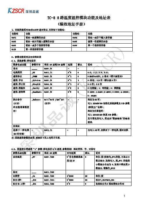
功能码功能功能码功能0x01读取一组逻辑位状态0x04读取一或多个输入寄存器0x02读取一组开关输入逻辑位状态0x05强置一位逻辑位状态0x03读取一或多个保持寄存器0x06置一个保持寄存器0x10置一串保持寄存器2参数功能说明及对应地址表21系统参数
TC-8 8 路温度温控模块功能及地址表
(编程地址手册)
2.4、运行参数:(可写的参数)掉电不保存
2.4.1、通道采样数值:(只读),数据类型:无符号字
通道
地址:16 进制 /10 进制
通道 1
0x800 /2048
通道 2
0x801 /2049
通道 3
0x802 /2050
通道 4
0x803 /2051
温控模块触摸屏程序编写方法
温控模块触摸屏程序编写方法温控模块触摸屏程序是一种用于控制温度的软件程序,它可以通过触摸屏幕来实现对温度的控制和调节。
在编写温控模块触摸屏程序时,需要遵循以下步骤:1. 确定程序的功能和需求在编写温控模块触摸屏程序之前,需要先确定程序的功能和需求。
这包括需要控制的温度范围、温度调节精度、温度显示方式等。
只有明确了程序的功能和需求,才能更好地进行程序设计和编写。
2. 设计程序界面程序界面是用户与程序交互的重要界面,需要设计一个简洁、直观、易于操作的界面。
在设计程序界面时,需要考虑到用户的使用习惯和操作方式,尽可能地减少用户的操作步骤和操作难度。
3. 编写程序代码在编写程序代码时,需要根据程序的功能和需求,选择合适的编程语言和开发工具。
常用的编程语言包括C、C++、Java等,常用的开发工具包括Visual Studio、Eclipse等。
在编写程序代码时,需要注意代码的可读性、可维护性和可扩展性,尽可能地避免代码冗余和重复。
4. 调试程序在编写完程序代码后,需要进行程序调试。
程序调试是指通过模拟实际使用环境,检查程序的功能和性能是否符合要求。
在程序调试过程中,需要注意程序的稳定性和可靠性,尽可能地避免程序崩溃和数据丢失。
5. 发布程序在程序调试通过后,需要将程序发布到目标设备上。
在发布程序时,需要注意程序的安装和配置,尽可能地避免程序安装和配置出现问题。
同时,需要提供用户手册和技术支持,帮助用户更好地使用程序。
温控模块触摸屏程序编写需要遵循以上步骤,才能保证程序的功能和性能符合要求。
同时,需要不断地进行程序优化和改进,以满足用户的需求和期望。
- 1、下载文档前请自行甄别文档内容的完整性,平台不提供额外的编辑、内容补充、找答案等附加服务。
- 2、"仅部分预览"的文档,不可在线预览部分如存在完整性等问题,可反馈申请退款(可完整预览的文档不适用该条件!)。
- 3、如文档侵犯您的权益,请联系客服反馈,我们会尽快为您处理(人工客服工作时间:9:00-18:30)。
温控模块触摸屏程序编写方法
随着电子技术的不断发展,温控模块越来越广泛地应用于各种工业生产和日常生活中。
温控模块的核心是控制器,而控制器的核心是程序。
本文将介绍温控模块触摸屏程序编写方法。
一、程序框架
程序框架是程序编写的基础,也是程序的骨架。
程序框架应该包含以下几个部分:
1.初始化部分:包括硬件初始化和软件初始化。
硬件初始化主要是对各种外设的初始化,如IO口、定时器、串口等;软件初始化主要是对程序中各种变量的初始化,如温度变量、设定温度变量等。
2.主程序部分:包括读取温度、设定温度、控制加热等功能。
主程序部分应该是程序的核心,也是程序的最复杂部分。
3.显示部分:包括显示温度、设定温度、控制状态等信息。
显示部分应该简单明了,易于用户理解。
4.中断服务程序部分:包括定时器中断、串口中断等。
中断服务程序部分应该能够及时响应各种中断事件,保证程序的稳定性和可靠性。
二、程序设计
程序设计是程序编写的关键,也是程序的灵魂。
程序设计应该遵循以下几个原则:
1.简单明了:程序应该简单明了,易于理解和维护。
2.可靠稳定:程序应该可靠稳定,不易出现故障和错误。
3.高效节能:程序应该高效节能,能够充分利用硬件资源,尽量减少功耗。
4.易于扩展:程序应该易于扩展,能够方便地添加新的功能和模块。
三、程序调试
程序调试是程序编写的必要环节,也是程序的保障。
程序调试应该遵循以下几个原则:
1.分步调试:程序调试应该分步进行,逐步验证程序的正确性。
2.数据监测:程序调试应该对程序中各种变量进行监测,及时发现问题。
3.错误记录:程序调试应该及时记录错误信息,便于排查和修复。
4.性能测试:程序调试应该进行性能测试,验证程序的稳定性和可靠性。
四、总结
温控模块触摸屏程序编写方法是一个综合性的问题,需要从程序框架、程序设计和程序调试三个方面进行综合考虑。
只有在这三个方面都做好了,才能编写出高质量的温控模块触摸屏程序。