NEC钽电容规格书
贴片钽电容封装规格表
贴片钽电容封装规格表
贴片钽电容封装规格表
1. 贴片钽电容封装规格
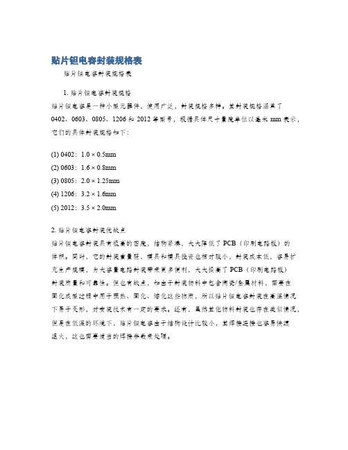
贴片钽电容是一种小型元器件,使用广泛,封装规格多样。
其封装规格涵盖了0402、0603、0805、1206和2012等型号,根据具体尺寸量度单位以毫米mm表示,它们的具体封装规格如下:
(1) 0402:1.0 × 0.5mm
(2) 0603:1.6 × 0.8mm
(3) 0805:2.0 × 1.25mm
(4) 1206:3.2 × 1.6mm
(5) 2012:3.5 × 2.0mm
2. 贴片钽电容封装优缺点
贴片钽电容封装具有极高的密度,结构紧凑,大大降低了PCB(印刷电路板)的
体积。
同时,它的封装重量轻,模具和模具投资也相对较小,封装成本低,容易扩充生产规模,为大容量电路封装带来更多便利,大大提高了PCB(印刷电路板)
封装质量和可靠性。
但也有缺点,如由于封装物料中包含陶瓷/金属材料,需要在
固化成型过程中用于预热、固化、熔化这些物质,所以贴片钽电容封装在高温情况下易于变形,对安装技术有一定的要求。
还有,虽然其他物料封装也存在类似情况,但是在低温的环境下,贴片钽电容由于结构设计比较小,其焊接连接也容易快速
退火,这也需要适当的焊接参数来处理。
钽电容封装大全及技术参数
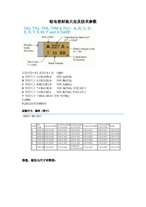
钽电容封装大全及技术参数长的话是+-0.2 ,宽是+-0.1 高(MM)A 型的尺寸3.2 X1.6 X1.6 俗称: A(3216)B 型的尺寸3.5 X2.8 X1.9 俗称: B(3528)C 型的尺寸6.0X 3.2X 2.6 俗称: C(6032)D 型的尺寸7.3 X4.3 X2.9 俗称: D(7343) 厚度2.9英寸E 型的尺寸7.3 X4.3 X4.1 俗称: E(7343) 厚度4.1英寸V 型的尺寸7.3X 6.1 X3.45 俗称: V(7361)J (1608)P (2012)也就是0805的封装尺寸:毫米(英寸)容值、耐压与尺寸对照表:电感封装一般包括贴片与插件。
1.功率电感封装以骨架的尺寸做封装表示。
贴片用椭柱型表示方法如5.8(5.2)×4就表示长径为5.8mm短径为5.2mm高为4mm的电感(贴片电感封装)。
插件用圆柱型表示方法如φ6×8就表示直径为6mm高为8mm的电感。
只是它们的骨架一般要通用,要不就要定造。
2.普通线性电感、色环电感与电阻电容的封装都有一样的表示,贴片用尺寸表示如0603、0805、0402、1206等(贴片电感封装)。
插件用功率表示如1/8W、1/4W、1/2W、1W等。
3.至于二极管插件一般是DO-41;贴片封装就多SOD-214、LL-34。
4.三极管插件一般是To92;贴片封装就多SOT-23、SOT-223等不能尽说,由于自动化封装变得多种多样。
发光二极管:颜色有红、黄、绿、蓝之分,亮度分普亮、高亮、超亮三个等级,常用的封装形式有三类:0805、1206、1210二极管:根据所承受电流的的限度,封装形式大致分为两类,小电流型(如1N4148)封装为1206,大电流型(如IN4007)暂没有具体封装形式,只能给出具体尺寸:5.5 X 3 X 0.5电容:可分为无极性和有极性两类,无极性电容下述两类封装最为常见,即0805、0603;而有极性电容也就是我们平时所称的电解电容,一般我们平时用的最多的为铝电解电容,由于其电解质为铝,所以其温度稳定性以及精度都不是很高,而贴片元件由于其紧贴电路版,所以要求温度稳定性要高,所以贴片电容以钽电容为多,根据其耐压不同,贴片电容又可分为A、B、C、D四个系列,具体分类如下:类型封装形式耐压A 3216 10VB 3528 16VC 6032 25VD 7343 35V拨码开关、晶振:等在市场都可以找到不同规格的贴片封装,其性能价格会根据他们的引脚镀层、标称频率以及段位相关联。
NEC-钽电容
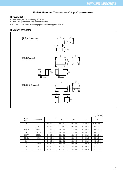
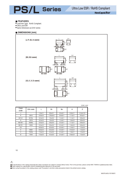
Case EIA codeL W 1W 2H Z Code J – 1.6 ± 0.10.8 ± 0.10.6 ± 0.10.8 ± 0.10.3 ± 0.15P 2012 2.0 ± 0.2 1.25 ± 0.20.9 ± 0.1 1.1 ± 0.10.5 ± 0.1A2 (U)3216L 3.2 ± 0.2 1.6 ± 0.2 1.2 ± 0.1 1.1 ± 0.10.8 ± 0.2A 3216 3.2 ± 0.2 1.6 ± 0.2 1.2 ± 0.1 1.6 ± 0.20.8 ± 0.2B3 (W)3528L 3.5 ± 0.2 2.8 ± 0.2 2.2 ± 0.1 1.1 ± 0.10.8 ± 0.2B2 (S)3528 3.5 ± 0.2 2.8 ± 0.2 2.2 ± 0.1 1.9 ± 0.20.8 ± 0.2C2– 6.0 ± 0.2 3.2 ± 0.2 2.2 ± 0.1 1.4 ± 0.1 1.3 ± 0.2C 6032 6.0 ± 0.2 3.2 ± 0.2 2.2 ± 0.1 2.5 ± 0.2 1.3 ± 0.2V –7.3 ± 0.2 4.3 ± 0.2 2.4 ± 0.1 1.9 ± 0.1 1.3 ± 0.2D73437.3 ± 0.24.3 ± 0.22.4 ± 0.12.8 ± 0.21.3 ± 0.2E/SV Series Tantalum Chip Capacitors(Unit: mm)s FEATURESq Lead-free Type. In conformity to RoHS.q Offer a range of small, high-capacity models.q Succeed to the latest technology plus outstanding peformance.s DIMENSIONS [mm]s STANDARD C-V VALUE REFERENCE BY CASE CODEESV A0J 106MDC rated voltage in voltsCapacitance toleranceCapacitance (pF)First two digits represent significant figures.Third digit specifies number of zeros to follow.M K : ±20%: ±10%Case code E/SV Series0E : 2.5 V, 0G : 4 V, 0J : 6.3 V, 1A : 10 V, 1C : 16 V, 1D : 20 V, 1E : 25 V, 1V : 35 V TE [Bulk][Tape and Reel]ESVA0J106M 8RPacking OrientationTape widthR : Cathode on the Side of Sproket Hole Part number of BulkTape and Reel8 : 8 mm (J, P, A2, A, B3, B2 case)12 : 12 mm (C2, C, V, D case)TE : 180 mm reelTL ESVA0J106M 8REIndicates 330mm reel Tape and ReelTL : 330 mm reelφφφs PART NUMBER SYSTEM[ ] :Under development2.5V 0E4V 0G6.3V 0J10V 1A16V 1C 20V 1D 25V 1E 35V 1V 0.470.681.01.52.23.34.76.8101522334768100150220330470680474684105155225335475685106156226336476686107157227337477687P P J, P A P, A2, A, [J]A2, A A2, A A, B3A, B3, B2B2, [A]B3, B2, C C2, C, [B2]C, D C, D DA2A2A2A2P, A2, A A, B3A2, A, B3, B2B2B2C C2, C, D D DA A A2, A A A, B2B2, [B3]C C C, D DP J, P J, P P, A2J, P, A2, A A2, A P, A2, A, B2B3, [P]A, B3, B2, [A2]B3, B2, [A]B2, C2, C, [B3]B2, C2, C C, V, D, [C2]V, D DA A P, A2, AA, [P]A B3, B2, [A2]C, [B2]C D D [D]P J J J, P, A J, P, A2J, P, A2, A P, A2, AP, A2, A, B3, B2A, B3, [A2]A, B3, B2, C B2, C2B2, C2, C, [B3]C C, V, D D DPJ J, P P P, A2, A P, A2, A P, A2, A, B3A, B3A, B3, B2, C2B2, C2B2, C C, V D D JP, A2P, A2P, A2, A A B3, B2A, B3, C2B2, C2B2, C C, D µU R Fs MARKINGSThe standard marking shows capacitance, DC rated voltage, and polarity.[J case Marking Code][P case Marking Code]µµ[J case] (ex. 4.7 F / 6.3 V)µ[A2, A cases] (ex. 10 F / 6.3 V)µs PERFORMANCE CHARACTERISTICSTest Conditions : Conform to IEC 60384-1at 85°C at 125°C at 85°C at 120 Hz at 100 kHzsolder dip : 260°C, 5sec solder reflow : 260°C,10sec 25V 16V 33V35V 22V 46V16V 10V 20V20V 13V 26V6.3V 4V 8V10V 6.3V 13V2.5V 1.6V3.3V4V 2.5V 5.2VLower than 2 times initial specification (P, J case) or 1.25times initial specification Parts shall be temperature cycled over a temperature range of -55 to +125°C, five times continuously as follow.Step 1: -55 °C, 30±3min.Step 2: room temp. , 10 to 15min.Step 3: 125 °C, 30±3min.Step 4: room temp, 10 to 15min.Refer to Standard Ratings at 40°Cat 90 to 95% RH 500 hourat 85°C: Rated voltage at 125°C: Derated voltage 2000 hourStrength : 4.9N Time : 10±0.5sec.(two directions)0.125C •V(µA) or 6.25µA,which ever is greaterLower than initial specificationLower than initial specification PERFORMANCE TEST CONDITIONOperating temperature Rated voltage (V.dc)Derated voltage (V.dc)Surge voltage (V.dc)Capacitance Capacitance tolerance DC Leakage Current (L.C) Dissipation FactorEquivalent Series Resistance-55°C to +125°C ITEMSurge voltage test 0.47 µF to 680 µF L.C Refer to Standard RatingsRefer to Standard Ratings Refer to Standard Ratingsat 120 Hz±20% or ±10% (P,J case: ±20%)λ0=1% / 1000 hourVisual:There shall be no evidence of mechanical damageRefer to Standard RatingsRefer to Standard RatingsRefer to Standard Ratingsat 85°C: Rated voltageat 125°C: Derated voltage 2000 hour Lower than initial specificationLower than initial specification Endurance Damp heatFailure RateTerminal StrengthLower than 1.5 times initialspecificationVoltage:Rated voltage for 5min.Temperature : 85±2°CApplied voltage : Surge voltage Series resistance : 33 ohm Duration of surge : 30±5 sec Time between surge : 5.5min.Number of cycle : 10000.01C • V(µA) or 0.5 µA , whichever is greaterLower than initial specificationLower than initial specificationCapacitance change DF(%)Lower than initial specificationRapid change of temperatureResistance to Soldering heat Characteristic at high and low temperatureLower than initial specification -55°C+85°C +125°CNot to exceed -20% (P, J case)or -12%Not to exceed +20% (P, J case)or +12%Lower than initial specification Refer to Standard RatingsRefer to Standard RatingsNot to exceed +20% (P, J case)or +15%0.1C •V(µA) or 5µA,which ever is greater Step 1: 25±2°CStep 2: -55 °C Step 3: 25±2°CStep 4: 125 °C-30-30-30-3————Derate voltage at 85°C at more[U T ] = [U R ] –[U R ] – [U C ]40Reference : Derated voltage (85 to 125°C)[U T ]: Derated voltage at operating temperature [U R ]: Rated voltage[U C ]: Derated voltage at 125°C T : Ambient temperature(T–85)s STANDARD RATINGS。
钽电容的介绍和选型
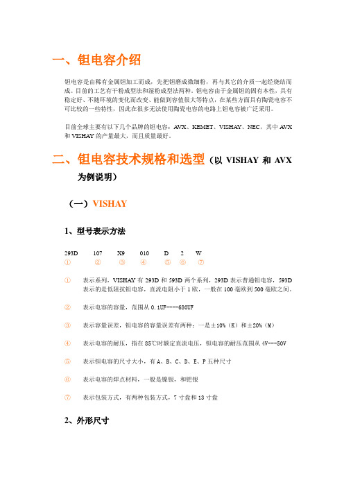
一、钽电容介绍钽电容是由稀有金属钽加工而成,先把钽磨成微细粉,再与其它的介质一起经烧结而成。
目前的工艺有干粉成型法和湿粉成型法两种。
钽电容由于金属钽的固有本性,具有稳定好、不随环境的变化而改变、能做到容值很大等特点,在某些方面具有陶瓷电容不可比较的一些特性,因此在很多无法使用陶瓷电容的电路上钽电容被广泛采用。
目前全球主要有以下几个品牌的钽电容:A VX、KEMET、VISHAY、NEC,其中A VX 和VISHAY的产量最大,而且质量最好。
二、钽电容技术规格和选型(以VISHAY和A VX为例说明)(一)VISHAY1、型号表示方法293D 107 X9 010 D 2 W①②③④⑤⑥⑦①表示系列,VISHAY有293D和593D两个系列,293D表示普通钽电容,593D表示的是低阻抗钽电容,直流电阻小于1欧,一般在100毫欧到500毫欧之间。
②表示电容的容量,范围从0.1UF----680UF③表示容量误差,钽电容的容量误差有两种:一是±10%(K)和±20%(M)④表示电容的耐压,指在85℃时额定直流电压,钽电容的耐压范围从4V---50V⑤表示钽电容的尺寸大小,有A、B、C、D、E、P五种尺寸⑥表示电容的焊点材料,一般是镍银,和钯银⑦表示包装方式,有两种包装方式,7寸盘和13寸盘2、外形尺寸3、容量与电压和尺寸的范围关系表293D普通系列593D低阻系列(通用低阻钽电容为100UF----470UF)4、包装(一)A VX1、型号表示方法TAJ C 100 K 010 R①②③④⑤⑥①表示系列,A VX有TAJ和TPS两个系列,TAJ表示普通钽电容,TPS表示的是低阻抗钽电容,直流电阻小于1欧,一般在100毫欧到500毫欧之间,特殊的可以低到40毫欧。
②表示钽电容的尺寸大小,有A、B、C、D、E、Y、V六种尺寸③表示电容的容量,范围从0.1UF----1000UF④表示容量误差,钽电容的容量误差有两种:一是±10%(K)和±20%(M)⑤表示电容的耐压,指在85℃时额定直流电压,钽电容的耐压范围从4V---50V⑥表示包装方式,有两种包装方式,7寸盘和13寸盘2、外形尺寸3、容量与电压和尺寸的范围关系表TAJ普通系列备注:标红颜色的是该容量、该电压下所对应的首选尺寸TPS低阻系列(通用低阻钽电容为100UF----470UF)备注:在A VX的超低阻值的规格表示上,还表明了具体阻值的数字,例如:TPSD107K010R0100,其中0100就是直流电阻的大小-------100毫欧。
NEC 钽电容规格书
Test Conditions : Conform to IEC 60384-1
TEST CONDITION Derate voltage at 85°C at more 16V 12.8V 20V at 85°C at 105°C at 85°C at 120 Hz Voltage: Rated voltage for 5min. at 120 Hz at 100 kHz Temperature : 85±2°C Applied voltage : Surge voltage Series resistance : 33 ohm Duration of surge : 30±5 sec Time between surge : 5.5min. Number of cycle : 1000 Step 1: 25±2°C 0 Step 2: –55 –3 °C Step 3: 25±2°C 0 Step 4: 105–3 °C Parts shall be temperature cycled over a temperature range of –55 to +105°C, five times continuously as follow. 0 Step 1: –55 –3 °C, 30±3min. Step 2: room temp. , 10 to 15min. 0 °C, 30±3min. Step 3: 105–3 Step 4: room temp, 10 to 15min. Reflow soldering method 240°C, 10 sec.Max. *2 at 40°C at 90 to 95% RH 500 hour at 85°C at rated voltage 1000 hour at 105°C at Derated voltage 1000 hour at 85°C: rated voltage at 105°C: derated voltage Strength : 4.9N Time : 10±0.5sec. (two directions) at 100 kHz Conform to IEC60384–1 *1
钽电容规格书模板(更新)
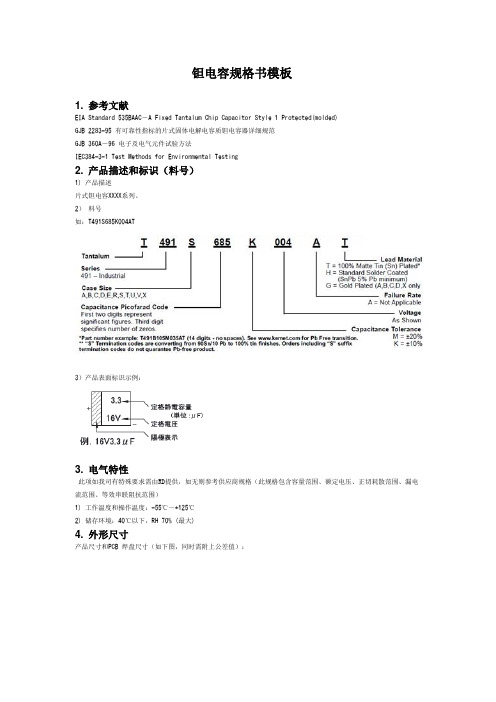
钽电容规格书模板1. 参考文献EIA Standard 535BAAC-A Fixed Tantalum Chip Capacitor Style 1 Protected(molded)GJB 2283-95 有可靠性指标的片式固体电解电容质钽电容器详细规范GJB 360A-96 电子及电气元件试验方法IEC384-3-1 Test Methods for Environmental Testing2. 产品描述和标识(料号)1) 产品描述片式钽电容XXXX系列。
2)料号如:T491S685K004AT3)产品表面标识示例:3. 电气特性此项如我司有特殊要求需由RD提供,如无则参考供应商规格(此规格包含容量范围、额定电压、正切耗散范围、漏电流范围、等效串联阻抗范围)1) 工作温度和操作温度:-55℃~+125℃2) 储存环境:40℃以下,RH 70% (最大)4. 外形尺寸产品尺寸和PCB 焊盘尺寸(如下图,同时需附上公差值):5. 检验和测试程序5.1 测试条件如无特别规定,检验和测试的标准大气环境条件如下:a. 环境温度:25±10℃;b. 相对湿度:50±30%;c. 气压:86KPa ~106KPa如果对测试结果有异议,则在下述条件下测试:a. 环境温度:25±1℃;b. 相对湿度:50±2%;c. 气压:86KPa ~ 106KPa5.2 外观检查a. 检查设备:20 倍放大镜;5.3 电性测试5.3.1 等效串联电阻(ESR)a. 测试频率:100±5KHz;5.3.2 电容量(C)a. 测试频率:120±5Hz;b. 测试信号:1000mVc. 直流偏压:1.5V5.3.3 tanδ 值a. 测试频率:120±5Hz;b. 测试信号:1000mVc. 直流偏压:1.5V5.3.4 漏电流(I0)a. 在25℃条件下,加直流额定电压,充电时间最长为5min;b. 电流值随着时间而下降,到某一终值时达到较稳定状态,记录该电流值。
钽电容封装大全及技术参数

钽电容封装大全及技术参数A 型的尺寸3.2 X1.6 X1.6 俗称: A(3216)B型的尺寸3.5 X2.8 X1.9 俗称: B(3528)C型的尺寸6.0X 3.2X 2.6 俗称: C(6032)D 型的尺寸7.3 X4.3 X2.9 俗称: D(7343) 厚度2.9英寸E 型的尺寸7.3 X4.3 X4.1 俗称: E(7343) 厚度4.1英寸V 型的尺寸7.3X 6.1 X3.45 俗称: V(7361)J(1608)P(2012)也就是0805的贴片钽电容封装~~~~~~~~~~~~~~~~~~~~~~~~~~~~~~~~~~~~~~~~~~~~~~~~~~~~~~~~~~~~~~~~~~~~~~~~~~~~~~~~~~~~~·贴片钽电容封装:封装尺寸:毫米(英寸)~~~~~~~~~~~~~~~~~~~~~~~~~~~~~~~~~~~~~~~~~~~~~~~~~~~~~~~~~~~~~~~~~~~~~~~~~ ~~~~~~~~~~~~~~~~~~~~~~~~~~~~~~~~~~~~~~~~~~~~~~~~~~~~~~~~~~~~~~~~~~~~~~~~~ ~~~~~~~~~~~~~~~~~~~~~~·······贴片钽电容封封装及规格和参数资料2009-03-05 14:13分类:转载字号:大大中中小小贴片钽电容简述贴片钽电容(以下简称钽电容)作为电解电容器中的一类。
广泛应用于各类电子产品,特别是一些高密度组装,内部空间体积小产品,如手机、便携式打印机。
钽电容是一种用金属钽(Ta)作为阳极材料而制成的,按阳极结构的不同可分为箔式和钽烧粉结式两种。
在钽粉烧结式钽电容中,又因工作电解质不同,分为固体电解质钽电容(Solid Tantalum)和非固体电解质钽电容。
其中,固体钽电解电容器用量最大。
钽电容由于使用金属钽做介质,不需要像普通电解电容那样使用电解液。
钽电容全参数介绍及使用技巧
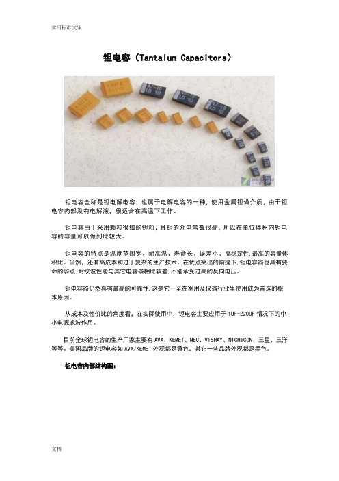
钽电容(Tantalum Capacitors)钽电容全称是钽电解电容,也属于电解电容的一种,使用金属钽做介质,由于钽电容内部没有电解液,很适合在高温下工作。
钽电容由于采用颗粒很细的钽粉,且钽的介电常数很高,所以在单位体积内钽电容的容量可以做到比较大。
钽电容的特点是温度范围宽、耐高温、寿命长、误差小、高稳定性,最高的容量体积比。
当然,还有高成本和过于复杂的生产技术。
在优点突出的前提下,钽电容器也具有要命的弱点,耐纹波性能与其它电容器相比较差,不能承受过高的反向电压。
钽电容器仍然具有最高的可靠性.这是它一至在军用及仪器行业里使用成为首选的根本原因。
从成本及性价比的角度看,在实际使用中,钽电容主要应用于1UF-220UF情况下的中小电源滤波作用。
目前全球钽电容的生产厂家主要有AVX、KEMET、NEC、VISHAY、NICHICON、三星、三洋等等。
美国品牌的钽电容如AVX/KEMET外观都是黄色,其它一些品牌外观都是黑色。
钽电容内部结构图:钽电容内部等效电路:钽电容MARK标识:钽电容主要参数:1、容值范围:钽电容的容值参数范围一般在0.47UF-680UF,不同厂家根据工艺能力,稍微有区别。
一般情况下钽电容使用参数范围在1UF-220UF左右。
从下面图表可以看出,钽电容在超过100K以上频率时,电容参数急剧减小。
所以,钽电容一般情况下只适合低频情况下中大电流滤波。
2、额定电压:一般钽电容的额定电压范围在4V-50V,考虑到125度环境需要做降额使用,参考下表。
在常规-55°C to + 125°C环境下,额定电压需要降额到2/3左右使用。
具体降额可以用下列公式计算:Vmax=( 1-(T-85)/125)×VRVmax是最大工作电压T 是要求的工作温度VR是额定电压值得注意的是上述公式只适用于高阻抗的放电电路。
同时,上述公式并没有考虑交流分量和浪涌的影响,因此当使用温度较高时,必须使用更大的降额电压才能稳定可靠地工作。
- 1、下载文档前请自行甄别文档内容的完整性,平台不提供额外的编辑、内容补充、找答案等附加服务。
- 2、"仅部分预览"的文档,不可在线预览部分如存在完整性等问题,可反馈申请退款(可完整预览的文档不适用该条件!)。
- 3、如文档侵犯您的权益,请联系客服反馈,我们会尽快为您处理(人工客服工作时间:9:00-18:30)。
Z
Z
Z
Z
Unit : mm (inch)
L
W1
W2
H
Z
1.6 ± 0.1 (0.061±0.004)
PDF 文件使用 "pdfFactory Pro" 试用版本创建
Correct Use of NeoCapacitor (Please Read)
[Notes] l Be sure to read "Notes on Using The NeoCapacitor" (p29 - p32) and "Cautions" (p35) before
Packaging ………………………………………………………………………………… 27
Notes on Using The NeoCapacitor …………………………………………………… 29
PDF 文件使用 "pdfFactory Pro" 试用版本创建
What's NeoCapacitor
2.2 to 1000
±20
330 to 680
±20
DC Leakage Current ( A)
0.1 CV or 3, (J case, 10 A) whichever greater
0.1 CV or 3, whichever greater
Dissipation Factor (%)
4 to 10
Dimensions
J, P, A2 and A case
L
W1
B3, B2 and V case
L
W1
C2, C and D case
L
W1
Z
Case code J P A2 A B3 B2 C2 C V D
Z
EIA code –
2012 3216L 3216H
– 3528
– 6032
– 7343
Applications
DC / DC converter Suppression of oscillation for general purpose regulator Video camera Portable cassette / CD player Personal handy phone Game machine
l Special: This quality grade is intended for special applications that have common requirements, such specific industrial fields. Devices with a "special" quality grade are designed, manufactured, and tested using a more stringent quality assurance program than that used for "standard" grade devices. There is a high possibility that failure or malfunction of the device when being used for applications in this category will cause harm to persons or damage to property, or create negative effects or problems in the wider community.
Conductive polymer used for electrolyte
( ) is superior in insulating the damaged portion in comparison with the manganese oxide (used in conventional tantalum capacitor)
(S • m–1)
Anode (tantalum)
Dielectric (tantalum oxide)
Conductive glue Silver paste Graphite layer Conductive polymer
10 4
Conductive polymer
10 3
TCNQ
(organic semiconductor)
l Standard: This quality grade is intended for applications in which failure or malfunction of the device is highly unlikely to cause harm to persons or damage to property, or be the source of any negative effects or problems in the wider community.
CONTENTS
What's NeoCapacitor ……………………………………………………………………… 3
PS/L Series (Ultra-low ESR) ……………………………………………………………… 4
PS/G Series (Single Digit ESR) ……………………………………………………… 19
l Specific: Devices with a "specific" quality grade are designed, manufactured, and tested using a quality assurance program that is designated by the customer or that is created in accordance with the customer's specifications. There is an extremely high possibility that failure or malfunction of the device when being used for applications in this category will cause harm to persons or damage to property, or create serious problems in the wider community. Customers who use NEC TOKIN's products for these "specific" applications must conclude an individual quality agreement and/or development agreement with NEC TOKIN. A quality assurance program designated by the customer must also be determined in advance.
leakage current or short-circuiting. It is therefore important to make sufficient allowances for redundant wiring in the circuit design.
[Quality Grades] NEC TOKIN devices are classified into the following quality grades in accordance with their application (for details of the applications, see p35). The quality grade of all devices in this document is "standard"; the devices in this document cannot be used for "special" or "specific" quality grade applications. Customers who intend to use a product or products in this document for applications other than those specified under the "standard" quality grade must contact an NEC TOKIN sales representative in advance (see the reverse side of the cover for contact details).
Lead-free / Conform to RoHs
NeoCapacitor has the same structure as a conventional chip tantalum capacitor. It has a low-resistance cathode of conductive polymer as a substitute for manganese dioxide of a conventional capacitor. It features high permissible ripple current and effective noise reduction in a high frequency application with its ultra low ESR (equivalent series resistance). NeoCapacitor is manufactured in the factories certified by the International standards, the ISO9001 and the QS-9000. Conformity to RoHs is available by Lead-free plating.