RF5189
WIFI模块-硬件设计资料

WIFI模块硬件设计规格书版本: 1.0目录1 模块总体介绍(Gerneral introduction) (4)1.1 概述及实物图片(Description) (4)1.2 应用领域(Application) (6)1.3 产品特性 (Main feature) (6)2 模块电气特性(Electric Characteristics) (8)2.1 极限条件(Absolute Maximum Ratings) (8)2.2 工作条件(Recommended Operate Range) (8)2.3 电气特性(General Electric Characteristics)............................... (8)2.4 拼脚定义(Pin Assignment and Description) (9)3 模块应用设计指导(Application note) (14)3.1 功能框图(Function Block description) (14)3.2 工作状态描述(state descriptions) (14)3.3 硬件应用接口概述 (15)3.4 电源和驱动应用接口 (16)3.4.1 电源和驱动管脚定义 (16)3.4.2 主电源供电特性Vbat (17)3.4.3 备用电池RTC................................................................................. ........................... (18)3.4.4 开关机及复位(Power ON/OFF and Reset) (19)3.4.5 充电输入口VCHGIN............................ ................................. .. (20)3.4.6 充电输出口VCHGOUT........................... ................................. . (21)3.4.7 电池检测专用ADC口ADC3/BAT_ID ........................... .. (21)3.4.8 4路LDO输出.................................................... .. (22)3.4.9 LED-驱动 (22)3.4.10 KEY_ LED-驱动 (23)3.4.11电源电路参考设计 (23)3.5 按键接口........................................... . (24)3.6 语音接口........................................... (25)3.6.1模拟音频差分输入主MIC0和辅助MIC1.................................................................................. . (25)3.6.2 模拟音频差分输出受话器REC (26)3.6.3 模拟音频差分输出喇叭SPK (26)3.7 UART 接口 (27)3.8 IIC 接口 (28)3.9 LCD IO驱动为2.8V SPI 接口 (28)3.10 LCD IO驱动为1.8V SPI 接口 (29)3.11 USB 接口..................................... . (30)3.12 SIM 卡接口 (31)3.13 T-F卡接口 (32)3.14 F M 接口 (34)3.15 BT 接口 (34)3.16 通用GPIO接口 (35)3.17 中断口EINT (35)3.18 模拟输入ADC (35)3.19 射频天线接口 (36)4硬件设计指南 (37)4.1 PCB板布局说明 (37)4.2 PCB 关键走线说明......................................................... (37)5 机械特性 (38)5.1 模块机械尺寸 (38)5.2 模块产品 Top-View 视图.......................................... (39)5.3模块供电要求及接法 (41)5.4下载软件 (41)5.5模块开机 (41)5.6 RF测试连接 (41)6 附录 (42)6.1 射频指标 (42)6.2 通信专用术语 (42)1 模块总体介绍1.1 概述及实物图片GW01_GSM&WIFI是一款GSM/GPRS/WIFI无线四频(GSM850/GSM900/DCS1800/PCS1900)工业模块,可以覆盖全球通用GSM频段。
巴别与债务——从德里达解构主义视角看翻译

人 文社 科
巴 别 与 债务
从德 里达解构主义视 角看翻译
山东大学外国语学院 王海燕
[ 摘 要] 作为解构主义的代表人 物, 雅克 ・ 德里达及其 思想在 西方翻译史、 哲学史上都 占有重要地 位, 解构主义也对人类整个知识领 域产生 了深远 的影响。本文论述 了 解构主义的起源和基本观点 , 并通过德 里达《 巴别通天塔 》 一文,了解构主义视 角下 , 对译文和译 者地位的重视 , 对译者主体性的充分肯定, 并简要分析 了其影响和局 限性。 [ 关键 词] 结构主义 解构主义 不可译性 延异 雅克 ・ 德里达 是法 国的解构主义思潮 的领军人 物 , 他以《 字语言 文 学》 《 、声音与现象》 《 、书写与差异》 三部书的出版 , 宣告 了解构主义的确 立 。尽管解 构主义的理论十分抽象难懂 , 有的甚至互相矛盾 , 对其理解 也莫衷一是 , 但不可否认 , 它对社会科学 、 哲学 、 翻译研究等领域都产生 了深远的影 响。《 巴别通天塔》 是德里达 18 年发表的论文 , 95 他借用圣 经里面的巴别塔寓言 , 把上帝刻 成一个解构者 , 将解构主义与翻译联 系起来 , 为翻译既是必需的 , 认 却又是不能完成的。这篇文章题 目本身 就因其多重含义而无法精确翻译 ,而这正是德里达解构主义不可译论 的例证演示之一。
一
、
开始 , 他不仅解构通天塔 , 解构天下将要共用 的语言 , 也解构了 自己。 在 这 一瞬间 , 上帝把翻译这项工作 强加 于人类 , 同时 又禁止人类 翻译( 德 里达 ,9 5 o上帝禁止 翻译 以防止人类 的联合 , 18 但如果不翻译 , 上帝的 律法就不能为人类所知 。 这样一来 , 翻译就变成 了一项必需而又无从实 现 的工作。债 务伴随翻译而产生了。 方面 , 由于对译 作的需要 , 原作与上 帝都 不得不负债于 翻译 者。 德里达指 出 , 原作要求翻译 , 哪怕 没有翻译者 , 哪怕没有人适 于执 行这 个命令 , 原作 的结构 中同时存在着要求和欲望。 但 这个结构就是生命与 生存的关系。 在这一点上 , 他继承了本雅明在《 译者的任务》 中提到的观 点, 即作品是 否具有可译性 , 取决于作 品本身是否需求并呼唤翻译。德 里达认为 , 如果原文 的解构要求 翻译 ,那么原文一开始就负债于翻译 者, 原文是第一个负债者 。另一方面 , 翻译 的忠实性使翻译者不得不负 债于原作 与上帝 。 威尼斯商人》 《 中夏洛克忠实于契约 , 要从安东尼奥身 上取一磅 肉, 但是他 失败的原因就是 “ 实” 忠 ——他不 能保证从安东 尼 奥身上割肉的时候 , 不留一滴 血。翻译也是一样 , 忠实是一个陷阱 , 翻译 包含了一个无法偿还的债务 。犹太人夏洛克要求“ 公正”jsc )基督 (ute , i 徒一方坚持“ 仁慈” m r ) ( e y 。德里达认为 , c 这里“ 公正” 可转喻为 “ 忠实 ” 与“ 可译” “ ,仁慈 ” 可转喻为“ 不忠实 ” 不可译” 以仁慈调剂公正 , 与“ , 实 际上 是 以“ 不忠 实 ” 调剂 “ 忠实 ” 以“ , 不可 译 ” 剂“ 调 可译 ” 单 继 刚 , ( 20 ) 0 7 。只有这样 , 才能完成翻译和转换 。 瓦尔 特 ・ 本雅明认为 , 翻译成 为原作的来世 (f rf)通过异种 繁 at le , ei 殖, 原语吸收新元素 , 充分扩张其表达力 , 也就更趋成熟 了。德里达继承 了这一观点 , 认为 翻译是 一个不断解构 、 建构 的过 程, 通过引人的外来 语言元素颠覆 、 原文语 言的秩 序。但 他更强调了不 可译性 , 拆解 认为 由 于语言不断游走 ,翻译 仅能在短暂的时空里面促进 两个语 言之 间的接 触, 然后它们又分道扬镳 了。他的《 巴别通天塔》 文中就暗示了这一 一 点, 他反复强调翻译 既是必需的 , 却又无从完成 。 他指出 , 上帝以 自己可 译而又不可译的专有名 词提供 了一个 普遍公 理 , 但上帝恰巧也在 同一 时 间内限制了公理的普遍性 : 言的明澈遭取缔 , 语 单义境界无从 实现。 结果翻译变成了律令 、 职责 、 债务 , 可是这项债务 , 我们已无力清偿 。
2.4G+1W+双向智能功率放大器参考资料
2.4G 1W 双向智能功率放大器参考资料(带图片)“务必(双向放大),否则没意义”参考资料1:在两个或多个网络互连时,无线局域网的低功率与高频率限制了其覆盖范围,为了扩大覆盖范围,可以引入蜂窝或者微蜂窝的网络结构或者通过增大发射功率扩大覆盖半径等措施来实现。
前者实现成本较高,而后者则相对较便宜,且容易实现。
现有的产品基本上通信距离都比较小,而且实现双向收发的比较少。
本文主要研究的是距离扩展射频前端的方案与硬件的实现,通过增大发射信号功率、放大接收信号提高灵敏度以及选择增益较大的天线来实现,同时实现了双向收发,最终成果可以直接应用于与IEEE802.11b/g兼容的无线通信系统中。
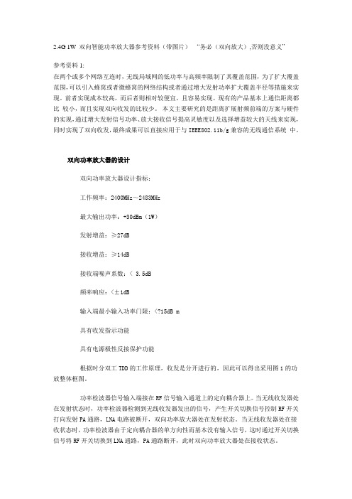
双向功率放大器的设计双向功率放大器设计指标:工作频率:2400MHz~2483MHz最大输出功率:+30dBm(1W)发射增益:≥27dB接收增益:≥14dB接收端噪声系数:< 3.5dB频率响应:<±1dB输入端最小输入功率门限:<?15dB m具有收发指示功能具有电源极性反接保护功能根据时分双工TDD的工作原理,收发是分开进行的,因此可以得出采用图1的功放整体框图。
功率检波器信号输入端接在RF信号输入通道上的定向耦合器上。
当无线收发器处在发射状态时,功率检波器检测到无线收发器发出的信号,产生开关切换信号控制RF开关打向发射PA通路,LNA电路被断开,双向功率放大器处在发射状态。
当无线收发器处在接收状态时,功率检波器由于定向耦合器的单方向性而基本没有输入信号,这时通过开关切换信号将RF开关切换到LNA通路,PA通路断开,此时双向功率放大器处在接收状态。
下面介绍重点部位的设计:发射功率放大(PA)电路发射功率放大电路的作用是将无线收发器输入功率放大以达到期望输出功率。
此处选择单片微波集成电路(MMIC)作为功率放大器件,并采用两级级联的方式来同时达到最大输出功率与增益的要求。
前级功率放大芯片选择RFMD公司的RF5189,该芯片主要应用在IEEE802.11b WLAN、2.4GHz ISM频段商用及消费类电子、无线局域网系统、扩频与MMDS系统等等。
2.4G射频双向功放电路设计

2.4G射频双向功放电路设计在两个或多个网络互连时,无线局域网的低功率与高频率限制了其覆盖范围,为了扩大覆盖范围,可以引入蜂窝或者微蜂窝的网络结构或者通过增大发射功率扩大覆盖半径等措施来实现。
前者实现成本较高,而后者则相对较便宜,且容易实现。
现有的产品基本上通信距离都比较小,而且实现双向收发的比较少。
本文主要研究的是距离扩展射频前端的方案与硬件的实现,通过增大发射信号功率、放大接收信号提高灵敏度以及选择增益较大的天线来实现,同时实现了双向收发,最终成果可以直接应用于与IEEE802.11b/g兼容的无线通信系统中。
双向功率放大器的设计双向功率放大器设计指标:工作频率:2400MHz~2483MHz最大输出功率:+30dBm(1W)发射增益:≥27dB接收增益:≥14dB接收端噪声系数:< 3.5dB频率响应:<±1dB输入端最小输入功率门限:<?15dB m具有收发指示功能具有电源极性反接保护功能根据时分双工TDD的工作原理,收发是分开进行的,因此可以得出采用图1的功放整体框图。
功率检波器信号输入端接在RF信号输入通道上的定向耦合器上。
当无线收发器处在发射状态时,功率检波器检测到无线收发器发出的信号,产生开关切换信号控制RF开关打向发射PA通路,LNA电路被断开,双向功率放大器处在发射状态。
当无线收发器处在接收状态时,功率检波器由于定向耦合器的单方向性而基本没有输入信号,这时通过开关切换信号将RF 开关切换到LNA通路,PA通路断开,此时双向功率放大器处在接收状态。
下面介绍重点部位的设计:发射功率放大(PA)电路发射功率放大电路的作用是将无线收发器输入功率放大以达到期望输出功率。
此处选择单片微波集成电路(MMIC)作为功率放大器件,并采用两级级联的方式来同时达到最大输出功率与增益的要求。
前级功率放大芯片选择RFMD公司的RF5189,该芯片主要应用在IEEE802.11b WLAN、2.4GHz ISM频段商用及消费类电子、无线局域网系统、扩频与MMDS 系统等等。
RF-性能差

切换成功率 HEBBSC04
越区覆盖
李振宇
未闭环
3度
5度-6度
10月26日 靠河村G-2
切换成功率 HEBBSC04
越区覆盖
李振宇
未闭环
3度
5度-6度
10月26日 靠河村G-3 10月26日 光明村G-1
切换成功率 HEBBSC04 切换成功率 HEBBSC04
越区覆盖 越区覆盖
李振宇 李振宇
未闭环 未闭环
建议覆盖TA
现在方位 角
调整后后 方位角
调整后目的
塔高
备注
5
2 调整下倾角为控制 覆盖,调整方位角 是为了吸收小区或 平房的话务量,深
5
1.4
4
1.5
6
40
6
120
6 7、8
3
260
调整下倾角为控制 覆盖
47
为了越区不让调
8 4、5
1
30
38
8
140
8 8 6 4
270 30 控制覆盖下压天 线,调整方位角覆 255 盖小区,做深度覆 40
越区覆盖
侯彦琳
未闭环
7度
8度
切换成功率 切换成功率 切换成功率
越区覆盖 越区覆盖 越区覆盖
侯彦琳 侯彦琳 侯彦琳
未闭环 未闭环 未闭环
0 0 0
8 7 7
2012-10-29 无法调整 广和酒店G-1 10月29日 朝阳镇新立村G-1 10月29日 朝阳镇新立村G-2
无线接通率 HEBBSC10 切换成功率 HEBBSC10 切换成功率 HEBBSC10
成高子东升村G-3 振兴屯G-1 振兴屯G-2 振兴屯G-3 市五院G-3 2011平安村G-1 广和酒店G-1 成高子红鲜G-3 翠柳公园G-3 朝阳永胜村G-1 前兴隆水厂G-2 王岗镇东G-2
PID控制的BGA自动定位装置系统设计

0 引言
随着科技产 品功能 的 日趋 强大 , I C封装 的接脚数
越来越多 , 小 I 缩 C尺 寸 的要 求 变 得 更 为 迫 切 , 自动 化
1 基 于 P C 的步进 电机传 动 系统 L
步进 电机是一种将 电脉冲转化为角位移 的执行机 构, 它可直接用数字信号控制 , 无需反馈 , 可开环工作 , 无累积定位误差 , 控制精度高 , 被广泛应用于数字控制
果, 使生 产效率 得到 了提高 。 关 键词 :智能 PD 球 栅 阵列 I
中图分类 号 :T 2 5 P 1
P C 图像 检测 L
精密 定位
结b t a t Ai n tte ds d a tg so r dt n lI a k gn e h oo y, e g sr c : mig a h ia v na e fta io a C p c a ig tc n lg i . .-p o lg me ta c rc o rain n c u a y,lw p r t n e iin y a d o o e ai f ce c n o
ag rtm n P C o to oc n tu tte ta s sins se .Th o o io fte sse i r sa c e n h tu t r ft e p n il lo i h i L c nrlt o sr c h rn miso y tm e c mp st n o h ytm s e e rh dl d t e sr cue o r cp e i a h i p ooy e i d sg e rttp s e in d;tu e ac i cue b sd o GA ma e d tcin a r cs l n n y tm spo o e .Th e uto x e me t h st r ht t r ae n B h e i g ee t ndp e ieai me ts se i rp s d o g er sl fe p r i ns v rf ste c re t s n e sblt ft es se ,a l a h p rt n lefcso e BGA uo t o ao nprcia p l ain o ei e h orcnesa d fa ii yo y tm i i h swel steo e ai a f t ft o e h a tmai lc tri a tc a pi t sfr c l c o e ha cn rd cie e ce c n n ig p o u t f in y. v i
综合运用动态监测资料确定单砂体剩余油

2 Te t g C mp n , g n led a a g . si o a y Da a g Oi i ,D g n ,Ti j 0 2 0 hn ) n fl a i 3 0 8 ,C ia nn
Jn 06 u 2 0
综 合 运 用 动 态 监 测 资 料 确 定 单 砂 体 剩 余 油
平 , 贺 静 申海 华 , ,徐 建 ,杨 士荣 贾 岩
0 2 0 ( . 津 工 程 职业 技 术 学 院 ,天津 3 0 8 ; 2 大港 油 田测 试 公 司 ,天津 大港 30 8 ) 1天 0 20 .
*
摘要 :阐述 了综合运用 动态监测 资料 确定单砂体剩余油分布 规律的方法 。该 方法涉及 2个关键 技术 , 一是 产量劈 分技 术; 二是 剩余 油分布技术 。产量劈分技术很好地解决 了水 驱砂 岩油 藏高含水 后期产量劈分的问题 , 该项技 术充分利 用了 动态监测 资料 , 与常规方法相 比, 具有 与油藏开发资料结合更 紧密 、 与油 田实际更接近的特点 ; 剩余 油分布技术选用 随机
中 图分 类 号 :TE 2 . 3 l 2 2 文 献标 识 码 :A
De e m i a i n o sdu lO i n I di i u lS n dy wih Dy a i on t r n t tr n to fRe i a li n v d a a d Bo t n m c M io i g Da a H E Jn SHEN ih a , XU in pn z YAN G h—o g , JA n ig , Ha— u 2 Ja - ig , S irn z I Ya 2
5g射频器件封装集成技术

5g射频器件封装集成技术The development of 5G technology has revolutionized the telecommunications industry, leading to significant advancements in speed, latency, and overall network performance. At the heart of this transformation lies the intricate packaging and integration of 5G radio-frequency (RF) components. These components, essential for signal transmission and reception, must be meticulously designed and assembled to ensure optimal performance within the 5G spectrum.5G技术的发展彻底改变了电信行业,带来了速度、延迟和网络性能方面的重大进步。
在这一变革的核心,是5G射频(RF)器件的精细封装和集成技术。
这些器件对于信号的传输和接收至关重要,必须精心设计并组装,以确保在5G频谱内实现最佳性能。
The packaging of 5G RF devices involves the integration of multiple components, including antennas, filters, amplifiers, and other circuitry, into a single, compact unit. This process requires precision and expertise, as each component must be placed accurately and interconnected to minimize signal loss and maximize efficiency. The materials used in the packaging process are also crucial, as they must be able to withstand the high frequencies and temperatures associated with 5G operation.5G射频器件的封装涉及将多个组件(包括天线、滤波器、放大器和其他电路)集成到一个紧凑的单元中。
- 1、下载文档前请自行甄别文档内容的完整性,平台不提供额外的编辑、内容补充、找答案等附加服务。
- 2、"仅部分预览"的文档,不可在线预览部分如存在完整性等问题,可反馈申请退款(可完整预览的文档不适用该条件!)。
- 3、如文档侵犯您的权益,请联系客服反馈,我们会尽快为您处理(人工客服工作时间:9:00-18:30)。
Product DescriptionOrdering InformationTypical ApplicationsFeaturesFunctional Block DiagramRF Micro Devices, Inc.7628 Thorndike RoadGreensboro, NC 27409, USA Tel (336) 664 1233Fax (336) 664 0454Optimum Technology Matching® AppliedSi BJT GaAs MESFET GaAs HBTSi Bi-CMOS SiGe HBTSi CMOS InGaP/HBTGaN HEMTSiGe Bi-CMOSPWR SENBIAS1GND RF IN NC V R E G 2B I A S 2G N DRF OUTRF OUTV C C 2V R E G 1V C C 1V C C 2RF51893V , 2.45GHz LINEAR POWER AMPLIFIER•IEEE802.11B WLAN Applications •2.5GHz ISM Band Applications •Wireless LAN Systems •Commercial and Consumer Systems •Portable Battery-Powered Equipment •Spread-Spectrum and MMDS SystemsThe RF5189 is a linear, medium-power, high-efficiency amplifier IC designed specifically for battery-powered WLAN applications such as PC cards, mini PCI, and compact flash applications. The device is manufactured on an advanced Gallium Arsenide Heterojunction Bipolar T ransistor (HBT) process, and has been designed for use as the final RF amplifier in 2.5GHz WLAN and otherspread-spectrum transmitters. The device is provided in a 12-pin QFN package with a backside ground. The RF5189 is designed to maintain linearity over a wide range of supply voltage and power output. The RF5189 is designed to reduce end-product BOM count by integrat-ing all matching circuitry onto the chip.•Single Power Supply 3.0V to 5.0V •+30dBm Saturated Output Power •25dB Small Signal Gain •High Linearity•2400MHz to 2500MHz Frequency RangeRF51893V , 2.45GHz Linear Power Amplifier RF5189 PCBA Fully Assembled Evaluation BoardShaded lead is pin 1.Package Style: QFN, 12-Pin, 3x39查询RF5189供应商RF5189Absolute Maximum RatingsParameterRatingUnitSupply Voltage-0.5 to +6.0V DC Power Control Voltage (V REG )-0.5 to 3.5V DC Supply Current 600mA Input RF Power+10dBm Operating Ambient T emperature -40 to +85°C Storage Temperature -40 to +150°CMoisture sensitivityJEDEC Level 2ParameterSpecification Unit ConditionMin.Typ.Max.Overall-11b SignalT=25°C, V CC =3.0V , V REG =2.7V ,Freq=2450MHzFrequency Range2400 to 2500MHzMaximum Linear Output PowerWith 802.11B modulation (11Mbit/s) and meeting 802.11B spectral mask.V CC =3.0V 2122dBm V CC =5.0V24dBm Linear Efficiency 24%Small Signal Gain 232527dB P IN =-7dBmSecond Harmonic-35dBc 802.11B Adjacent ChannelPower-38-32dBc P OUT =21dBm, V CC =3.0V Alternate Channel Power -56-52dBc P OUT =21dBm, V CC =3.0V Isolation30dB In “OFF” state, P IN =-5.0dBm Input Return Loss 9.515.0dB 50Ω reference Output VSWR2:1 1.5:150Ω reference Power Detect Voltage1.72.1 2.4V P 0=21dBmPower DownV REG “ON” 2.12.73.0V Voltage supplied to control input; device is “ON”V REG “OFF”0.5VVoltage supplied to control input; device is “OFF”Power SupplyOperating Voltage 3.0 to 5.0V Current Consumption10µA V REG =0V100160mA No RF input, V CC =3.0V , and V REG =2.7V 220270mA P OUT =21dBm, V CC =3.0V , and V REG =2.7V V REG Current (Total)510mA V CC =3.0V 1015mAV CC =5.0VESD sensitive device.RF Micro Devices believes the furnished information is correct and accurate at the time of this printing. However, RF Micro Devices reserves the right to make changes to its products without notice. RF Micro Devices does not assume responsibility for the use of the described product(s).Refer to “Handling of PSOP and PSSOP Products” on page 16-15 for special handling information.RF5189RF5189Theory of OperationThe RF5189 is a two-stage device with a nominal gain of 25dB in the 2.4GHz to 2.5GHz ISM band. The RF5189 is designed primarily for IEEE802.11B WLAN applications where the available supply voltage and current are limited. This amplifier will operate to (and below) the lowest expected voltage made available by a typical PCMCIA slot in a laptop PC, and will maintain required linearity at decreased supply voltages.The RF5189 requires only a single positive supply of 3.0V nominal (or greater) to operate to full specifications. Power control is provided through two bias control input pins (VREG1 and VREG2), but in most applications these are tied together and used as a single control input.There is no external matching required on the input and output of the part, thus allowing minimal bill of material (BOM) parts count in end applications. Both the input and the output of the device are DC-blocked.For best results, the PA circuit layout from the evaluation board should be copied as closely as possible, particularly the ground layout and ground vias. Other configurations may also work, but the design process is much easier and quicker if the layout is copied from the RF5189 evaluation board. Gerber files of our designs are available on request.The RF5189 is not a difficult part to implement, but care in circuit layout and component selection is always advisable when designing circuits to operate at 2.5GHz. The choke inductors on VCC2 and BIAS2GND should be chosen so that they are parallel self-resonant at the frequency of operation. In addition, the supply side of the choke inductor on VCC2 should be bypassed with a capacitor that is series self-resonant at the frequency of operation.In practice, VCC1 and the supply side of the choke on VCC2 will be tied to the same supply. It is important to isolate VCC1 from other RF and low-frequency bypass capacitors on this supply line. This can be accomplished using a suit-ably-long transmission line which is RF shorted on the other end as described above. Ideally the length of this line will be a quarter wavelength, but it only needs to be long enough so that the effects of other supply bypass capacitors on the VCC1 line are minimized. If board space is a concern, this isolation can also be accomplished with an RF choke inductor or ferrite bead.The RF5189 has primarily been characterized with a voltage on VREG1 and VREG2 of 2.7V DC. However, the RF5189 will operate from a wide range of control voltages. If you prefer to use a control voltage that is significantly different than 2.7V DC, contact RFMD Sales or Applications Engineering for additional data and guidance.RF5189 Evaluation Board SchematicJ1RF INVREG1RF5189Evaluation Board LayoutBoard Size 1.10" x 1.85"Board Thickness 0.032”, Board Material FR-4RF5189RF5189RF5189PCB Design RequirementsPCB Surface FinishThe PCB surface finish used for RFMD’s qualification process is electroless nickel, immersion gold. T ypical thickness is 3µinch to 8µinch gold over 180µinch nickel.PCB Land Pattern RecommendationPCB land patterns are based on IPC-SM-782 standards when possible. The pad pattern shown has been developed and tested for optimized assembly at RFMD; however, it may require some modifications to address company specific assembly processes. The PCB land pattern has been developed to accommodate lead and package tolerances.PCB Metal Land PatternAA ADimensions in mm.Pin 9A = 0.69 x 0.28 (mm) Typ.B = 0.28 x 0.69 (mm) Typ.C = 1.45 (mm) Sq.Figure 1. PCB Metal Land Pattern (Top View)RF5189PCB Solder Mask PatternLiquid Photo-Imageable (LPI) solder mask is recommended. The solder mask footprint will match what is shown for the PCB Metal Land Pattern with a 3mil expansion to accommodate solder mask registration clearance around all pads. The center-grounding pad shall also have a solder mask clearance. Expansion of the pads to create solder mask clearance can be provided in the master data or requested from the PCB fabrication supplier.A = 0.79 x 0.38 (mm) Typ.B = 0.38 x 0.79 (mm) Typ.C = 1.55 (mm) Sq.Figure 2. PCB Solder Mask Pattern (Top View)Thermal Pad and Via DesignThe PCB Metal Land Pattern has been designed with a thermal pad that matches the exposed die paddle size on the bottom of the device.Thermal vias are required in the PCB layout to effectively conduct heat away from the package. The via pattern has been designed to address thermal, power dissipation and electrical requirements of the device as well as accommodating routing strategies.The via pattern used for the RFMD qualification is based on thru-hole vias with 0.203mm to 0.330mm finished hole size on a 0.5mm to 1.2mm grid pattern with 0.025mm plating on via walls. If micro vias are used in a design, it is suggested that the quantity of vias be increased by a 4:1 ratio to achieve similar results.。