OMRON光电传感器技术手册
Omron光电传感器选型指南说明书

HUMAN MACHINEINTERFACESENERGYMANAGEMENTSOLUTIONSFA COMPONENTSMACHINE VISIONSYSTEMSUV CURINGSYSTEMSCX-400CY-100EX-10EX-20EX-30EX-40CX-440EQ-30EQ-500MQ-WRXRT-610Hardly affected by colorThe color or size of the object does not affect its sensingperformance.Hardly affected by backgroundThe sensor does not detectthe background beyond theset distance since it is ofdistance adjustable type.RobustIts robust enclosure is made of die-cast zinc alloy.High-speed response time: 1 msIt can be used on a high speed assembly line.BASIC PERFORMANCEWaterproof IP67 (IEC)The equipment on which the sensor is mounted can bewashed without any problem.ENVIRONMENTAL RESISTANCENote: H owever, take care that if it is exposed to water splashesduring operation. It may detect a water drop itself.Insusceptible to dustThe sensing performanceis less affected by dust asit does not depend on theincident light intensity.has a specular surface.Adjustable Range Reflective Photoelectric SensorRX-LS200344FIBER SENSORSLASER SENSORS PHOTO-ELECTRIC SENSORS AREA SENSORS SAFETY LIGHT CURTAINS /SAFETY COMPONENTS PRESSURE / FLOW SENSORS INDUCTIVE PROXIMITY SENSORS PARTICULAR USE SENSORS SENSOR OPTIONS SIMPLE WIRE-SAVING UNITS WIRE-SAVING SYSTEMSMEASURE-MENT SENSORS STATIC CONTROL DEVICES LASER MARKERS PLC HUMAN MACHINE INTERFACES ENERGY MANAGEMENT SOLUTIONS FACOMPONENTS MACHINE VISION SYSTEMSUVCURINGSYSTEMSEX-Z CX-400CY-100EX-10 EX-20EX-30EX-40CX-440EQ-30EQ-500RX RT-6105 m cable length type5 m 16.404 ft cable length type (standard: 3 m 9.843 ft ) is also available for NPN output type.Model No.: RX-LS200-C5Accessory• MS-RX-1 (Sensor mounting bracket)Narrow-view slit mask• OS-RXL-□Protective tubeTwo M4 (length 16 mm 0.630 in )hexagon-socket-head bolts are attached.056 222 38 18*********************SEN TRONIC AG345Adjustable Range Reflective Photoelectric Sensor RX-LS200FIBERSENSORSLASERSENSORSPHOTO-ELECTRICSENSORSAREASENSORSSAFETY LIGHTCURTAINS /SAFETYCOMPONENTSPRESSURE /FLOWSENSORSINDUCTIVEPROXIMITYSENSORSPARTICULARUSESENSORSSENSOROPTIONSSIMPLEWIRE-SAVINGUNITSWIRE-SAVINGSYSTEMSMEASURE-MENTSENSORSSTATICCONTROLDEVICESLASERMARKERSPLCHUMANMACHINEINTERFACESENERGYMANAGEMENTSOLUTIONSFACOMPONENTSMACHINEVISIONSYSTEMSUVCURINGSYSTEMSEX-ZCX-400CY-100EX-10EX-20EX-30EX-40CX-440EQ-30EQ-500RXRT-610I/O circuit diagram Wiring diagramSymbols … D : Reverse supply polarity protection diodeZ D : Surge absorption zener diodeTr : NPN output transistor±10 %RX-LS200NPN output type 056 222 38 18*********************SEN TRONICAGAdjustable Range Reflective Photoelectric SensorRX-LS200346FIBER SENSORS LASER SENSORS PHOTO-ELECTRIC SENSORSAREA SENSORS SAFETY LIGHT CURTAINS /SAFETY COMPONENTS PRESSURE / FLOW SENSORS INDUCTIVE PROXIMITY SENSORS PARTICULAR USE SENSORS SENSOR OPTIONS SIMPLE WIRE-SAVING UNITS WIRE-SAVING SYSTEMSMEASURE-MENT SENSORS STATIC CONTROL DEVICES LASER MARKERS PLC HUMAN MACHINE INTERFACES ENERGY MANAGEMENT SOLUTIONS FACOMPONENTS MACHINE VISION SYSTEMS UVCURINGSYSTEMSEX-Z CX-400CY-100EX-10EX-20EX-30EX-40CX-440EQ-30EQ-500RX RT-610I/O circuit diagramWiring diagramNote: T he output does not incorporate a short-circuit protection circuit.Do not connect it directly to a power supply or a capacitive load.Symbols … D : Reverse supply polarity protection diodeZ D : Surge absorption zener diode Tr : PNP output transistorto 24 V DCSensing fields• Setting distance: 200 mm 7.874 in (Horizontal)• Setting distance: 200 mm 7.874 in (Vertical)• Setting distance: 150 mm 5.906 in (Horizontal)• Setting distance: 150 mm 5.906 in (Vertical)• Setting distance: 150 mm 5.906 in with slit mask (Vertical)• Setting distance: 150 mm 5.906 in with slit mask(Horizontal)0.3940.394Left Center in )S e t t i n g d i s t a n c e L (m m i n Up Center Operating point ℓ (mm in )0.3940.394S e t t i n g d i s t a n c e L (m m in Left Center in)0.1570.157S e t t i n g d i s t a n c e L (m mi nUp Center in )0.1570.157S e t t i n g d i s t a n c e L(m m i nLeft Center Operating point ℓ (mm in )0.1570.157S e t t i n g d i s t a n c e L (m m i nUp Operating point ℓ (mm in )0.1570.157S e t t i n g d i s t a n c e L (m m i nCorrelation between sensing object size and sensing range0.787 1.575 2.362 3.1503.937 in , 7.874 in , each, with white non-glossy 1.969 × 1.969 in ).side length a (mm in )S e n s i n g r a n g e L (m m i n D i s t a n c e L (m m i n RX-LS200-P PNP output type056 222 38 18*********************SEN TRONIC AG347Adjustable Range Reflective Photoelectric Sensor RX-LS200FIBERSENSORSLASERSENSORSPHOTO-ELECTRICSENSORSAREASENSORSSAFETY LIGHTCURTAINS /SAFETYCOMPONENTSPRESSURE /FLOWSENSORSINDUCTIVEPROXIMITYSENSORSPARTICULARUSESENSORSSENSOROPTIONSSIMPLEWIRE-SAVINGUNITSWIRE-SAVINGSYSTEMSMEASURE-MENTSENSORSSTATICCONTROLDEVICESLASERMARKERSPLCHUMANMACHINEINTERFACESENERGYMANAGEMENTSOLUTIONSFACOMPONENTSMACHINEVISIONSYSTEMSUVCURINGSYSTEMSEX-ZCX-400CY-100EX-10EX-20EX-30EX-40CX-440EQ-30EQ-500RXRT-610Correlation between material (50 × 50 mm 1.969 × 1.969 in) and sensing range200 mm 7.874 in100 mm 3.937 in50 mm 1.969 inWhitenon-glossypaperPlywoodCardboardCeramiccircuitboardGraynon-glossypaper(Lightness:3)BlackrubbeMirrorThese bars indicate the sensing rangewith respective objects when thedistance adjuster is set at the sensingrange of 200 mm 7.874 in, 100 mm3.937 in and 50 mm 1.969 in long,each, with white non-glossy paper.(GreenmaskedsurfaceGlassepoxyprintedcircuitboardSensingrangeL(mminWiring• The output of RX-LS200-P does not incorporate a short-circuit protection circuit. Do not connect it directly to apower supply or a capacitive load.Others• Do not use during the initial transient time (50 ms) afterthe power supply is switched on.Mounting• The tightening torque should be 1.17 N·m or less.• Care must be taken regarding the sensor mountingdirection with respect to the object’s direction of movement.Do not make the sensordetect an object in thisdirection because it maycause unstable operation.Sensing object Sensing object Sensing objectintersection of the “ ”mark on the lens faceand the “ ” line.• When detecting a specular object (aluminum or copperfoil) or an object having a glossy surface or coating,please take care that there are cases when the objectmay not be detected due to a small change in angle,wrinkles on the object surface, etc.• When a specular body is present below the sensor, usethe sensor by tilting it slightly upwards to avoid wrongoperation.Use conditions to comply with CE Marking• Following work must be done in case of using thisproduct as a CE marking (European standard EMCDirective) conforming product.Ensure that the shield is connected to 0 V or the actualground.• In case of connecting a sensor to power supply 0 V by usinga shield (piping, etc.)• In case of grounding by using a shield (piping, etc.)Note: The shield (piping, etc.) must be insulated.• If a specular body is present in the background, wrongoperation may be caused due to a small change in theangle of the background body. In that case, install thesensor at an inclination and confirm the operation withthe actual sensing object.• Do not install the sensor at a distance of less than 50 mm1.969 in from the object because the sensing is unstablein this range.Correct Correct Incorrect056 222 38 18*********************SEN TRONICAGAdjustable Range Reflective Photoelectric SensorRX-LS200348FIBER SENSORS LASER SENSORS PHOTO-ELECTRIC SENSORS AREA SENSORSSAFETY LIGHT CURTAINS /SAFETY COMPONENTS PRESSURE / FLOW SENSORSINDUCTIVE PROXIMITY SENSORS PARTICULAR USE SENSORSSENSOR OPTIONS SIMPLE WIRE-SAVING UNITS WIRE-SAVING SYSTEMSMEASURE-MENT SENSORS STATIC CONTROL DEVICES LASER MARKERS PLC HUMAN MACHINE INTERFACES ENERGY MANAGEMENT SOLUTIONS FACOMPONENTS MACHINE VISION SYSTEMSUVCURINGSYSTEMSEX-Z CX-400CY-100EX-10 EX-20EX-30EX-40CX-440EQ-30EQ-500RX RT-610Distance adjustmentSensorRX-LS200 RX-LS200-PProtective tube (Optional)PT-RX500 PT-RX1000MS-RX-1Sensor mounting bracket (Accessory)Assembly dimensions• Follow only steps 1 and 2 respectively. Since the sensing point may change depending on the sensing object, be sure to check the operation with the actual sensing object.<When a sensing object is approaching / moving away from the sensor><When a sensing object moves horizontally to the sensor>) hexagon-socket-AdjustersAdjusting procedure056 222 38 18*********************SEN TRONIC AG。
OMRON FS-V10 系列光电传感器说明书

54Digital LEDBar-graph LEDDual monitoring systemThe FS-V10 Series features both a digital LED indicator, whichnumerically displays the received light intensity, and a bar LED, which shows the level of detectionDescriptionFeaturesq An Industry-first dual monitoring system q Auto and manual calibrationq 20-bit concurrent processing chip q High accuracy and high powerqWire-saving 0-line or 1-line connection systemDetecting DistanceThrubeam – Up to 3,600 mm (with lens)Diffuse-reflective – Up to 300 mmDefinite-reflective – Up to 14 mmAutomatic SET buttonFS01SeriesHigh AccuracyFibreoptic Sensors<FS-V10 Series>NEW 20-bit concurrentprocessing chip + 12-bit A/D converter The FS-V10 Series features a newlydeveloped 20-bit concurrent processing chip.This chip can concurrently process12 types of control including calculation of received light intensity “dual monitor display ”, and hold display ”. Compared to general-purposeHigh Accuracy Fibreoptic SensorsAmplifier VariationsHybrid Calibration Type:FS-V10 Series•Dual monitoring function withbar LED and digital display•Hybrid calibration with Auto SETbutton and manual adjustmentbuttonOne-touch Calibration Type:FS-T Series•Fully-automatic calibration byDetects down to 0.01 mm dia wire withDetects target at the industry longestHigh Accuracy Fibreoptic SensorsSUPER TURBO ModeTURBO Mode200 mm300 mmFINE Mode100 mmModel: FU-66From ultra-high precision to ultra-high power:A single unit covers every applicationThe FS-V10 Series offers three levels of detection to Small targetReceived light quantity: LargeLarge targetReceived light quantity: SmallArea detection fibre unitHigh Accuracy Fibreoptic SensorsUnstable operating conditions can be discovered at a glance using Bar LED indicatorsThe bar LED indicates detection stability using a 7-level bar LED.The bar LED shows when maintenance is required at a glance, which is difficult to notice with the digital display.Low excess gainOne LED does not lightduring light beam reception.1-line systemSpace advantageHigh Accuracy Fibreoptic Sensors)l a t i g i d ,l a u n a m +h c u o t -e n O (n o i t a r b i l a c d i r b y H ti n u n i a M ti n u n o i s n a p x e e n i l -1ti n u n o i s n a p x e e n i l -011V -S F 21V -S F 01V -S F .1P11V -S F P21V -S F —DE L d e R )O B R U T R E P U S (s m 1/)O B R U T (s µ005/)E N I F (s µs m 7.1o t s µ014.2)e l b a t c e l e s -h c t i w s (N O -K R A D /N O -T H G I LHigh Accuracy Fibreoptic Sensorsno i t a r b i l a c l a u n a M t i n u n i a M ti n u n o i s n a p x e e n i l -1es n o p s e r d e e p s -h g i H ti n u n o i s n a p x e e n i l -01M -S F 2M -S F H1M -S F 0M -S F P 1M -S F P 2M -S F ——DE L d e R DE L d e R DE L d e R DE L d e R )e l b a t c e l e s -h c t i w s (O B R U T /E N I F ,)r o t a c i d n i h t i w (r e m m i r t n r u t -8,)E N I F (s µ052)O B R U T (s µ005,)E N I F (s µ052)O B R U T (s µ005,)E N I F (s µ02)O B R U T (s µ05s m 2.1o t s µ014.1.x a m x u l 000,02:t h g i l n u S ,.x a m x u l 000,01:p m a l t n e c s e d n a c n I 55+o t 01-°C55+o t 01-°C55+o t 01-°C55+o t 01-°Ce t a n o b r a c y l o P :r e v o C e t a n o b r a c y l o P :r e v o C /y d o B e t a n o b r a c y l o P :r e v o C /y d o B et a n o b r a c y l o P :r e v o C /y d o B g57.x o r p p A g04.x o r p p A g02.x o r p p A g02.x o r p p A The response speed varies depending on the number of expansion units connected.Only the FS-T1/M1 provide stability outputs. Stability outputs for the FS-T2/T0/M2/M0 are output from the FS-T1/M1 or FS-R0.Power to the FS-T2/T0/M2/M0 is supplied through the FS-V11/V1/T1/M1 or FS-R0.1-line connection amplifiers reduce wiring Up to 16 expansion units can be connected to a single main unit and can be freely combined.Expansion units+FS-T1G :Green LED light source FS-M1H :High-speed response FS-V12:Hybrid calibration FS-T2:One-touch calibration FS-M2:Manual calibration FS-R0FS-T0FS-M0Connector unit0-lineexpansion-units0-line connection units eliminate wiring and labourThe innovative 0-line connection system only requires an FS-R0 connector unit and a cable with a MIL connector for wiring. The units can be easily connected to an I/O card of a PLC (programmable controller) or special board. Units can be freely combined to suit the application.Board InputDC power supplyPLC Cable with MIL connectorFS-V10Terminal block unitHigh Accuracy Fibreoptic SensorsFU-77FU-67FU-66ZFU-63ZFU-35FZFU-12A single-core fibre exposed to excessive bending will easily break.The 217-core fibre is hardly affected by exces-sive bending.Ready for immediate useArmoured ToughFlexprovides a cost and labour savings by eliminating the need for protective tubing.More flexible than conventional spiral fibresToughFlex will not break even when sharply bent.More flexible than conventional spiral fibres.Standard FibreToughFlex Fibre PrincipleKeyence has developed the toughest fibre unit series by bundling multiple core fibres of 66 µm diameter. These fibres will work normally without any malfunction even when they are bent to a minimum radius or when they are Keyence has also maintained a long detecting distance while using this unique design. Including focused small spot model, area detection model, ultra-long detecting distance model, and thin sleeve models, every application can be improved with maintenance efficiency.Plus, the latest armoured model is sheathed by a flexible stainless steel jacket to protect the fibre from daily wear ToughFlex fibre variationsToughFlex Fibre FeaturesT oughFlex will not break even when sharply bent.FU-67G/77GHigh Accuracy Fibreoptic Sensors FS01ToughFlex Fibres [Patent pending]:FU-67/77/35FZ/4FZ/5FZ/63Z/66Z/12Fibres with a minimum bend radius of 2 mm retain light intensity even when folded. These innovative fibres can be routed just like an electric wire, enabling installation anywhere.High-flex Fibres: FU-45X/48/49X/59/65X/68/69X/78/79 These fibres, which provide higher flexibility than an electric wire, can endure repeated bends. The bendradius of 4 mm makes fibre routingeasier and saves mountingspace.Compact Definite Reflective Fibres: These fibres are excellent for detection in tight spaces such as being embedded in a robot arm or on a conveyor. Detection is almost unaffected by target backgrounds.Area Detection Fibre: FU-12The FU-12, which provides a detecting area 10 mm wide, is suitable for detecting vibrating targetsor minute targets. A target assmall as 1.2 mm in diametercan be accurately detected.Fibre Unit Selection Guide (major models only)High Accuracy Fibreoptic SensorsFeaturesDetecting distance 1. (mm)Smallest 2. detectable object Minimum bend radius640760(3600)320ø0.03 mmø0.03 mmR25 mmR4 mmLong-detecting distanceA minimum bend radius of 4 mm300370150Lens F-1, F-2, F-4Lens F-1, F-2, F-4Fibre Unit Selection ChartHigh Accuracy Fibreoptic SensorsFeaturesDetecting distance 1. (mm)Smallest 2.detectable object Minimum bend radiusModel Weight(Approx.)2003001001602408020281270110ø0.01 mm (gold wire)R25 mmSuitable for positioning0.2 mm spot diameter when used with F-2HA 0.4 mm spot diameter when 4g18g4g 6g Free-cutFree-FU-23X FU-25FU-21XFU-35FALens F-2HALensHigh Accuracy Fibreoptic SensorsFeaturesDetecting distance 1. (mm)Smallest 2.detectable object Minimum bend radius3 (Centre of detecting distance)3 (Centre of detecting distance)3 (Centre of detecting distance)6 ±16 ±16 ±10 to 40 to 40 to 40 to 14 (Centre of detecting distance)0 to 14 (Centre of detecting distance)ø0.3 mm (gold wire)ø0.08 mm (copper wire)R25 mmR10 mmø0.01 mm (gold wire)Almost unaffected by target colour and backgroundAlmost unaffected by target background, side-by-sidedetection available Almost unaffected by target colour and background, long-High Accuracy Fibreoptic Sensorsdr a d n a t S tn a t s i s e r -t a e H ,f o o r p l i O fo o r p l a c i m e h C 053°ep y t C 003°ep y t C 081°ep y t C 501°ep y t C 07+o t 04-°C :77,76,21-U F (05+o t 04-°,C :93-U F 001+o t 03-°)C 053+o t 03-°C .1003+o t 04-°C .1081+o t 06-°C .1501+o t 04-°C 07+o t 03-°C,c i t s a l P :e r b i F :h t a e h S e n e l y h t e y l o P )s s a l g :93-U F (,s s a l G :e r b i F la r i p s l e e t s -s s e l n i a t S :h t a e h S eb u t ,c i t s a l P :e r b i F :h t a e h S no b r a c o r o u l F gn i t a o c r e m y l o p ,c i t s a l P :e r b i F :h t a e h S en e l y p o r p y l o P ,c i t s a l P :e r b i F n o l f e T :h t a e h S1. Ambient temperature varies depending on the distance from the tip or a fibre unit. Refer to "Dimensions". The ambient temperature for the FU-87 and 88 is in dry condition.ConfigurationFeature Model FINE TURBO SUPERTURBO ModelDetecting distance (mm)Applicable fibre units FU-35FA(Z)FU-35FA(Z)FU-7F,8640026022022018008005404404403600100067055055036002.FU-77, 77G FU-78FU-84CFU-7F,860 to 20 with beam spotdiameter of 4 mm15 ±2 with beam spot diameter of 0.5 mmImproves the stability for the minute target detection.Space-saving, side-view type F-3HAF-4HAF-11.NEW When using the F-1 at a temperature of 70°C or more, specify the "Heat-resistant F-1"."3600" is assumed as maximum because the fibre cable has the length of 2 m.High Accuracy Fibreoptic Sensors190120501601004565ShapeDetecting distance 1. (mm)3 mm dia.M41.5 mm dia.M43 mm dia.Detecting distance using FS-T1G/FS-M1H Fibre Unit Selection ChartHigh Accuracy Fibreoptic SensorsFS01ec n a t s id g n i t ce t e d -g n o l -a r t l U s n e l g n i s u c o F 4-F A H 2-F AH 3-F 68,F 7-U F G77,77-U F AF 53-U F 00310001802001200610103006005851we i v -e d i S ec n a t s id g n i t ce t e d -g n o L 1-F 2-F 68,F 7-U F .1G77,77-U F C 48-U F .168,F 7-U F G77,77-U F C 48-U F 061021001008006005052022061003100010080705540040530520R -S F .x a m ,%5±C D V 42o t 21.1t n e r r u c s u l p ,s s e l r o A m 02st i n u n o i s n a p x e y b d e m u s n o c de t c e n n o c )t u p t u o y t i l i b a t s g n i s u n e h w 51(661s m 2.1o t s µ014.2).x a m V 04(.x a m A m 05N P N l e d o M 3R -S F y l p p u s r e w o P .x a m %5±C D V 42o t 21.1n o i t p m u s n o c t n e r r u C yb d e m u s n oc t n e r r u c s u l p ,s s e l r o A m 05).x a m A m 001(r o s n e s d e t c e n n o c s t u p n i e l b a d n a p x E 2l a n g i s t u p n I t u p n i e g a t l o v -n o n P N P /N P N gn i h c t i w s )e t a t s -d i l o s ,t c a t n o c (e m i t e s n o p s e R s m 1o t s µ053.2ed o m t u p t u O )e l b a t c e l e s -h c t i w s (.C .N /.O .N Attachment (with FS-M1H/T1G)1. To use the F-1 with the FU-84C or FU-86, specify the heat-resistant F-1 when ordering.Simple wiring connector unitTerminal block unitHigh Accuracy Fibreoptic SensorsInput/Output CircuitsP h o t o e l e c t r i c s e n s o r m a i n c i r c u i tInput circuitBrownBlack(Control output)(Stability output)Orange1.BluePink2.(External calibration)O v e r c u r r e n t p r o t e c t i o n c i r c u i tLoad100 mA max.Load 50 mA max.12 to 24 VDCFS-T1/M1/T1G/M1HP h o t o e l e c t r i c s e n s o r m a i n c i r c u i tInput circuitO v e r c u r r e n t p r o t e c t i o n c i r c u i t12 to 24 VDCFS-V11.When the stability output is not used, cut the orange cable at the base, or connect this cable to the 0 V terminal of the power supply.High Accuracy Fibreoptic SensorsMODEMODEPress this button once.Received light intensityExcess gain display (%)Press this button once.Display changes alternately.Hold display (Excess gain)R e c e i v e d l i g h t i n t e n s i t yMax.Setting value*Min.TimeSelecting displayed dataThe display changes every time the MODE button is Setting the sensitivity (Automatic calibration)Select the sensitivity setting procedure according to the target condition.When the setting is completed, the setting value flashes twice.For sensitivity adjustment using a moving target • Fully-automatic calibration1.Pass a target through theoptical axis while pressing the SET button.2.The calibration indicator (orange LED) flashes.3.Release the SET button. (The orange LED goes off.)*The setting value is adjusted to the midpoint of the difference between the maximum andHigh Accuracy Fibreoptic SensorsUP DOWNPress or once.Flashing displayWait for 2 seconds.At least 3 seconds120PA Changing the setting value When the sensitivity difference is insufficientIf the sensitivity has no allowance, “- - - -” flashes immedi-ately after the completion of the automatic calibration.Sensitivity is set and entered even when the sensitivity difference is insufficient. Be sure to confirm that the detection is properly performed.Selecting mode (Power/Timer)Power selectionFS-V1/FS-T SeriesSelect the sensitivity setting procedure according to the target condition. (FS-T has no display.)For sensitivity adjustment using a moving target •Fully automatic calibration1.Pass a target through the optical axis while pressing the SET button.2.Confirm that the calibration indicator (yellow LED) flashes.3.Release the SETbutton. The calibration indicator goes off.For target positioning •Positioning calibration1.With no target, press the SET button and release it. TheHigh Accuracy Fibreoptic SensorsFS-V+VBrownLock+VBrownLockNPNPNPABAB Optimal position[Note]When only a single unit is used, the mutual-interference prevention function cannot be used.Mutual Interference Prevention FunctionUp to four sensors can be con-nected without being affected by light beams from adjacent units.When several units are connected, the FS01 Series alternates the light emission timing with up to four sensors so that the adjacent sensors ’ light beams do When the TURBO mode is selected with the FS-M Series, up to 8 sensors enable stable detection without 2.With no target, turn the trimmer counter-clockwise until the green LED lights (turns off). – Point B3.Set the trimmer midway between points A and B. Confirm sensor operation.With a target in place, turn the trimmer counterclockwise until the green LED turns Point BSet the trimmer midway between points A and B. Confirm sensor operation.Precautions for adjustmentWhen the sensitivity difference is insufficient:After calibration is completed, the stable operationindicator (green LED) flashes if the sensitivity difference is insufficient. The FS-V1 LCD display flashes a row of External calibration functionSensitivity can be set using a signal input from anexternal device. The input time should be 20 ms or more.For external calibration, set the key-protection switch to LOCK.When several units are connected, only the units with the key-protection switch set to LOCK are externally cali-brated.•The FS-V , FS-T Series and FS-M Series can be used together.High Accuracy Fibreoptic Sensors33112Stable operationlevel Detection levelStability output“ 8 seconds ”The received light quantity does not exceed the stable operation level 31 times continuously .exceed the stable operation level 8 seconds continuously .900800Detecting distance X (mm)Detecting distance X (mm)Detecting distance X (mm)20040060080010001600140012000.11101001000xE x c e s s g a i n100020003000400050000.11101001000xE x c e s s g a i nSUPERTURBOSUPERTURBOFINESUPERTURBOFINEFS-V/T+FU-7F, 86+F-1FS-V/T+FU-7F, 86+F-2*Operating levelOperating level*Data was obtained using a 5-m type fiber unit.1001000xs g a i n1001000xs g a i nFS-V/T+FU-5FZ, 77FS-V/T+FU-75FWhen the received light quantity exceeds the detection level but does not exceed the stable operation level for 8 seconds continuously ”,the stability output is activated.Reset: When the stability output is activated, clean the front surface of the fibre unit or realign the optical axis so that the stable operation indicator (green LED) lights again. The stability output is reset when detection is done with the stable operation indicator (green LED) turned on.Operation chart[Note]When several units are connected, the stability outputs of all the units are output from the main unit based on OR logic.Self-diagnostic FunctionReceiver excess gain vs. detecting distance (Typical)FS-T1/V1 detecting distance is the same as that for FINE mode.High Accuracy Fibreoptic SensorsFS-V (SUPER)+FU-4F, 6F, 66, 85FS-V (SUPER)+FU-49X, 69XFS-V (SUPER)+FU-4F, 6F, 66, 85250300051015205101525XY510152025303545051015 5Y 40X D i s t a n c e Y (m m )D i s t a n c e Y (m m )Dia.Gold wire ø0.01Copper wireø0.1Copper wireø0.320Operating distance vs. detecting distance (Typical)Detecting area (Typical)High Accuracy Fibreoptic Sensors100101E x c e s s g a i nFS-M (TURBO)/ FU-4F, 6F, 66, 85Operating level100101E x c e s s g a i nFS-M (TURBO)/ FU-49X,69XOperating level XXWhite mat paperWhite mat paperFS-M (TURBO)/ FU-4F, 6F, 66, 854812FS-M (TURBO)/ FU-49X, 69XXYTarget: 30 x 30white mat paper 100200300400FS-M (TURBO)/ FU-7F, 86+F-2XYaxis (Typical)High Accuracy Fibreoptic SensorsFS01Hints on Correct Use221Using the cutterCut the free-cut fibre unit to the desired length using the included cutter.1.Insert the fibre unit into the corresponding cutter hole to the desired length.2.Cut the fibre by quickly pushing the blade all the way down.Stopping the blade midway will prevent a clean cut, thereby lessening the detectingTilt the quick-release lever. Insert the fibre unit until it stops, and then lift the quick-release lever.amplifier, and then lift the quick-release lever.High Accuracy Fibreoptic SensorsPower lines or high-voltage lines Mounting expansion unit1.Mount amplifiers to a DIN rail one at a time.2.Slide one expansion unit toward another. Align the front claws of the amplifiers and push the amplifiers together until they click.3.Fix the amplifiers together by pushing an end unit onto each end (The end units are included in the expansion unit. Be sure to use end units.).When extending, use the cablewhose sectional area is more. Do not extendIf the amplifier cable is placedtogether with power lines or high-voltage lines in the same conduit, detection error may occur due to noise interference, or the sensor may be damaged. Isolate theHigh Accuracy Fibreoptic SensorsFree-cut2000ø2.2( ) shows FU-5FZ.FU-32100015150.62.3ø0.82ø1.3stainless steelø0.6(Beam dia.)ø2.5 stainless steelUnit: mmHigh Accuracy Fibreoptic SensorsFS0178Unit: mm FU-77FU-77GFU-78FU-79FU-84CFU-86FU-88FU-92FU-96Diffuse-reflective typeFU-4F/4FZFU-6FFU-21XFU-21X+F-2HAHigh Accuracy Fibreoptic SensorsFS0179Unit: mm( ) shows FU-35FZ.( ) shows FU-35FZ.( ) shows FU-66Z.FU-22XFU-25FU-31FU-33FU-35FA/35FZFU-35FA(35FZ)+F-2HAFU-35FA(35FZ)+F-3HAFU-43FU-45XFU-48FU-49XFU-63TFU-63/63ZFU-65XFU-66/66ZFU-67FU-67GHigh Accuracy Fibreoptic SensorsFS0180®*Do not bend or cut this portion.Across-flats: 6.8, FU-68FU-69XFU-81CFU-82CFU-83CFU-85FU-87Definite-reflective typeFU-37FU-38FU-38RFU-38VLiquid-level typeFU-93FU-94CFU-95Unit: mmHigh Accuracy Fibreoptic Sensors30.736.53.822.825.625.481630.8(13)2 x ø3.4,12 min.3.9, 3-core (Brown/Blue/Black) x 0.34 mm2Cable length: 2 mDIN-rail mountingUnit: mmWhen the mounting bracket (supplied with FS-V11) is attached:High Accuracy Fibreoptic SensorsFS01822.the end unit (accessory to the FS-R0, T2, M2).When expanding an FS-R3, refer to theFS-R3 dimensional drawing.2DIN-rail mountingUnit: mmProtective tube (optional)OP-6630OP-6631Attachment (optional)F-1F-4F-4HAFS-R0FS-R3End unit (included in the FS-R0,T2,M2)When several units are connected:MEMO83。
Omron LS-500 数字激光传感器增强器说明书
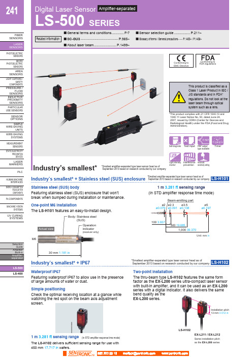
241LS-400FIBERSENSORSLASERSENSORSHUMAN MACHINEINTERFACESENERGY CONSUMPTIONVISUALIZATIONCOMPONENTSFA COMPONENTSMACHINE VISIONSYSTEMSUV CURINGSYSTEMSFeaturing stainless steel (SUS) enclosure that won’tbreak when bumped during installation or maintenance.(In STD amplifier response time mode)Unit: mm in Stainless steel (SUS) body 1 m 3.281 ft sensing rangeOne-point M6 installationFeaturing waterproof IP67 to allow use in the presenceof large amounts of water or dust.Two-point installationThe thru-beam type LS-H102 features the same formfactor as the EX-L200 series ultra-compact laser sensorwith built-in amplifier, and it can be used as an EX-L200series with a digital indicator. It also delivers the samebend quality as theEX-L200 series.The LS-H101 features an easy-to-install design.M6Body: Stainless steel(SUS)Operationindicator(receiver only)Actual size1 m 3.281 ft sensing range(In STD amplifier response time mode)The LS-H102 delivers sufficient sensing range for use with450 mm 17.717 in wafers.Check the optimal receiving location at a glance whilewatching the red spot on the beam axis adjustmentscreen.Simple positioningInstallation pitch13 mm 0.512 inEX-L211 / EX-L212LS-H102Same installation pitchas the EX-L200 series Waterproof IP67SEN TRONIC242LS-400FIBER SENSORS PHOTOELECTRIC SENSORS MICROPHOTOELECTRIC SENSORS AREASENSORS LIGHT CURTAINS /SAFETYCOMPONENTS PRESSURE / FLOWSENSORS INDUCTIVE PROXIMITY PLCHUMAN MACHINE INTERFACES ENERGY CONSUMPTION VISUALIZATION COMPONENTS FA COMPONENTS MACHINE VISION SYSTEMSUV CURING SYSTEMSIndustry’s smallest* + Thinnest profile* S mallest amplifier-separated type laser sensor head as of September 2013 based on research conducted by our companyLS-H201Coaxial designSmall, long-range spotEasy-to-see operation indicatorBy using a laser with high linearity in a coaxial design, the LS-H201 is able to deliver stable sensing in confined spaces as well as simple installation.The LS-H201 produces a spot with a diameter of 2 mm 0.079 in at a sensing range of up to 300 mm 11.811 in (in STD amplifier response time mode).The LS-H201’s operation indicator is visible from all directions.Featuring a 60% smaller design (by volume) than previous coaxial reflective models, our smallest unit is smaller in every dimension at just W8 × H23 × D18 mm W0.315 × H0.906 × D0.709 in (excluding indicators).0.315 in23mm ø2 mm ø0.079 in300 mm 11.811 inGasketLS-400FIBER SENSORS PHOTOELECTRICSENSORS MICROPHOTOELECTRICSENSORS AREA SENSORS LIGHT CURTAINS /SAFETY COMPONENTS PRESSURE /FLOW SENSORS INDUCTIVE PROXIMITY SENSORS PARTICULAR USE SENSORSSENSOR OPTIONS SIMPLE WIRE-SAVINGUNITS WIRE-SAVINGSYSTEMS MEASUREMENTSENSORS STATIC ELECTRICITYPREVENTION DEVICES LASER MARKERSPLCHUMAN MACHINEINTERFACES ENERGY CONSUMPTIONVISUALIZATION COMPONENTS FA COMPONENTS MACHINE VISIONSYSTEMS UV CURING SYSTEMSFX-500 series fiber sensor LS-500 series laser sensor0.315 in4 mm 0.157 inAmong industry’s fastest response times* 60 μs* A mplifier-separated type laser sensor amplifiers as ofSeptember 2013 based on research conducted by our company* S mallest amplifier-separated type laser sensor head as ofSeptember 2013 based on research conducted by our companyLS-501□Industry’s smallest* and thinnest designHorizontal symmetryFeaturing a simple system design process thanks to a light source that is placed in the center of the sensor head and a coaxial design.Engineered for maximum compatibility with fiber sensors in every aspect of its design, from form factor to operability, the LS-500 series delivers an environment that makes it easy to choose a laser sensor.The LS-H901 is even thinner than previous models, measuring just W8 × H23 (excluding indicators) × D18 mm W0.315 × H0.906 × D0.709 in .Maximum compatibility with fiber sensorsDetection of beam axis misalignmentDual outputs (self-diagnosis output)Stable sensing over the long term Logic operationsData bankThe LS-500 series features the same operation, menu displays, and form factor as the FX-500 series for increased compatibility with fiber sensors.The LS-500 series can detect any reduction in incident light intensity, for example due to the accumulation of dirt such as dust, and issue an alarm. Sensing output 2 can be set as self-diagnosis output. When you teach the threshold for sensing output 1, sensing output 2 is set accordingly, allowing you to shift the threshold by a previously set margin.The LS-500’s threshold-tracking function helpsmaintain stable sensing over the long term and reduce maintenance man-hours. The incident light intensity can be checked and the threshold automatically reset at a user-selected interval to track changes in light intensity due to environmental changes (such as dust, etc.) over extended periods of time. The LS-500’s ability to perform three logic operations (AND, OR, and XOR) on a standalone basis eliminates the need for a dedicated controller, cuts down onwiring, and lowers costs. This functionality can also be combined with the FX-500 series.Eight sets of amplifier settings can be stored in the unit’s built-in memory. The ability to save and load settings reduces workload when changing the setup in a multi-model production environment.LS-400PHOTO-ELECTRIC SENSORS MICRO PHOTO-ELECTRIC SENSORS AREA SENSORS LIGHT CURTAINS /SAFETY COMPONENTS PRESSURE / FLOW SENSORS INDUCTIVE PROXIMITY SENSORS PARTICULAR USE SENSORS SENSOR OPTIONS SIMPLE WIRE-SAVING UNITS WIRE-SAVING SYSTEMS MEASURE-MENT SENSORS STATIC ELECTRICITY PREVENTION DEVICES LASER MARKERS PLC HUMAN MACHINE INTERFACES ENERGY CONSUMPTION VISUALIZATION COMPONENTSFACOMPONENTS MACHINE VISION SYSTEMSUVCURING SYSTEMSORDER GUIDE056 222 38 18SEN TRONIC AG245Digital Laser Sensor LS-500SERIESLS-400FIBERSENSORSPHOTO-ELECTRICSENSORSMICROPHOTO-ELECTRICSENSORSAREASENSORSLIGHTCURTAINS /SAFETYCOMPONENTSPRESSURE /FLOWSENSORSINDUCTIVEPROXIMITYSENSORSPARTICULARUSESENSORSSENSOROPTIONSSIMPLEWIRE-SAVINGUNITSWIRE-SAVINGSYSTEMSMEASURE-MENTSENSORSSTATICELECTRICITYPREVENTIONDEVICESLASERMARKERSPLCHUMANMACHINEINTERFACESENERGYCONSUMPTIONVISUALIZATIONCOMPONENTSFACOMPONENTSMACHINEVISIONSYSTEMSUVCURINGSYSTEMSSensor head mounting bracketMaterial: Stainless steel (SUS304)Two M3 (length 14 mm 0.551 in)screws with washers [stainlesssteel (SUS304)] are attached.• MS-EXL2-5Fine-Rotatethrough360°Reflector• RF-310• RF-31Reflective tape9.2 mmAccessoriesMS-LS-1 (Sensor head mounting bracket)For LS-H201□ / LS-H901□mountingBack angledmountingRF-330 (Reflector)MS-EXL2-2 (Mounting plate for thru-beam type)Mounting plateMaterial: Stainless steel (SUS304)Two M2 (length 12 mm 0.472 in) screws with washers[stainless steel (SUS)] are attached.Material: Stainless steel (SUS)Material: Die-cast zinc alloyTwo M3 (length 14 mm 0.551 in) screws withwashers [stainless steel (SUS)], one M3 (length 10mm 0.394 in) hexagon-socket-head bolt [stainlesssteel (SUS)], and one M3 hexagon nut [stainlesssteel (SUS)] are attached.0.551 in) screws withwashers [stainless steel (SUS)] are attached.056 222 38 18*********************SEN TRONICAG246Digital Laser SensorLS-500SERIESLS-400FIBER SENSORS PHOTO-ELECTRIC SENSORS MICRO PHOTO-ELECTRIC SENSORS AREA SENSORS LIGHT CURTAINS /SAFETY COMPONENTS PRESSURE / FLOW SENSORS INDUCTIVE PROXIMITY SENSORS PARTICULAR USE SENSORS SENSOR OPTIONS SIMPLE WIRE-SAVING UNITSWIRE-SAVING SYSTEMS MEASURE-MENT SENSORS STATIC ELECTRICITY PREVENTION DEVICES LASER MARKERS PLC HUMAN MACHINE INTERFACES ENERGY CONSUMPTION VISUALIZATION COMPONENTS FACOMPONENTSMACHINE VISION SYSTEMS UVCURING SYSTEMSNotes: 1) Where measurement conditions have not been specified precisely, the conditions used were an ambient temperature of +23 °C +73.4 °F . 2) When using the thru-beam type LS-H101□ or LS-H102□, do not set the receiving light sensitivity (gctL) of the applicable LS-500 series amplifier to level2 or less. This is because there is a possibility of sensing becoming unstable.3) The sensing range of the coaxial reflective type sensor is specified for white non-glossy paper (100 × 100 mm 3.937 × 3.937 in ) as the object. 4) The sensing ranges for coaxial retroreflective type sensors are values for the RF-330 reflector. In addition, the sensing range is the possible settingrange for the reflector. The sensor can detect an object less than 0.01 m 0.033 ft away. Note that if there are white papers or specular objects near the sensor head, reflected light from these objects may be received. In such cases, use the amplifier unit’s receiving sensitivity function to lower thesensitivity, change the response time, or move the sensor head away from the target object. The incident light intensity may vary with the condition of the reflector surface. When using one of the applicable LS-500 series amplifiers, leave an adequate safety margin when setting the threshold.5) Make sure to confirm detection with an actual sensor before use. 6) This product complies with 21 CFR 1040.10 and 1040.11 Laser Notice No. 50, dated June 24, 2007, issued by CDRH (Center for Devices andRadiological Health) under the FDA (Food and Drug Administration). For details, refer to the Laser Notice No. 50.7) Cable cannot be extended.056 222 38 18*********************SEN TRONIC AG247Digital Laser Sensor LS-500SERIESLS-400FIBERSENSORSPHOTO-ELECTRICSENSORSMICROPHOTO-ELECTRICSENSORSAREASENSORSLIGHTCURTAINS /SAFETYCOMPONENTSPRESSURE /FLOWSENSORSINDUCTIVEPROXIMITYSENSORSPARTICULARUSESENSORSSENSOROPTIONSSIMPLEWIRE-SAVINGUNITSWIRE-SAVINGSYSTEMSMEASURE-MENTSENSORSSTATICELECTRICITYPREVENTIONDEVICESLASERMARKERSPLCHUMANMACHINEINTERFACESENERGYCONSUMPTIONVISUALIZATIONCOMPONENTSFACOMPONENTSMACHINEVISIONSYSTEMSUVCURINGSYSTEMS2) 25 mA if 5 or more amplifier are connected in cascade (excluding cable extension).3) Number of units that can be mounted close together: 0 for H-SP; 2 for FAST; 4 for STD, LONG, U-LG, or HYPR4) Select either sensing output 2 or external input as the connector type.056 222 38 18*********************SEN TRONICAG248Digital Laser SensorLS-500SERIESLS-400FIBER SENSORS PHOTO-ELECTRIC SENSORSMICRO PHOTO-ELECTRIC SENSORS AREA SENSORSLIGHTCURTAINS /SAFETY COMPONENTSPRESSURE /FLOW SENSORS INDUCTIVE PROXIMITY SENSORSPARTICULAR USE SENSORS SENSOR OPTIONS SIMPLE WIRE-SAVING UNITS WIRE-SAVING SYSTEMS MEASURE-MENT SENSORS STATIC ELECTRICITY PREVENTION DEVICES LASER MARKERS PLCHUMAN MACHINE INTERFACES ENERGY CONSUMPTION VISUALIZATION COMPONENTS FACOMPONENTSMACHINE VISION SYSTEMS UVCURING SYSTEMSSymbols ...D 1, D 2, D 3, D 4: Reverse supply polarity protection diodeZ D1, Z D2: Surge absorption zener diode Tr 1, Tr 2 : NPN output transistor%Notes: 1) The quick-connection sub cable does not have +V (brown) and 0 V (blue).The power is supplied from the connector of the main cable.2) Wiring when sensing output 2 is selected is shown with solid lines. Wiringwhen external input is selected is shown with broken lines.NPN output typeConnector typeCable typeI/O circuit diagramsNPN output typePNP output typeNotes: 1) The quick-connection sub cable does not have brown lead wire and blue leadwire. The power is supplied from the connector of the main cable.2) The quick-connection cable does not have gray or pink lead wires.Wiring diagramsTerminal layout of connector typeColor code of cable type / quick-connection cable Color code of cable type / quick-connection cable Notes: 1) The quick-connection sub cable does not have brown lead wire and blue leadwire. The power is supplied from the connector of the main cable.2) The quick-connection cable does not have gray or pink lead wires.* Connector for amplifier (CN-EP4) pin position%%Notes: 1) The quick-connection sub cable does not have +V (brown) and 0 V (blue).The power is supplied from the connector of the main cable.2) Wiring when sensing output 2 is selected is shown with solid lines. Wiringwhen external input is selected is shown with broken lines.%%%PNP output typeConnector typeCable typeSymbols ...D 1, D 2, D 3, D 4: Reverse supply polarity protection diodeZ D1, Z D2: Surge absorption zener diode Tr 1, Tr 2 : PNP output transistor056 222 38 18*********************SEN TRONIC AG249Digital Laser Sensor LS-500SERIESLS-400FIBERSENSORSPHOTO-ELECTRICSENSORSMICROPHOTO-ELECTRICSENSORSAREASENSORSLIGHTCURTAINS /SAFETYCOMPONENTSPRESSURE /FLOWSENSORSINDUCTIVEPROXIMITYSENSORSPARTICULARUSESENSORSSENSOROPTIONSSIMPLEWIRE-SAVINGUNITSWIRE-SAVINGSYSTEMSMEASURE-MENTSENSORSSTATICELECTRICITYPREVENTIONDEVICESLASERMARKERSPLCHUMANMACHINEINTERFACESENERGYCONSUMPTIONVISUALIZATIONCOMPONENTSFACOMPONENTSMACHINEVISIONSYSTEMSUVCURINGSYSTEMSMetal plateAccessory forMS-EXL2-1Cautions for laser beamsPart description (Amplifier)MountingAmplifierLS-H201□, LS-H901□<How to mount the amplifier>(1) F it the rear part of the mountingsection of the amplifier on a 35 mm1.378 in width DIN rail.(2) P ress down the rear part of themounting section of the unit on the 35 mm 1.378 in widthDIN rail and fit the front part of the mounting section tothe DIN rail.<How to mount the sensor head>(1) I nsert the sensor headconnector into the inlet until itclicks.(2) Fit the cover to the connector.<How to remove the amplifier>(1) Push the amplifier forward.(2) L ift up the front part of theamplifier to remove it.Note: B e careful. If the front part is lifted without pushing the amplifier forward,Sensor headLS-H101□• The tightening torqueshould be 0.98 N·m or less.LS-H102□• In case mounting this product,use a metal plate MS-EXL2-2(accessory).• The tightening torque should be0.5 N·m or less with M3 screws.<Not requiring the metal plate><Requiring the metal plate>• In case using the dedicated sensor head mountingbracket MS-EXL2-1 (optional) when mounting thisproduct, the metal plate MS-EXL2-2 (accessory) isrequired depending on the mounting direction. Mount asthe diagram below indicates.• The tightening torqueshould be 0.5 N·m orless.• When placing the sensorhead horizontally orvertically, the reflectormust also be positionedhorizontally or verticallyas shown in Fig. 1 below. I f the sensor head is placed horizontallyor vertically but the reflector is tilted as shown in Fig. 2 below, thereflection amount will decrease, which may cause unstable detection.Safety standards for laser beam products• A laser beam can harm human being’s eyes, skin, etc.,because of its high energy density. IEC has classifiedlaser products according to the degree of hazard and thestipulated safety requirements. LS-H□ is classified asClass 1 laser.Classification by IEC 60825-1width DIN railconnector(Purchase separately)Safe use of laser products• For the purpose of preventing users from sufferinginjuries by laser products, IEC 60825-1 (Safety of laserproducts). Kindly check the standards before use.(Refer to About laser beam.)* T his product complies with 21 CFR 1040.10 and 1040.11 Laser NoticeNo. 50, dated June 24, 2007, issued by CDRH (Center for Devices andRadiological Health) under the FDA (Food and Drug Administration).056 222 38 18*********************SEN TRONICAG250Digital Laser SensorLS-500SERIESLS-400FIBER SENSORS PHOTO-ELECTRIC SENSORS MICRO PHOTO-ELECTRIC SENSORS AREA SENSORS LIGHT CURTAINS /SAFETY COMPONENTS PRESSURE / FLOW SENSORS INDUCTIVE PROXIMITY SENSORS PARTICULAR USE SENSORS SENSOR OPTIONS SIMPLE WIRE-SAVING UNITS WIRE-SAVING SYSTEMS MEASURE-MENT SENSORS STATIC ELECTRICITY PREVENTION DEVICES LASER MARKERS PLC HUMAN MACHINE INTERFACESENERGY CONSUMPTION VISUALIZATION COMPONENTS FACOMPONENTSMACHINE VISION SYSTEMS UVCURING SYSTEMSFig. 1 Proper positioningWhen placing the sensor head horizontally or vertically, the reflector shall also be positioned horizontally or vertically.Fig. 2 Improper positioningWhen placing the reflector tilted even when the sensor head is positioned horizontally or vertically.Wiring• Make sure that the power supply is off while wiring.• Verify that the supply voltage variation is within the rating.• Take care that if a voltage exceeding the rated range is applied, or if an AC power supply is directly connected, the sensor may get burnt or damaged.• If power is supplied from a commercial switching regulator, ensure that the frame ground (F.G.) terminal of the power supply is connected to an actual ground.• Make sure to use the optional quick-connection cable for the connection of the amplifier [connector type LS-501(P )]. Extension up to total 100 m 328.084 ft is possible with 0.3 mm 2, or more, cable. However, in order to reduce noise, make the wiring as short as possible. Set the supply voltage after considering the voltage drop caused by the cable’s resistance.Others• Do not use during the initial transient time (0.5 sec. approx.) after the power supply is switched on.• B ecause the sensitivity is higher in U-LG and HYPER modes than in other modes, it can be more easily affected byextraneous noise. Check the operating environment before use.Amplifier LS-501 LS-501PAmplifierLS-501-C LS-501P-CCN-74-C1 CN-74-C2 CN-74-C5Main cable (Optional)Sub cable (Optional)CN-72-C1 CN-72-C2 CN-72-C5When adding units, wiring length must not exceed 50 m 164.042 ft (for 5 to 8 amplifiers) or 20 m 65.617 ft (for 9 to 16 amplifiers). <Correct><Incorrect>056 222 38 18*********************SEN TRONIC AG251Digital Laser Sensor LS-500SERIESLS-400FIBERSENSORSPHOTO-ELECTRICSENSORSMICROPHOTO-ELECTRICSENSORSAREASENSORSLIGHTCURTAINS /SAFETYCOMPONENTSPRESSURE /FLOWSENSORSINDUCTIVEPROXIMITYSENSORSPARTICULARUSESENSORSSENSOROPTIONSSIMPLEWIRE-SAVINGUNITSWIRE-SAVINGSYSTEMSMEASURE-MENTSENSORSSTATICELECTRICITYPREVENTIONDEVICESLASERMARKERSPLCHUMANMACHINEINTERFACESENERGYCONSUMPTIONVISUALIZATIONCOMPONENTSFACOMPONENTSMACHINEVISIONSYSTEMSUVCURINGSYSTEMSLS-H101□Sensor headNote: Not incorporated on the emitter.Sensor headLS-H102□Note: Not incorporated on the emitter.LS-H201□ LS-H901□Sensor head3.156.90.8MS-DIN-E End plate (Optional)Material: Acrylic (Reflector)ABS (Base)0.1650.217Reflector (Accessory for LS-H901□)RF-330Material: Acrylic (Reflector)ABS (Base)RF-310Reflector (Optional)Reflective tape (Optional)RF-33 RF-318.5Material: Cold rolled carbon steel (SPCC)(Uni-chrome plated)MS-DIN-2Amplifier mounting bracket (Optional) 056 222 38 18*********************SEN TRONICAG252Digital Laser SensorLS-500SERIESLS-400FIBER SENSORS PHOTO-ELECTRIC SENSORS MICRO PHOTO-ELECTRIC SENSORS AREA SENSORS LIGHT CURTAINS /SAFETY COMPONENTS PRESSURE / FLOW SENSORS INDUCTIVE PROXIMITY SENSORS PARTICULAR USE SENSORS SENSOR OPTIONS SIMPLE WIRE-SAVING UNITS WIRE-SAVING SYSTEMS MEASURE-MENT SENSORS STATIC ELECTRICITY PREVENTION DEVICES LASER MARKERSPLC HUMAN MACHINE INTERFACES ENERGY CONSUMPTIONVISUALIZATION COMPONENTSFACOMPONENTS MACHINE VISION SYSTEMS UVCURING SYSTEMSRear mounting bracketFoot angled mounting bracketUniversal sensor mounting bracketAssembly dimensionsMaterial: Stainless steel (SUS304)Two M3 (length 14 mm 0.551 in ) screws with washers [stainless steel (SUS304)] are attached.Material: Stainless steel (SUS304)Note: Without using the mounting plate,beam misalignment may occur.Mounting drawing with the emitter of LS-H102□Assembly dimensionsMounting drawing with the receiver of LS-H102□Note: Screws are not attached. Purchase separately.0.0590.0390.10233-M3 × 0.5 14 Note: This is the adjustable range of the movable part.Mounting drawing with the receiver of LS-H102□112 8 R13 t 1.5 MS-LS-1Sensor head mounting bracket (Accessory for LS-H201□, LS-H901□)Sensor head mounting bracket for LS-H102□ (Optional)MS-EXL2-1MS-EXL2-2Mounting plate (Accessory for LS-H102□)Sensor head mounting bracket for LS-H102□ (Optional)MS-EXL2-4Sensor head mounting bracket for LS-H102□ (Optional)MS-EXL2-5Material: Stainless steel (SUS304)Two M3 (length 14 mm 0.551 in ) screws with washers [stainless steel (SUS304)] are attached.Material: Die-cast zinc alloyTwo M3 (length 14 mm 0.551 in ) screws with washers, one M3 (length 10 mm 0.394 in ) hexagon socket-head bolt [stainless steel (SUS)], and one M3 hexagon nut [stainless steel (SUS)] are attached.056 222 38 18*********************SEN TRONIC AG。
EE-SF5中文资料(omron)中文数据手册「EasyDatasheet - 矽搜」

Sensing object: White paper
(μA)
with a reflection factor of 90%
L
光电流I
间距d(毫米) 感应角度特性 (典型值)
(%)
L
相对光电流I
Ta = 25°C I F = 20 mA V CE = 10 V
Sensing object: W hite paper with a reflec tion fac tor of 90%
IF = 40 mA IF = 30 mA
光电流I
IF = 20 mA IF = 10 mA
集电极 - 发射极
响应时间与负载 阻力特性 (典型值)
电压V CE (V)
VCC = 5 V Ta = 25°C
响应时间TR,TF(微秒)
周围温度Ta(℃)
检测距离特点 (典型值)
Ta = 25°C VCE = 10 V
微型光电传感器(反射)
EE-SF5(-B)与集电极 耗散温度额定值
(mA)
F
正向电流I
光电流与正向电流 特性(典型)
(mW) (μA)
C L
Ta = 25°C VCE = 10 V d = 5 mm Sensing object: White paper with a reflection factor of 90%
d1
相对光电流I
d1 = 5 mm
距离d 感应角度特性 (典型值)
(%)
L
2 (毫米)
距离d
响应时间测量 电路
2 (毫米)
Input
90 %
Output
10 %
相对光电流I
Sensing object
欧姆龙S10系列光电传感器使用说明书

S10 SERIESINSTRUCTION MANUALCONTROLSOUTPUT LED (S10-…A01/B01/C01/C11/C21/D01/F01/T01)The yellow LED indicates the output status.STABILITY LED (S10-…A01/B01/C01/C11/C21/D01/F01)green LED ON indicates that the received signal has a safety margin greater than 30% compared to the output switching value.POWER ON LED (S10- (00)The green LED indicates that the sensor is operating.TRIMMER (S10-…A01/B01/C01/C11/C21/D01/F01/T01)The trimmer can be used to adjust sensitivity; the operating distance increases turning the trimmer clockwise.WARNING: The trimmer rotation is limited to 270° by a mechanical stop. Do not apply excessive torque when adjusting (max 40 Nmm).CONNECTIONSNPN OUTPUT PNP OUTPUTS10-…G00-XE S10-…G00-XFM12 CONNECTOR14Power supply: 10 … 30 VDc limit valuesRipple: 2 Vpp max.Current consumption(output current excluded):30 mA max.Outputs: NPN or PNP; 30 Vdc max. (short-circuit protection at 200 mA)Output current: 150 mA max.Output saturation voltage: 1 V max.Response time:1 ms max.2 ms max. mod. F01/G00Switching frequency:500 Hz max.250 Hz max. mod. F01/G00Indicators:OUTPUT LED (YELLOW) G00 mod. excludedSTABILITY LED (GREEN) A01/B01/C01/C11/C21/D01/F01 mod.POWER ON LED (GREEN) G00 mod.Setting: sensitivitytrimmer (G00 mod. excluded)Selection Dark/Light: selection light (L) selection dark (D)..Operating temperature: -25 … 55 °CStorage temperature: -25 … 70 °CDielectric strength: 500 Vac 1 min., between electronics and housingInsulating resistance: >20 MΩ 500 Vdc, between electronics and housingOperating distance (minimumvalues):A01: 0.1…4 m on R2 / B01: 0.1…3 m on R2 / T01: 0.1…0.8 m on R2C01: 1…10 cm / C11: 1…35 cm / C21: 1…60 cmD01: 14 mm with 1.5 mm spotF01/G00: 0…18 mEmission type:infrared (880 nm) mod.A01/C01/C11/C21/G00red (660 nm) mod.B01/D01/T01Ambient light rejection: according to EN 60947-5-2Vibrations: 0.5 mm amplitude, 10 … 55 Hz frequency, for every axis (EN60068-2-6)Shock resistance: 11 ms (30 G) 6 shock for every axis (EN60068-2-27)Housing/connector material: Nichel-plated brass (S10-MA vers.) / AISI 316L stainless steel (S10-NA vers.)Lens material: PMMA plasticMechanical protection: IP69KConnections: metal M12 4-pole connectorWeight: 50 g. max.SETTINGThe following procedures are valid for the LIGHT mode. The yellowOutput LED (OUT) works in the opposite manner in the DARK modemodels.Alignment S10-…A01/B01Position the sensor and reflector on opposite sides.Turn the sensitivity trimmer to maximum. Find the points where theyellow LED (OUT) is switched ON and OFF in both vertical andhorizontal positions and fix the sensor in the centre between thesepoints.Optimum operation is obtained when both LEDs are switched ON.If necessary, reduce sensitivity in order to detect very small targets.In order to improve alignment, repeat the procedure detailed abovewhilst progressively reducing the sensitivity.Alignment S10-…T01Position the sensor and reflector on opposite sides.Turn the sensitivity trimmer to maximum. Find the points where theyellow LED (OUT) is switched ON and OFF in both vertical andhorizontal positions and fix the sensor in the centre between thesepoints.If necessary, reduce sensitivity in order to detect transparent objects. Inorder to improve alignment, repeat the procedure detailed above whilstprogressively reducing the sensitivity.Alignment S10-…F01/G00Turn the sensitivity trimmer to maximum. Find the points where theyellow LED (OUT) is switched ON and OFF in both vertical andhorizontal positions and fix the sensor in the centre between thesepoints. Optimum operation is obtained when both LEDs are switchedON.If necessary, reduce sensitivity using the trimmer, in order to detect verysmall targets. In order to improve alignment, repeat the proceduredetailed above whilst progressively reducing the sensitivity.Alignment S10-…C01/C11/C21/D01The green LED is ON and the yellow LED is OFF.Place the target opposite the sensor. Turn thesensitivity trimmer clockwise until the yellow LEDturns ON (Target detected state, pos.A).clockwise until the yellow LED turns ON (Background detected state,pos.B).The trimmer reaches maximum if the background is not detected.Turn the trimmer to the intermediate position C, between the twopositions A and B. The green LED must be ON.TEST FUNCTION (S10- (00)The TEST input can be used to inhibit the emitter and verify that thesystem is correctly operating.The receiver output should switch when the test is activated while thebeam is uninterrupted.The inputs activating voltage range is 10 … 30 Vdc, whilst respecting thepolarity.DECLARATION OF CONFORMITYWe DATASENSOR S.p.A. declare under our sole responsibility thatthese products are conform to the 2004/108/CE, 2006/95/CE Directivesand successive amendments.WARRANTYDATASENSOR S.p.A. warrants its products to be free from defects.DATASENSOR S.p.A. will repair or replace, free of charge, any productfound to be defective during the warranty period of 36 months from themanufacturing date.This warranty does not cover damage or liability deriving from theimproper application of DATASENSOR products.DATASENSOR S.p.A. Via Lavino 26540050 Monte S. Pietro - Bologna - ItalyTel: +39 051 6765611 Fax: +39 051 6759324DATASENSOR S.p.A. cares for the environment: 100% recycledpaper.DATASENSOR S.p.A. reserves the right to make modificationsand improvements without prior notification.826003170 Rev.A。
OMRON光电传感器操作手册
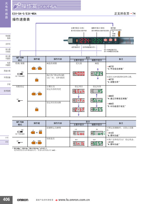
䗝ᢽᖂߚ䖍㓬 ऩջ䖍㓬˖ǃϸջ䖍㓬˖ 䗝ᢽᖂߚࡼᯊ ᖂߚડᑨᯊ䯈 ऩջ䖍㓬ĂõV˖ǃµV˖ǃPV˖ǃPV˖ǃPV˖ ϸջ䖍㓬ĂõV˖ǃµV˖ǃPV˖ǃPV˖ǃPV˖ $7&䫭䇃䕧ߎ˖ ҙ$7&ൟ ᣝ䗮䘧䕧ߎ˖ǃ ফܝㄝ㑻Ͼ䯜ؐП䯈ᯊ䕧ߎ˖ 㞾䆞ᮁ䕧ߎ˖ $7&ࡳ㛑᳝ᬜ˖ǃ $7&ࡳ㛑᮴ᬜ˖ ᮴䆒ᅮ˖ǃ$7&ⱘᓔྟ໘⧚˖ǃ ࡳ⥛䇗䇤ˇ$7&ⱘᓔྟ໘⧚˖
581
䆒ᅮ㒧ᴳৢˈ䖨ಲࠄ ᪡ࠡⱘᰒ冫
581
㟇581
㟇581
408
᳔ᮄѻક䌘᭭䇋ⱏᔩ
᪡㆛⬉ܝӴᛳ఼
ܝ ⬉ Ӵ ᛳ ఼
䆒ᅮࡳ㛑 6(7ᓣ
䗮⫼gᷛ䆚Ẕ⌟ൟ
(;'$ƶ6
ࡳ㛑ߛᤶᯊ᠔ᰒ冫ⱘݙᆍЎߎॖᯊⱘ䆒㕂DŽ ḍ䆒ᅮⱘݙᆍˈࡳ㛑ߛᤶЁৃ㛑Ӯࡴᮄⱘ乍ⳂDŽ
℆581⢊ᗕϟߛᤶᓣᯊ
ঠ䕧ߎ
℆ߛᤶϾ䗮䘧ⱘ䕧ߎݙᆍᯊ
⫼䗨ߚ㉏ ೈ䆒 ҟ㒡 ᡔᴃᣛफ
℆ߛᤶ$7&ࡳ㛑᳝ᬜ᮴ᬜᯊ
ҙ$7&ൟ 䆒ᅮᅠ៤ৢ
ᇚ6(7581ߛᤶᓔ݇䆒Ў 581 DŽ
581
ࡳ㛑ϔ㾜 াࣙᣀҢ䗮⫼ൟᓔྟᮄⱘࡳ㛑DŽᴀࡳ㛑䚼ߚ䇋খ䯙䗮⫼ൟDŽ
83 '2:1
䗮䖛Āߛᤶᰒ冫āࡳ㛑ᬍᰒ冫ᮍ⊩ᯊˈ䗮䖛䬂᪡ᇚ䕙ࡽ᭄ᄫᰒ冫 ߛᤶЎ䯜ؐDŽ
ᡔᴃ㆛ ᪡㆛
䆶⬉䆱800-820-4535
407
ܝ ⬉ Ӵ ᛳ ఼
᪡㆛⬉ܝӴᛳ఼
䗮䖛冫ᬭ䆒ᅮ䯜ؐ 6(7ᓣ
冫ᬭⱘᮍ⊩ˈ᳝བϟಯ辵DŽՓ⫼ᯊ䇋䗝ᢽ᳔ড়䗖ⱘᮍ⊩DŽ 581ᓣϟг㛑䖯㸠冫ᬭ ҙᎹӊ᳝᮴冫ᬭǃ㞾ࡼ冫ᬭ DŽ ᪡ᮍ⊩䇋খ䯙ѻક䰘ᏺⱘĀՓ⫼䇈ᯢкāDŽ ᔧ䕙ࡽ᭄ᄫᰒ冫ߎ⦄Ā29(5āǃĀ/2āǃĀ1($5āᯊˈ㸼冫ߎ䫭DŽ 䇋䞡ᮄ䇗㡖ᑊ䆒ᅮDŽ
欧姆龙(OMRON)SSC-T801-835型号光幕传感器 说明书
Light CurtainSensorsNew type with radial crossray methodSmall objects and flat tape-like objects detectedConvenient simplified wiring requiring no clock(synchronization) lineCompact and flat (14.5 mm)Water resistance to IP 67TypeRadial Cross Ray Method276277Light Curtain SensorsSSC-T800Applicable power supply unitPS SeriesHigh capacity of 200 mA at 12(General-purpose type)PS3NPS3N-SR(Multifunctional type)PS3FPS3F-SRRating/Performance/SpecificationEnvironmental Specification78Light Curtain Sensors SSC-T800Input/Output Circuit and Connection12 24V12 24VTransmitter ReceiverThe output transistor turns off when load short circuits oroverload occurs. Check the load and turn the powerback onSettingInstall the transmitter and receiver face-to-face.Swivel the transmitter and receiver vertically and horizontally to install them at the center of the area in which the operation indicator (orange LED) is illuminated for the individual direction.The tightening torque for installing the sensor (with M4 screws) should be up to 0.6 N m.Displacement in the A direction may be up to ±30mm.Displacement in the B direction should be within ±10mm.If the transmitter and receiver are too closely installed to eachother or light axes are misaligned, the output may beunstable. When the light axes are aligned, the operationreturns to normal.Any reflecting object (wall, floor, machine, etc.) within theeffective range between the transmitter and receiver mayallow the light of the sensor to go around the detection object,which is supposed to block the light, and reach the receiver.Choose the installation location carefully.Any glossy object such as a coated surface in thesurrounding area must be at least 100mm away for thedistance setting of within 1m and 150mm away for thedistance setting of over 1m.Use caution with interference when installing sensoradjacently.Reflecting object278279Light Curtain SensorsD e t e c t i n g d i s t a n c e (m m )Position (mm)0D e t e c t i n g d i s t a n c e(m )Position (mm)21015015010010050500D e t e c t i n g d i s t a n c e(m )Position (mm)Position (mm)D e t e ct i n g d i s t a n c e (m )Position (mm)Vertical effective rangeSSC-T800Characteristics (T ypical Example)Parallel displacement characteristicsSSC-T801D e t e c t i n g d i s t a n c e (m )Position (mm)SSC-T802210D e t e c t i n g d i s t a n c e (m )Position (mm)SSC-T804SSC-T805SSC-T850SSC-T810SSC-T815SSC-T830SSC-T835Light Curtain Sensors SSC-T80050040030020010015201520101055Detectingdistance(mm)Angle(degrees)15201520101055Detectingdistance(m)Angle (degrees)1Detectingdistance(m)Angle (degrees)1.50.515201520101055Detectingdistance(m)Angle (degrees)Detectingdistance(m)Angle (degrees)Transmitter ReceiverCharacteristics (T ypical Example)Operating angle characteristicsSSC-T801Detectingdistance(m)Angle (degrees)SSC-T802Detectingdistance(m)Angle (degrees)SSC-T804 SSC-T805SSC-T850SSC-T810SSC-T815SSC-T830SSC-T835280281Light Curtain Sensors0S m a l l e s t d e t e c t a b l e o b j e c t d i a m e t e r (m m )Detecting distance (mm)151050S m a l l e s t d e t e c t a b l e o b j e c t d i a m e t e r (m m )Detecting distance (mm)10155S m a l l e s t d e t e c t a b l e o b j e c t d i a m e t e r (m m )Detecting distance (mm)510S m a l l e s t d e t e c t a b l e o b j e c t d i a m e t e r (m m )Detecting distance (mm)10200Sm a l l e s t d e t e c t a b l e o b j e c t d i a m e t e r (m m )Detecting distance (m)10200S m a l l e s t d e t e c t a b l e o b j e c t d i a m e t e r (m m )Detecting distance (mm)5100S m a l l e s t d e t e c t a b l e o b j e c t d i a m e t e r (m m )Detecting distance (m)SSC-T800Characteristics (T ypical Example)Smallest detectable object diameter characteristicsSSC-T8010S m a l l e s t d e t e c t a b l e o b j e c t d i a m e t e r (m m )Detecting distance (m)SSC-T802151050S m a l l e s t d e t e c t a b l e o b j e c t d i a m e t e r (m m )Detecting distance (m)SSC-T805SSC-T850SSC-T815SSC-T835Light Curtain SensorsDimensions (in mm) SSC-T800282283Light CurtainSensors。
Omron QM Series 光电传感器说明书
Photoelectric Sensors tSEN-69
1-800-633-0405
For the latest prices, please check .
QM Series Photoelectric Sensors
$44.50
NPN
2m [6.5 ft] cable
Diagram 1
$44.50 $44.50
0–1m [0 – 3.28 ft]
Visible Red
NPN
630nm
PNP
4-pin M8 quick-disconnect 2m [6.5 ft] cable
Diagram 1 Diagram 2
Note: Purchase reflectors separately.
Emission Type
Visible Red 630nm
Infrared 850nm
Logic NPN NPN PNP PNP NPN NPN PNP PNP NPN NPN PNP PNP
Connection 2m [6.5 ft] cable 4-pin M8 quick-disconnect 2m [6.5 ft] cable 4-pin M8 quick-disconnect 2m [6.5 ft] cable 4-pin M8 quick-disconnect 2m [6.5 ft] cable 4-pin M8 quick-disconnect 2m [6.5 ft] cable 4-pin M8 quick-disconnect 2m [6.5 ft] cable 4-pin M8 quick-disconnect
1-800-633-0405
For the latest prices, please check .
OMRON Q45VR3系列光电感应器说明书
Q45VR3 Seriespage 2Banner Engineering Corp. • Minneapolis, • Tel: 763.544.3164*9 m (30')cables are available by adding suffix “W/30” to the model number of any cabled sensor (e.g., Q45VR3LV W/30)A model with a QD connector requires a mating cable; see page 10.ModelsRangeCable*SupplyVoltageOutput TypeExcess GainBeam PatternNon-Polarized1101001000.10 m .33 ft1.0 m 3.3 ft10 m 33 ft.01 m .033 ftE X C E S S G A I NDISTANCE Q45LVRetroreflective ModeWith BRT-3 Reflector12 m 40 ft15 m 50 ft9 m 30 ft6 m 20 ft3 m 10 ft025 mm 50 mm75 mm25 mm50 mm 75 mm 01.0 in 2.0 in 3.0 in1.0 in2.0 in3.0 in DISTANCEQ45LVRetroreflective ModeWith BRT-3 Reflector Polarized1101001000.10 m .33 ft 1.0 m 3.3 ft 10 m 33 ft.01 m .033 ftE X C E S S G A I NDISTANCE Q45LPRetroreflective Mode With BRT-3 Reflector6 m 20 ft 7.5 m 25 ft4.5 m 15 ft 3 m 10 ft 1.5 m 5 ft 025 mm 50 mm 75 mm25 mm50 mm 75 mm 01.0 in 2.0 in 3.0 in1.0 in2.0 in3.0 in DISTANCEQ45LPRetroreflectiveModeWith BRT-3 Reflector Q45VR3LPQ45VR3LPQ0.15 to 6 m (6" to 20')Q45VR3LVQ45VR3LVQ5-wire 2 m (6.5')5-PinMini-style QDUniversal 12 - 250V dc or24 - 250V ac SPDT Electro-mechanical Relay0.08 to 9 m (3" to 30')5-wire 2 m (6.5')5-PinMini-style QDUniversal 12 - 250V dc or24 - 250V ac SPDT Electro-mechanical RelayQ45VR3 Series Retroreflective-Mode ModelsThe visible red sensing beam of these sensors makes them very easy to align.Model Q45VR3LP polarizes the emitted light and filters out unwanted reflections,making sensing possible in applications otherwise considered unsuited toretroreflective sensing performance. Specified using the model BRT-33" reflector (see the Accessories section of your current Banner Photoelectric Sensors catalog for further information).Visible red, 680 nmNon-Polarized PolarizedPQ45VR3 Seriespage 3Banner Engineering Corp. • Minneapolis, • Tel: 763.544.3164Q45VR3 Series Diffuse-Mode Models500 mm 20.0 in400 mm 16.0 in 300 mm 12.0 in 200mm 8.0 in 100 mm 4.0 in 005 mm10 mm 15 mm5 mm10 mm 15 mm 00.2 in 0.4 in 0.6 in0.2 in 0.4 in 0.6 inDISTANCEQ45DDiffuse ModeModelsRangeCable*Supply VoltageOutput TypeExcess GainBeam PatternShort RangeQ45VR3DLQ45VR3DLQ1. 8 m(6')5-wire 2 m (6.5')5-PinMini-style QDUniversal 12 - 250V dc or24 - 250V ac 11010010 mm 0.4 in 100 mm 4.0 in 1000 mm 40 in1.0 mm 0.04 in1000E X C E S S G A I NDISTANCEQ45DDiffuse Mode2.4 m 8 ft3.0 m 10 ft1.8 m 6 ft1.2 m 4 ft0.6 m 2 ft25 mm 50 mm 75 mm25 mm50 mm 75 mm01.0 in 2.0 in 3.0 in1.0 in2.0 in3.0 in DISTANCEQ45DLDiffuse ModeLong RangeQ45VR3DXQ45VR3DXQ3 m (10')5-wire 2 m (6.5')5-PinMini-style QD1101001000.10 m .33 ft 1.0 m 3.3 ft 10 m 33 ft.01 m .033 ftE X C E S S G A I NDISTANCEQ45DLDiffuse ModeQ45VR3DQ45VR3DQ45 cm (18")5-wire 2 m (6.5')5-PinMini-style QDUniversal 12 - 250V dc or24 - 250V ac SPDT Electro-mechanical RelayPerformance based on 90% reflectance white test cardSPDT Electro-mechanical RelayUniversal 12 - 250V dc or24 - 250V ac 3.0 m 10 ft2.4 m 8 ft 1.8 m 6 ft 1.2 m 4 ft 0.6 m 2 ft 025 mm 50 mm 75 mm25 mm50 mm 75 mm 01.0 in 2.0 in 3.0 in1.0 in2.0 in3.0 in DISTANCEDiffuse ModeQ45DXHigh Power1101000.1 m 0.33 ft 1.0 m 3.3 ft 10 m 33 ft0.01 m 0.033 ft1000E X C E S S G A I NDISTANCEQ45DXDiffuse ModeSPDT Electro-mechanical RelayInfrared, 880 nmThese diffuse-mode models detect objects by sensing the reflection of their own emitted light.Ideal for use when the reflectivity and profile of the object to be sensed are sufficient to return a large percentage of emitted light back to the sensor. Model Q45VR3DX is the first choice for dif-fuse-mode applications when there are no background objects to falsely return light.Q45VR3 Seriespage 4Banner Engineering Corp. • Minneapolis, U.S.A. • Tel: 763.544.3164*9 m (30')cables are available by adding suffix “W/30” to the model number of any cabled sensor (e.g., Q45VR3CV W/30)A model with a QD connector requires a mating cable; see page 10.Visible red, 680 nmThese sensors are ideal for reflective sensing of very small parts or profiles, and can accurately sense the position of parts approaching from the side. Will ignore all but highly reflective objects that are outside the sensing range.Q45VR3 Series Convergent-Mode Models190 mm 7.5 in150 mm 6.0 in 113 mm 4.5 in 75 mm 3.0 in 38 mm 1.5 in 01.2 mm2.5 mm3.8 mm1.2 mm2.5 mm3.8 mm 00.05 in 0.10 in 0.15 in0.05 in 0.10 in 0.15 in DISTANCEQ45CVConvergent ModeModelsFocusCable*Supply VoltageOutput TypeExcess Gain Beam PatternQ45VR3CVQ45VR3CVQ38 mm (1.5")Spot Size at Focus:1.3 mm (0.05")5-wire 2 m (6.5')5-PinMini-style QDUniversal 12 - 250V dc or24 - 250V ac SPDT Electro-mechanical Relay11010010 mm .4 in 100 mm 4 in 1000 mm 40 in1 mm .04 in1000E X C E S S G A I NDISTANCEQ45CVConvergent Mode190 mm 7.5 in150 mm 6.0 in 113 mm 4.5 in 75 mm 3.0 in 38 mm 1.5 in 01.2 mm2.5 mm3.8 mm1.2 mm2.5 mm3.8 mm 00.05 in 0.10 in 0.15 in0.05 in 0.10 in 0.15 in DISTANCEQ45CV4Convergent ModeQ45VR3CV4Q45VR3CV4Q100 mm(4")Spot Size at Focus:1.5 mm (0.06")5-wire 2 m (6.5')5-PinMini-style QDUniversal 12 - 250V dc or24 - 250V ac SPDT Electro-mechanical Relay11010010 mm .4 in 100 mm 4 in 1000 mm 40 in1 mm .04 in1000E X C E S S G A I NDISTANCEQ45CV4Convergent ModePerformance based on 90% reflectance white test card11010010 mm 0.4 in100 mm 4 in1000 mm 40 in1.0 mm 0.04 in1000EX C E S S G A I NDISTANCEQ45FVOpposed ModeIT23S fibersIT13S fibers300 mm 12 in250 mm 10 in 200 mm 8 in 150 mm 6 in 100 mm 4 in 0010 mm 20 mm 30 mm10 mm20 mm 30 mm00.4 in 0.8 in 1.2 in0.4 in 0.8 in 1.2 in DISTANCEQ45FVOpposed ModeIT23S FibersIT13S Fibers2.0 m 75 in1.6 m 60 in 1.2 m 45 in0.8 m 30 in0.4 m 15 in050 mm 100 mm 150 mm50 mm100 mm 150 mm02.0 in 4.0 in 6.0 in2.0 in 4.0 in 6.0 in DISTANCEQ45FOpposed ModeIT23S FibersIT13S FibersBP Q45F opp.eps page 5Q45VR3 SeriesThese models are an excellent choice for glass fiber optic applications where faster sensor response is not important. Their high excess gain means thatopposed individual fibers can operate reliably in many very hostile environments.Also, special miniature bifurcated fiber optic assemblies with bundle sizes as small as 0.5 mm (.020") dia. may be used successfully for diffuse-mode sensing when using sensor model Q45VR3F(Q). For more information on compatible glass fiber optics, refer to your current Banner Photoelectric Sensors catalog.Q45VR3 Series Glass Fiber-Optic ModelsModelsRangeCable*Supply VoltageOutput TypeExcess Gain Beam PatternInfrared, 880 nm1101000.1 m 0.33 ft 1.0 m 3.3 ft 10 m 33 ft0.01 m 0.03 ft1000E X C E S S G A I NDISTANCEQ45FOpposed ModeIT23S fibersIT13S fibersDiffuse mode performance based on 90% reflectance white test cardQ45VR3FQ45VR3FQRange varies by sensing mode and fiber optics used5-wire 2 m (6.5')5-PinMini-style QDUniversal 12 - 250V dc or24 - 250V ac SPDT Electro-mechanical RelayInfrared, 880 nm and Visible Red, 650 nmQ45VR3FVQ45VR3FVQRange varies by sensing mode and fiber optics used5-wire 2 m (6.5')5-PinMini-style QDUniversal 12 - 250V dc or24 - 250V ac SPDT Electro-mechanical RelayVisible Red, 650 nm11010010 mm 0.4 in 100 mm 4.0 in 1000 mm 40 in1 mm 0.04 in1000E X C E S S G A I NDISTANCEQ45FDiffuse ModeBT23S FiberBT13S Fiber125 mm 5 in100 mm 4 in 75 mm 3 in 50 mm 2 in25 mm 1 in1.3 mm2.5 mm3.8 mm1.3 mm2.5 mm3.8 mm 00.05 in 0.10 in 0.15 in0.05 in0.10 in0.15 in DISTANCEQ45F Diffuse ModeBT23S FiberBT13S Fiber11010010 mm 0.4 in100 mm 4.0 in1000 mm 40 in1 mm 0.04 in1000EX C E S S G A I NDISTANCEQ45FVDiffuse ModeBT23S FiberBT13S Fiber 25 mm 1.0 in20 mm 0.8 in 15 mm 0.6 in10 mm 0.4 in5 mm 0.2 in1.0 mm2.0 mm3.0 mm1.0 mm2.0 mm3.0 mm 00.04 in 0.08 in 0.12 in0.04 in 0.08 in 0.12 in DISTANCEQ45FVDiffuse ModeBT23S Fiber BT13S FiberBanner Engineering Corp. • Minneapolis, • Tel: 763.544.3164Q45VR3 Seriespage 6Banner Engineering Corp. • Minneapolis, • Tel: 763.544.3164*9 m (30')cables are available by adding suffix “W/30” to the model number of any cabled sensor (e.g., Q45VR3FP W/30)A model with a QD connector requires a mating cable; see page 10.Visible red, 660 nmLower in cost than glass fiber optics, plastic fiber optics are ideal for use in situ-ations where environmental conditions allow (for example, low levels of acids,alkalis, and solvents). Most are easily cut to length in the field, and are available in a variety of sensing end styles. For more information on compatible plastic fiber optics, refer to your current Banner Photoelectric Sensors catalog.Q45VR3 Series Plastic Fiber-Optic ModelsModelsRangeCable*Supply VoltageOutput TypeExcess GainBeam PatternQ45VR3FPQ45VR3FPQ11010010 mm0.4 in 100 mm 4.0 in 1000 mm 40 in1 mm 0.04 in1000E X C E S S G A I NDISTANCEQ45FPOpposed ModePIT46U FibersPIT26U Fibers125 mm 5.0 in100 mm 4.0 in 75 mm 3.0 in 50 mm 2.0 in 25 mm 1.0 in15 mm 30 mm 45 mm15 mm30 mm 45 mm00.6 in 1.2 in 1.8 in0.6 in1.2 in 1.8 in DISTANCEQ45FPOpposed ModePIT46U FibersPIT26U FibersDiffuse mode performance based on 90% reflectance white test cardRange varies by sensing mode and fiber optics used5-wire 2 m (6.5')5-PinMini-style QDUniversal 12 - 250V dc or24 - 250V ac SPDT Electro-mechanical Relay1101001 mm 0.04 in10 mm 0.4 in100 mm 4 in0.1 mm 0.004 in1000E X C E S S G A I NQ45FPDiffuse ModePBT46U FiberPBT26U Fiber50 mm 2.0 in40 mm 1.6 in 30 mm 1.2 in 20 mm 0.8 in 10 mm 0.4 in 006 mm12 mm 18 mm6 mm12 mm 18 mm00.25 in 0.50 in 0.75 in0.25 in 0.50 in 0.75 in DISTANCEQ45FPDiffuse ModePBT46U FiberBanner Engineering Corp. warrants its products to be free from defects in material and workmanship for one year following the date of shipment. Banner Engineering Corp. will repair or replace, free of charge, any product of its manufacture which, at the time it is returned to the factory, is found to have been defective during the warranty period.This warranty does not cover damage or liability for misuse, abuse, or the improper application or installation of the Banner product.THIS LIMITED WARRANTY IS EXCLUSIVE AND IN LIEU OF ALL OTHER WARRANTIES WHETHER EXPRESS OR IMPLIED (INCLUDING, WITHOUT LIMITATION, ANY WARRANTY OF MERCHANTABILITY OR FITNESS FOR A PARTICULAR PURPOSE), AND WHETHER ARISING UNDER COURSE OF PERFORMANCE, COURSE OF DEAL-ING OR TRADE USAGE.This Warranty is exclusive and limited to repair or, at the discretion of Banner Engineering Corp., replacement. IN NO EVENT SHALL BANNER ENGINEERING CORP. BE LIABLE TO BUYER OR ANY OTHER PERSON OR ENTITY FOR ANY EXTRA COSTS, EXPENSES, LOSSES, LOSS OF PROFITS, OR ANY INCIDENTAL, CONSEQUENTIAL OR SPECIAL DAMAGES RESULTING FROM ANY PRODUCT DEFECT OR FROM THE USE OR INABILITY TO USE THE PRODUCT, WHETHER ARISING IN CONTRACT OR WARRANTY, STATUTE, TORT, STRICT LIABILITY, NEGLIGENCE, OR OTHERWISE.Banner Engineering Corp. reserves the right to change, modify or improve the design of the product without assuming any obligations or liabilities relating to any product previously manufactured by Banner Engineering Corp.。
Omron E3F1光电传感器说明书
1•M18 size Photoelectric sensor with best value at competitive price •Bright visible red LED enabling easy alignment•Compact and robust housing for easy integration into machines •Reliable operation in all industrial environmentsOrdering InformationSensors [Refer to Dimensions on page 5.]Reflectors [Refer to Dimensions on page 6.]Reflectors required for Retro-reflective Sensors: A Reflector is not provided with the Sensor. Be sure to order a Reflector separately.Mounting brackets [Refer to Dimensions on page 6.]A Mounting Bracket is not enclosed with the Sensor. Order a Mounting Bracket separately if required.*2The Reflector is sold separately.Red lightSensorSensing distanceAppearanceModelQuantityRemarksE 3F1-R @0.1 to 3 m E39-R1S 1for E 3F1-R @E3F12Sensor I/O connectorsModels for Connectors: A Connector is not provided with the Sensor. Be sure to order a Connector separately. SpecificationsSensor Size Cable Appearance Cable type ModelM12 connector types M12S tandard2 m4-wireXS2F-M12PVC4S2M-EU5 m XS2F-M12PVC4S5M-EU2 m XS2F-M12PVC4A2M-EU5 m XS2F-M12PVC4A5M-EUSensing method Through-beam Retro-reflective Diffuse-reflective Model NPNoutputPre-wired E3F1-TN11 2M E3F1-RN11 2M E3F1-DN11 2M E3F1-DN12 2MM12 Connector E3F1-TN21E3F1-RN21E3F1-DN21E3F1-DN22 PNPoutputPre-wired E3F1-TP11 2M E3F1-RP11 2M E3F1-DP11 2M E3F1-DP12 2MItem M12 Connector E3F1-TP21E3F1-RP21E3F1-DP21E3F1-DP22Sensing distance15 m0.1 to 3 m(with E39-R1S)100 mm(white paper:300⨯300mm)300 mm(white paper:300⨯300mm)Spot diameter (typical)——40 ⨯ 45 mmS ensing distanceof 100 mm40 ⨯ 50 mmS ensing distanceof 300 mmDirectional angle2° min.2° min.——Light source (wavelength)Red LED (624 nm)Power supply voltage10 to 30 VDC (include voltage ripple of 10%(p-p) max.)Current consumption40 mA max.(Emitter 25 mA max.Receiver 15 mA max.)25 mA max.Control outputNPN/PNP (open collector)Load current: 100 mA max. (Residual voltage: 3 V max.), Load power supply voltage: 30 VDC max. Operation mode Light-ON/Dark-ON selectable by wiringIndicatorOperation indicator (orange)S tability indicator (green)Power indicator (green): only Emitter of Through-beamProtection circuitsReversed power supply polarity protection, Output short-circuit protection and Reversed output po-larity protectionResponse time0.5 msSensitivity adjustment One-turn adjusterAmbient temperature range Operating: -25 to 55°C/ S torage: -30 to 70°C (with no icing or condensation)Ambient humidity range Operating: 35 to 85%RH/ S torage: 35 to 95%RH (with no condensation)Degree of protection IEC: IP66Weight(packedstate/onlysensor)Pre-wired cable (2M)Approx. 110 g/Approx. 50 g,respectivelyApprox. 60 g/ Approx. 50 gConnectorApprox. 30 g/Approx. 10 g,respectivelyApprox. 20 g/ Approx. 10 gMaterialCase AB SLens and Display PMMAAdjuster POMNut AB SAccessoriesInstruction sheetM18 nuts (4 pcs)Instruction sheetM18 nuts (2 pcs)S traightAngleE3F13Output circuit diagramPNP OutputNPN OutputConnector Pin ArrangementM12 Connector Pin ArrangementConnectors (Sensor I/O connectors)M12 4-wire Connectors3124Classification Wire color Connector pin No.Application DCBrown ➀Power supply (+V)White ➁L/on · D/on selectable Blue ➂Power supply (0 V)Black➃OutputE3F14Nomenclature*The Emitter has two Power indicators (Green) instead of the S tability indicator (Green) and the Operation indicator (Orange).Safety PrecautionsRefer to Warranty and Limitations of Liability.This product is not designed or rated for directly orindirectly ensuring safety of persons. Do not use itfor such a purpose.Never use the product with an AC power supply.Do not use the product with voltage in excess of therated voltage.Do not use the product with incorrect wiring.Otherwise, explosion, fire, malfunction may result.Be sure to follow the safety precautions below for added safety.1.Do not use the sensor under the environment with explosive,flammable or corrosive gas.2.Do not use the sensor under the oil or chemical environment.3.Do not use the sensor in the water, rain or outdoors.4.Do not use the sensor in the environment where humidity is highand condensation may occur.5.Do not use the sensor under the environment under the otherconditions in excess of rated.6.Do not use the sensor in place that is exposed by direct sunlight.7.Do not use the sensor in place where the sensor may receivedirect vibration or shock.8.Do not use the thinner, alcohol, or other organic solvents.9.Never disassemble, repair nor tamper with the sensor.10.Please process it as industrial waste.ying S ensor wiring in the same conduit or duct as high-voltagewires or power lines may result in malfunction or damage due toconduit or use shielded cable.2.Do not pull on the cable with excessive force.3.If a commercial switching regulator is used, ground the FG (frameground) terminal.4.The sensor will be available 100 ms after the power supply is tunedON. S tart to use the sensor 100 ms or more after turning ON thepower supply. If the load and the sensor are connected to separatepower supplies, be sure to turn ON the sensor first.5.Output pulses may be generated even when the power supply isOFF. Therefore, it is recommended to first turn OFF the powersupply for the load or the load line.6.The sensor must be mounted using the provided nuts. The propertightening torque range is between 0.4 and 0.5 N·m.St ab ility indic a tor(Green)Oper a tion indic a tor(Or a nge)Sen s itivity a dj us terStraightwith an adjuster:E3F1-T@-DE3F1-R@E3F1-D@without an adjuster:E3F1-T@-L *WARNINGCAUTIONPrecautions for Safe UsePrecautions for Correct UseE3F15DimensionsSensors(Unit: mm)Tolerance class IT16 applies to dimensions in this data sheet unless otherwise specified.dia.0 (AWG26)standard length 2 mPre-wired Models E3F1-T @E3F1-R @E3F1-D @Suitable models E3F1-T @11Suitable models E3F1-R @11E3F1-D @1@*Suitable models E3F1-T @11-D E3F1-R @12E3F1-D @1@Mounting HolesLeft side viewLeft side viewFront viewM12 Connector Models E3F1-T @E3F1-R @E3F1-D@dia.0Suitable models E3F1-T @21Suitable models E3F1-R @21E3F1-D @2@Mounting HolesTerminal No.Specification1+V 2L/on · D/on selectable 30V 4Output*Suitable models E3F1-T @21-D E3F1-R @22E3F1-D @2@Left side viewLeft side viewFront viewRight side viewAttached nutE3F16Accessories (Order Separately)E3F17Read and Understand This CatalogPlease read and understand this catalog before purchasing the products. Please consult your OMRON representative if you have any questions orcomments.WARRANTYOMRON's exclusive warranty is that the products are free from defects in materials and workmanship for a period of one year (or other period if specified) from date of sale by OMRON.OMRON MAKES NO WARRANTY OR REPRESENTATION, EXPRESS OR IMPLIED, REGARDING NON-INFRINGEMENT, MERCHANTABILITY, OR FITNESS FOR PARTICULAR PURPOSE OF THE PRODUCTS. ANY BUYER OR USER ACKNOWLEDGES THAT THE BUYER OR USER ALONE HAS DETERMINED THAT THE PRODUCTS WILL SUITABLY MEET THE REQUIREMENTS OF THEIR INTENDED USE. OMRON DISCLAIMS ALL OTHER WARRANTIES, EXPRESS OR IMPLIED.LIMITA TIONS OF LIABILITYOMRON SHALL NOT BE RESPONSIBLE FOR SPECIAL, INDIRECT, OR CONSEQUENTIAL DAMAGES, LOSS OF PROFITS OR COMMERCIAL LOSS IN ANY WAY CONNECTED WITH THE PRODUCTS, WHETHER SUCH CLAIM IS BASED ON CONTRACT, WARRANTY, NEGLIGENCE, OR STRICT LIABILITY.In no event shall the responsibility of OMRON for any act exceed the individual price of the product on which liability is asserted.IN NO EVENT SHALL OMRON BE RESPONSIBLE FOR WARRANTY, REPAIR, OR OTHER CLAIMS REGARDING THE PRODUCTS UNLESSOMRON'S ANALYSIS CONFIRMS THAT THE PRODUCTS WERE PROPERLY HANDLED, STORED, INSTALLED, AND MAINTAINED AND NOTSUBJECT TO CONTAMINATION, ABUSE, MISUSE, OR INAPPROPRIATE MODIFICATION OR REPAIR.SUITABILITY FOR USEOMRON shall not be responsible for conformity with any standards, codes, or regulations that apply to the combination of products in the customer's application or use of the products.At the customer's request, OMRON will provide applicable third party certification documents identifying ratings and limitations of use that apply to the products. This information by itself is not sufficient for a complete determination of the suitability of the products in combination with the end product, machine, system, or other application or use.The following are some examples of applications for which particular attention must be given. This is not intended to be an exhaustive list of all possible uses of the products, nor is it intended to imply that the uses listed may be suitable for the products:•Outdoor use, uses involving potential chemical contamination or electrical interference, or conditions or uses not described in this catalog.•Nuclear energy control systems, combustion systems, railroad systems, aviation systems, medical equipment, amusement machines, vehicles, safety equipment, and installations subject to separate industry or government regulations.•Systems, machines, and equipment that could present a risk to life or property.Please know and observe all prohibitions of use applicable to the products.NEVER USE THE PRODUCTS FOR AN APPLICATION INVOLVING SERIOUS RISK TO LIFE OR PROPERTY WITHOUT ENSURING THAT THESYSTEM AS A WHOLE HAS BEEN DESIGNED TO ADDRESS THE RISKS, AND THAT THE OMRON PRODUCTS ARE PROPERLY RATED ANDINSTALLED FOR THE INTENDED USE WITHIN THE OVERALL EQUIPMENT OR SYSTEM.PROGRAMMABLE PRODUCTSOMRON shall not be responsible for the user's programming of a programmable product, or any consequence thereof.CHANGE IN SPECIFICA TIONSProduct specifications and accessories may be changed at any time based on improvements and other reasons.It is our practice to change model numbers when published ratings or features are changed, or when significant construction changes are made.However, some specifications of the products may be changed without any notice. When in doubt, special model numbers may be assigned to fix or establish key specifications for your application on your request. Please consult with your OMRON representative at any time to confirm actualspecifications of purchased products.DIMENSIONS AND WEIGHTSDimensions and weights are nominal and are not to be used for manufacturing purposes, even when tolerances are shown.PERFORMANCE DA TAPerformance data given in this catalog is provided as a guide for the user in determining suitability and does not constitute a warranty. It may represent the result of OMRON’s test conditions, and the users must correlate it to actual application requirements. Actual performance is subject to the OMRONWarranty and Limitations of Liability.ERRORS AND OMISSIONSThe information in this document has been carefully checked and is believed to be accurate; however, no responsibility is assumed for clerical,typographical, or proofreading errors, or omissions.Cat. No. E94E-EN-01In the interest of product improvement, specifications are subject to change without notice. OMRON EUROPE B.V.Wegalaan 67-69,NL-2132 JD, Hoofddorp,The NetherlandsPhone:+31 23 568 13 00Fax:+31 23 568 13 88www.industrial.omron.eu。
- 1、下载文档前请自行甄别文档内容的完整性,平台不提供额外的编辑、内容补充、找答案等附加服务。
- 2、"仅部分预览"的文档,不可在线预览部分如存在完整性等问题,可反馈申请退款(可完整预览的文档不适用该条件!)。
- 3、如文档侵犯您的权益,请联系客服反馈,我们会尽快为您处理(人工客服工作时间:9:00-18:30)。
ᡔᴃ㆛⬉ܝӴᛳ఼
偏光 光线可以表现为与其行进方向垂直的振动波。作为光电传感 器的光源,主要使用LED。从LED投射的光线,会在与行进方向 垂直的各个方向上振动,这种状态的光称为无偏光。将无偏光 的光的振动方向限制在一个方向上的光学过滤器称为偏光过 滤器。即从LED投光,并通过偏光过滤器的光线只在一个方向 上振动,这种状态称为偏光(正确地说应为直线偏光)。在某一 方向(例如纵方向)上振动的偏光,无法通过限制在其垂直方 向(横方向)上振动的偏光过滤器。 回归反射型的M.S.R功能(→394页)和作为对射型配件的防止 相互干扰过滤器就是应用了这种原理。
ܝ ⬉
ᡔ㸧ᴃ㎼㆛ܝ䳏⬉ηӴϯᛳα఼
Ӵ
ᛳ 概要
఼ 光电传感器的定义
“光电传感器”是利用光的各种性质,检测物体的有无和表面状态的变化等的传感器。
光电传感器主要由发光的投光部和接受光线的受光部构成。如果投射的光线因检测物体不同而被遮掩或反射,到达受光部的量将会
发生变化。受光部将检测出这种变化,并转换为电气信号,进行输出。大多使用可视光(主要为红色,也用绿色、蓝色来判断颜色)
⫼䗨ߚ㉏
此外,检测方式与对射型相同,在传感器形状方面,也有投光 受光部一体化,称为槽形的种类。
Ẕ⌟⠽ԧ
ೈ䆒 ҟ㒡
ᡩ఼ܝ
ফ఼ܝ
ᡔᴃᣛफ
特长 ·动作的稳定度高,检测距离长。(数cm~数十m) ·即使检测物体的通过线路变化,检测位置也不变。 ·检测物体的光泽·颜色·倾斜等的影响很少。
(2)扩散反射型 检测方式 在投受光器一体型中,通常光线不会返回受光部。如果投光部 发出的光线碰到检测物体,检测物体反射的光线将进入受光 部,受光量将增加。 掌握这种增加后,便可进行检测。
㪱㡆/('
㓓㡆 /('
㑶㡆/('
⊶䭓 QP
㋿ऎඳ
ৃ㾚ऎඳ
㑶ऎඳ
;㒓 ᖂ⊶
ҟ㒡 ᡔᴃᣛफ
ᯊ䯈
③ 光纤型
构造 由于检测部(光纤)中完全没有电气部分,所以耐干扰等耐环境性良好。
T
E3X-DA-S(数字放大器)
下图所示的是使用2比例光电二极管的检测方式。 2比例光电二极管的一端(接近外壳的一侧)称为N(Near)侧,而另一端称为F(Far)
侧。检测物体存在于已设定距离的位置上的情况下,反射光将在N侧和F侧的中间点成像,两侧的二极管将受到同等的光量。此外, Ӵᛳ఼
相对于设定距离,检测物体存在于靠近传感器的位置的情况下,反射光将在N侧成像。相反的,相对于设定距离,检测物体存在于 ᣛफ 较远的位置的情况下,反射光将在F侧成像。传感器可通过计算N侧与F侧的受光量差来判断检测物体的位置。
382
᳔ᮄѻક䌘᭭䇋ⱏᔩ
ܝ
ᡔᴃ㆛⬉ܝӴᛳ఼
⬉ Ӵ
ᛳ
检测原理
఼
光纤由中间的核心和外围部分曲折率较小的外包金属构成。
如果光线入射到核心部分,光线将会在与外包金属的交界面上一边反复进行全反射,一边行进。通过光纤内部从端面发出的光线以
约60°的角度扩散,照射到检测物体上。
ܝ ⬉ Ӵ ᛳ ఼
Ӵᛳ఼ ᣛफ ܝ㑸ᓣ ᬒ఼ ߚ行ൟ
ᬒ఼ ݙ㕂ൟ
/(' ᮴ܝأ
ܝأⒸܝأ ఼ܝ
⬉⑤ ݙ㕂ൟ
ϡৃ䗮䖛
⫼䗨ߚ㉏
ܝأ㒉
ܝأⒸ ῾ ఼ܝ
ৃҹ䗮䖛
ೈ䆒 ҟ㒡 ᡔᴃᣛफ
ܝأ㒉
ܝأⒸ䬰఼ 㒉
ℷডᇘ 䬰䴶
ϝ䴶Ⳉ㾦ễ䬰
ಲᔦডᇘ
和红外光。
Ӵᛳ఼ 光电传感器如下图所示主要分为3类。(详细内容请参见→384页 “分类”)
ᣛफ 对射型
回归反射型
ܝ㑸ᓣ
ᡩ
ᬒ఼
ܝ 䚼
ߚ行ൟ
Ẕ⌟⠽ԧ
ফ
ᇍᇘܝ
ܝ
䚼
ফܝ䚼 ᡩܝ䚼
ডᇘܝ
Ẕ⌟⠽ԧ ᇍᇘܝ
ᬒ఼ ݙ㕂ൟ
⬉⑤ ݙ㕂ൟ
ᡩ఼ܝ
ܝ㒓㹿Ẕ⌟⠽ԧ䙂Ⲫ
ফ఼ܝ
384
᳔ᮄѻક䌘᭭䇋ⱏᔩ
ܝ
ᡔᴃ㆛⬉ܝӴᛳ఼
⬉ Ӵ
ᛳ
(4)距离设定型
఼
检测方式 作为传感器的受光元件,使用2比例光电二极管或位置检测元件。通过检测物体反射的投光光束将在受光元件上成像。这一成像位
置以根据检测物体距离不同而差异的三角测距原理为检测原理。
᳆ᡬ⥛ ࣙ䞥ሲ
ܝ㑸ࣙሖᷥ㛖 Ḍᖗ
ܝ㑸㢃
㑺e
ࣙ䞥ሲ Ḍᖗ
/(' ܝ㑸㢃 ফܗܝӊ
e Ẕ⌟⠽ԧ
ܝ Ẕ⌟⬉䏃
ܝ ᡩܗܝӊ
光纤的种类与特性
截面
柔软型 (多核心)
构造 新标准
特长
·很少因弯曲造成光量变动 ·容许弯曲半径:R1mm
有效用途
与传统的标准型相比 ·柔软,可像电线般布线 ·弯曲半径可忽略 ·即使碰触到光纤,光量也不变动
代表型号
E32-T11R E32-D11R
标准型 (单芯)
(中间的素线固定)
·光的传输效果好(检测距离较长) ·容许弯曲半径:R25mm或R10mm
E32-TC200 E32-DC200
Ӵᛳ఼ ᣛफ
ܝ㑸ᓣ
ᬒ఼ ߚ行ൟ ᬒ఼ ݙ㕂ൟ ⬉⑤ ݙ㕂ൟ
⫼䗨ߚ㉏
ೈ䆒
ҟ㒡
ᡔᴃᣛफ
耐弯曲型 (束)
乱光而在一定范围内变化。
ܝ ᔎ
਼ ᳳ
ᑺ
ᬒ఼ ߚ行ൟ
ᬒ఼ ݙ㕂ൟ
ᯊ䯈
⬉⑤ 〈直流光〉 ݙ㕂ൟ 是连续投射一定光量的光线,在标记传感器等部分机型中使
用。能得到高速响应性,但有检测距离短,容易受杂乱光影响 ⫼䗨ߚ㉏ 等缺点。
ܝ
ᔎ
ೈ䆒
ᑺ
光源色与种类
ܝ ᔎ ᑺ
㑶㡆 /DVHU
㑶/('
Ẕ⌟⠽ԧ
ಲᔦডᇘᵓ
特长 ·检测距离为数cm~数m。
·布线·光轴调整方便(可节省工时)。
·检测物体的颜色、倾斜等的影响很少。
·光线通过检测物体2次,所以适合透明体的检测。
·检测物体的表面为镜面体的情况下,根据表面反射光的受光
ᡔᴃ㆛
不同,有时会与无检测物体的状态相同,无法检测。这种影
᪡㆛
响可通过MSR功能来防止。
ফܗܝӊ ↨՟⬉ܝѠᵕㅵ 1
1˖1HDU 䖥 )˖)DU 䖰
ܝ㑸ᓣ
ᬒ఼ ߚ行ൟ
) 䆒ᅮ䎱行
ᬒ఼ ݙ㕂ൟ
䆒ᅮ䎱行ৃব ᡩܝ/('
⬉⑤ ݙ㕂ൟ
(6&/ⱘ冫՟
Ẕ⌟㣗ೈ
⫼䗨ߚ㉏
距离设定型的特长 ·受检测物体的表面状态·颜色的影响少。 ·不易受背景物体的影响。
ೈ䆒 ҟ㒡
原理
① 光的性质
直射 光在空气中和水中时,总是直线传播。 使用对射型传感器外置的开叉来检测微小物体的示例便是运 用了这种原理。
曲折 是指光射入到曲折率不同的界面上时,通过该界面后,改变行 进方向的现象。
ぎ⇨ ᳆ᡬ⥛
⦏⩗ ᳆ᡬ⥛ ぎ⇨ ᳆ᡬ⥛
反射(正反射、回归反射、扩散反射) 在镜面和玻璃平面上,光会以与入射角相同的角度反射,称为 正反射。 3个平面互相直角般组合的形状称为三面直角棱镜。 如果面向三面直角棱镜投光,将反复进行正反射,最终的反射光 将向投光的反方向行进。这样的反射称为回归反射。 多数的回归反射板都是由数mm角的三面直角棱镜按规律排列而构 成的。 此外,在白纸等没有光泽性的表面上,光线将向各个方向反 射,这样的反射称为扩散反射。 扩散反射型将该原理作为检测方式。
ᡩ఼ܝ
扩散反射型
ডᇘܝ㹿Ẕ⌟⠽ԧ䙂Ⲫ Ẕ⌟⠽ԧ
ಲᔦডᇘᵓ
⫼䗨ߚ㉏
ফܝ䚼 ᡩܝ䚼
ডᇘܝ
ᇍᇘܝ
ೈ䆒
Ӵᛳ఼
ܝ㒓㹿Ẕ⌟⠽ԧ䙂Ⲫ
ҟ㒡
特长
ᡔᴃᣛफ ①检测距离长 如果在对射型中保留10m以上的检测距离等,便能实现其他检测 手段(磁性、超声波等)无法达到的长距离检测。
②对检测物体的限制少 由于以检测物体引起的遮光和反射为检测原理,所以不象接近 传感器等将检测物体限定在金属,它可对玻璃·塑料·木材· 液体等几乎所有物体进行检测。
䎱行䯜ؐ 2)) 䙂 ܝ
Ӵ䕧ᏺ 㚠᱃
ᡔᴃᣛफ
特长 ·可对微小的段差进行检测(BGS、 FGS)。 ·不易受检测物体的颜色影响(BGS、 FGS)。 ·不易受背景物体的影响(BGS)。 ·有时会受检测物体的斑点影响(BGS、 FGS)。
)*6
䙂ܝᯊ21䆒ᅮᯊ
ᡔᴃ㆛
᪡㆛
21 䙂 ܝ 䬰䴶
2)) ܹ ܝ
Ӵ䕧ᏺ 㚠᱃ 21 䙂 ܝ
䎱行䯜ؐ
① 检测物体的反射率极低,比黑画纸更黑的物体。 ② 反射光几乎都回到投光侧,如镜子等物体。 ③ 反射光量大,但向随机方向发散,有凹凸的光泽面等物体。③的情况下,根
据检测物体的移动,有时反射光会暂时回到受光侧,所以有时需要通过OFF延 迟定时器来防止高速颤动。
%*6
ܹܝᯊ21䆒ᅮᯊ
21 ܹ ܝ
Ẕ⌟⠽ԧ
特长 ·检测距离为数cm~数m。 ·便于安装调整。 ·在检测物体的表面状态(颜色、凹凸)中光的反射光量会变化,
检测稳定性也变化。
(3)回归反射型
检测方式 在投受光器一体型中,通常投光部发出的光线将反射到相对设 置的反射板上,回到受光部。如果检测物体遮蔽光线,进入受 光部的光量将减少。 掌握这种减少后,便可进行检测。
䫕ᅮࠊᴚ
ᡔᴃ㆛
ܝ㑸ⱘᢚौ