Samson 2357增压调节阀安装说明
调节阀的安装
调节阀的安装调节阀的安装调节阀的安装是重点应注意的问题,安装质量的好坏直接关系到调节阀的投运及性能。
安装过程中应注意以下问题:1、调节阀在安装之前,必须仔细地清除阀门在储存期间所累积的灰尘,在安装过程中也要保持清洁。
因为灰尘杂质会使阀座和内件损坏。
为了保护清洁,通常可在当天未焊的开口法兰端部装上盖板。
2、调节阀安装时,阀体上的箭头应与介质流向一致。
3、调节阀是精密构件,如果它们受到管道变形的应力,将破坏正常的工作。
因此,法兰与管道安装应垂直并且位置准确以避免管道的变形。
井且,管道要适当支撑,以防止它在阀门重量作用下发生弯曲变形。
4、调节阀在与管道焊接时必须特别小心。
若调节阀与管道焊接时注意不够,未能消除应力,则会产生变形。
焊接时,必须严格避免焊渣飞溅入阀门内,焊渣的存在有损阀门的性能,如果飞溅直接溅在阀芯上,轻则直接影响调节阀的动作,重则损坏阀芯和阀座。
5、管道在试压和吹除时,调节阀应拆下,用相应的直管段相连以防止焊渣、铁削等杂物卡在阀芯与阀座之间。
拆下的调节阀开口法兰端部应用塑料布包扎牢固。
尽量将调节阀安装在系统的最低位置处,这样可以相对提高调节阀入口P1和出口P2的压力 .在调节阀的上游或下游安装一个截止阀或者节流孔板来改变调节阀原有的安装压降特性(这种方法一般对于小流量情况比较有效.用专门的反气蚀内件也可以有效地防止闪蒸或气蚀,它可以改变流体在调节阀内的流速变化,从而增加了内部压力.尽量选用材质较硬的调节阀,因为在发生气蚀时,对于这样的调节阀,它有一定的抗冲蚀性和耐磨性,可以在一定的条件下让气蚀存在,并且不会损坏调节阀的内件.相反,对于软性材质的调节阀,由于它的抗冲蚀性和耐磨性较差,当发生气蚀时,调节阀的内部构件很快就会被磨损,因而无法在有气蚀的情况下正常工作.调节阀一般应直立安装,如需倾斜则应加以支撑.介质流向必须与阀体箭头一致.调节阀的安装位置应便于观察,操作和维护.执行机构的信号管营有足够的伸缩余度,不应妨碍执行机构的动作.调节阀的安装1.1 安装的基本原则调节阀的安装应遵循国家有关标准,按照设计图纸和设计文件的规定严格执行。
调节阀安装规范ppt课件

3.1气源球阀: 作用是:控制流体通断
8
3.2空气过滤减压器
空气过滤减压阀也叫 调压阀,由空气过滤 器、减压阀和油雾器 组成,称为气动三大 件,减压阀是其中不 可缺少的一部分是将 较高的进口压力调节 并降低到要求的出口 压力,并能保证出口 压力稳定,即起到减 压和稳压作用。
9
3.3直动式减压阀
盖或转轴处漏气等,拆开执行器检查密封件是否已损坏,汽缸内孔表面 是否已损坏。 3.阀内哟杂质将球芯卡住 4.手动操作执行机构的手柄处在手动位置 5.管路扭曲、压扁 6.介质或环境温度太低,造成管路冻结 解决方法 1.更换电磁阀、更换线圈、清楚赃物 2.更换已坏密封圈、更换汽缸或活塞 3.清楚杂质更换已损阀件 4.将手柄扳到气动自动位置 5.纠正或更换管路 6.即使清楚冷凝水,增设除水设备19
溢流减压阀是靠进 气口的节流作用减 压,靠膜片上力的 平衡作用和溢流孔 的溢流作用稳压; 调节弹簧即可使输 出压力在一定范围 内改变。
10
3.4气源管: 一般采用Ø8×1的紫铜管,或 Ø6×1尼龙管
11
3.5阀门定位器
气动阀门阀门定位器 是从控制系统接收 4~20mA直流电流信号 来精密调节阀门开度 的装置
5.3故障3.回信号无信号
检查项目 1.信号电源线路、短路、断路 解决方法 1.维修电源线路 2.重新调整凸轮至正确位置 3.更换微动开关
21
5.4其他故障
检查项目 1.阀门动作开始跳动,负载过大 2.阀门动作结束时跳动,动作太快,惯性能量过大 解决方法 1.增大执行器规格 2.增设位器工作原理图
13
4.1气动阀安装原则
14
4.2气动调节阀使用注意事项
2-WAY N.C. 斯莱森阀门安装、运行与维护指南说明书
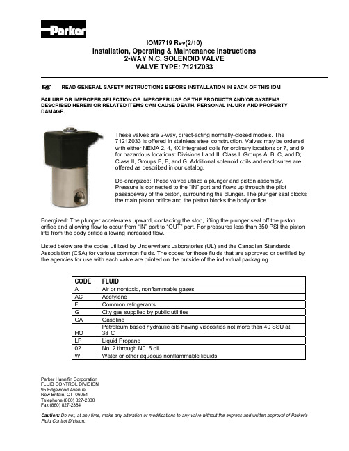
Installation, Operating & Maintenance Instructions2-WAY N.C. SOLENOID VALVEVALVE TYPE: 7121Z033Parker Hannifin CorporationFLUID CONTROL DIVISION95 Edgewood AvenueNew Britain, CT 06051Telephone (860) 827-2300Fax (860) 827-2384READ GENERAL SAFETY INSTRUCTIONS BEFORE INSTALLATION IN BACK OF THIS IOMFAILURE OR IMPROPER SELECTION OR IMPROPER USE OF THE PRODUCTS AND/OR SYSTEMSDESCRIBED HEREIN OR RELATED ITEMS CAN CAUSE DEATH, PERSONAL INJURY AND PROPERTYDAMAGE.These valves are 2-way, direct-acting normally-closed models. The7121Z033 is offered in stainless steel construction. Valves may be orderedwith either NEMA 2, 4, 4X integrated coils for ordinary locations or 7, and 9for hazardous locations: Divisions I and II; Class I, Groups A, B, C, and D;Class II, Groups E, F, and G. Additional solenoid coils and enclosures areoffered as described in our catalog.De-energized: These valves utilize a plunger and piston assembly.Pressure is connected to the “IN” port and flows up through the pilotpassageway of the piston, surrounding the plunger. The plunger seal blocksthe main piston orifice and the piston blocks the body orifice.Energized: The plunger accelerates upward, contacting the stop, lifting the plunger seal off the pistonorifice and allowing flow to occur from “IN” port to “OUT” port. For pressures less than 350 PSI the pistonlifts from the body orifice allowing increased flow.Listed below are the codes utilized by Underwriters Laboratories (UL) and the Canadian StandardsAssociation (CSA) for various common fluids. The codes for those fluids that are approved or certified bythe agencies for use with each valve are printed on the outside of the individual packaging.CODE FLUIDA Air or nontoxic, nonflammable gasesAC AcetyleneF Common refrigerantsG City gas supplied by public utilitiesGA GasolineHO Petroleum based hydraulic oils having viscosities not more than 40 SSU at38°CLP Liquid Propane02 No. 2 through N0. 6 oilW Water or other aqueous nonflammable liquidsInstallation, Operating & Maintenance Instructions2-WAY N.C. SOLENOID VALVEVALVE TYPE: 7121Z033Parker Hannifin CorporationFLUID CONTROL DIVISION95 Edgewood AvenueNew Britain, CT 06051Telephone (860) 827-2300Fax (860) 827-2384 For the maximum fluid temperatures, as well as valve ambient limitations, check the valve part number onthe nameplate and refer to the catalog or the outside of the shipping package.Installation InstructionsMounting position and pressure limits: Valves can be mounted directly on piping or by using the two(2) #10-32 NF threaded holes in the bottom of the valve body.The 7121Z033 valves are designed to be mounted vertically and upright for optimum life, performance,minimize wear and reduce the possibility of foreign matter accumulating inside the sleeve area.Piping: Remove protective closures from the ports. Connect line pressure to the inlet port. Use of Teflontape'; thread compound or sealants is permissible, but should be applied sparingly to male pipe threadsonly, Loctite primer #764 and pipe sealant #567 are recommended when using stainless steel fittings withstainless steel valve bodies.CAUTION: Do not allow foreign particles, Teflon tape, or thread compound to enter valve. Tighteningtorque should not exceed the 230 in-Lb for SAE-6 pipe thread. Do not use the sleeve or enclosure as alever when applying torque.Media filtration: Normally filtration is not required, but dirt or foreign material in the media may causeexcessive leakage, wear, or in exceptional cases, malfunction. If filtration is used, install the filter on theinlet side as close to the valve as possible. Clean periodically depending on service conditions.Lubrication: Lubrication is not required although air line lubrication will substantially increase valve life.Electrical connection: Electrical supply must conform to nameplate rating. Connect coil leads to theelectrical circuit using standard electrical practices in compliance with local authorities and the NationalElectrical Code.WARNING: Valves to be installed in Hazardous Locations must be outfitted with Hazardous Locationcoils only. Verify nameplate data and coil part number before installing the valve.WARNING: Turn off electrical power before connecting the valve to the power source.If the coil assembly is located in an inconvenient orientation, it may be reoriented to facilitate installation.Loosen coil assembly nut, rotate coil assembly to desired position, then retighten the nut with an inputtorque of43-53 in-lbs.Coil/enclosure temperature: Standard valves are supplied with coils designed for continuous duty service.Normal free space must be provided for proper ventilation. When the coil is energized continuously forlong periods of time, the coil assembly will become hot. The coil is designed to operate permanentlyunder these conditions. Any excessive heating will be indicated by smoking and/or odor of burning coilinsulation.Installation, Operating & Maintenance Instructions2-WAY N.C. SOLENOID VALVEVALVE TYPE: 7121Z033Parker Hannifin CorporationFLUID CONTROL DIVISION95 Edgewood Avenue New Britain, CT 06051Telephone (860) 827-2300 Fax (860) 827-2384For the maximum valve ambient conditions, as well as the fluid temperatures, check the valve part number on the nameplate and refer to the catalog.Note: Depending on service conditions, fluid being used, filtration, and lubrication, it may be required toperiodically clean and/or replace worn components. See Disassembly Instructions.CAUTION: Do not expose plastic or elastomeric materials to any type of commercial cleaning fluid. Partsshould be cleaned with a mild soap and water solution.Disassembly InstructionsWARNING: Depressurize system and turn off electrical power to the valve before attempting repair.To remove the coil assembly:For both ordinary and hazardous location constructions, unscrew the nut on the top of the coil assembly.The wave washer and coil assembly can now be removed.To disassemble the pressure vessel:CAUTION: If the sleeve assembly does not have a hex style flange, do not use a pipe wrench directly onthe sleeve. Instead, use a Skinner U99-011 wrench nut to remove and Install the sleeve assembly.Slide the Skinner U99-011 wrench nut over the sleeve tube. To unscrew the sleeve assembly, mate thewrench nut to the sleeve flange and turn the wrench nut. The plunger, return spring, and flange seal maynow be removed.Reassembly InstructionsWARNING: When replacing coils, valves equipped with Hazardous Location coils must use HazardousLocation replacement coils only. Verify nameplate data and coil part number before installing thereplacement coil.To reassemble the pressure vessel:Refer to exploded view drawings. Parts must be replaced in the order shown.With coil assembly repositioned on the sleeve, slide the wave washer over the sleeve and tighten coilassembly nut with an input torque of 43-53 in-Lbs.Installation, Operating & Maintenance Instructions2-WAY N.C. SOLENOID VALVEVALVE TYPE: 7121Z033Parker Hannifin CorporationFLUID CONTROL DIVISION95 Edgewood AvenueNew Britain, CT 06051Telephone (860) 827-2300Fax (860) 827-23841.0 GENERAL INSTRUCTIONS1.1. Scope: This safety guide is designed to cover general guidelines on the selection, installation, operation, and maintenance of these Products. This safety guide is a supplement to and is to be used with the specific Parker publication for the valve, assembly or related accessory being considered for use. Parker publications are available at or by calling 1-800-CPARKER.1.2. Fail-Safe: All Products can and do fail without warning for many reasons. Design all systems in a fail-safe mode so that failure of the Products will not endanger persons or property.1.3Distribution: Provide a copy of this safety guide to each person that is responsible for installation, operation, and maintenance of these Products. Do not select or use these Products without thoroughly reading and understanding this safety guide as well as the specific Parker publications for the Products considered or selected.1.4User Responsibility: Due to the wide variety of operating conditions and applications for these Products, Parker and its distributors do not represent or warrant that any particular Parker Fluid Control Product is suitable for any specific end use system. This safety guide does not analyze all technical parameters that must be considered in selecting a Product. The user, through its own analysis and testing, is solely responsible for:• Making the final selection of the Product;• Assuring that the user’s requirements are met and that the application presents no health or safety hazards;• Providing all appropriate health and safety warnings on the equipment on whichthe Products are used; and• Assuring compliance with all applicable government and industry standards.1.5Additional Questions: Call the appropriate Parker technical service department if you have any questions or require any additional information. See the Parker publication for the Product being considered or used, or call 1-800-CPARKER, or go to for telephone numbers of the appropriate technical service department.2.0 PRODUCT SELECTION INSTRUCTIONS2.1Selection: Consult the specific Parker Fluid Control publication for the Product being considered for use. Confirm the choice of Product with Parker Fluid Control’s technical consultants prior to placing orders for the Product or installing and using the Product.2.2Chemical Compatibility: Elastomer seal material used in the Products must be properly selected based on compatibility with the gases, liquids or additives being conveyed in the Product. Any exposure to non-compatible gases, liquids or additives may result in failure or degradation of the seals and leakage from the Product. Such failure or degradation could happen immediately or at any time over the life of the Product.3.0 PRODUCT ASSEMBLY AND INSTALLATION INSTRUCTIONS3.1 Inspection: Prior to assembly, all components must be checked for correct style, part number, and physical properties such as size or the presence of physical damage. Do NOT use any component that displays any signs of nonconformance.3.1.1 A careful examination of the Unit Valve and Unit Solenoid must be performed. If you purchase a Unit Valve and a Unit Solenoid, be sure that the last two digits of the Unit Valve match the first two digits of the Unit Solenoid. If they do not match then do not install.3.1.2 Check nameplate for correct catalog number, pressure, voltage and service. Do not install if unsuitable.3.1.3 Valves to be installed in Hazardous Locations must be outfitted with Hazardous Location coils only. Verify nameplate data and coil part number before installing the valve.3.2 Product Assembly: Do not assemble, install or use a Parker Fluid Control Division Product in any end use or3.2.1Threaded Connections: Proper procedures for the application of tape or liquid pipe sealant or thread compound must be followed so these contaminants do not enter the Product.3.2.2Sweating or Brazing: Products requiring the sweating or brazing of pipe connections must have precautions taken to protect the internal product components from excessive heat during the sweating or brazing operation. Follow the directions in the specific Parker Fluid Control Division publication for the Product in question.3.2.3Mounting: Check the specific Parker Fluid Control Division publication for the Product in question for limitations on mounting prior to mounting the Product.3.2.4Electrical Connection: Turn off electrical power before connecting or disconnecting the Product to the power source. Wiring must comply with local and national electrical codes.3.2.5 Voltage: Some coils contain solid state components that can be damaged by voltage spikes, transient voltage, over temperature, over voltage, or improper assembly. To protect against premature failure, please read the instructions in the specific Parker Fluid Control Division publication for the Product in question.3.2.6Port Connection: Parker Product operating parameters assume that the user connects the fluid to the proper inlet, outlet and exhaust ports. Connecting to the wrong ports may result in a complete failure or degraded performance. Use caution when applying and activating the fluid connection. Take the necessary precautions to protect personnel and property from injury and damage when turning on the fluid to the Product. Make sure the voltage is in the correct state (on or off) to control the applied pressure as required for the application in question.3.2.7Screw Terminal Coil and Terminal Box Assembly: When the DIN or screw terminal coils are used with the terminal box assembly, be sure to apply a wrench to the wrench flats on the conduit hub when installing electrical conduit.3.2.8Pressure: Turn off line pressure and bleed off trapped pressure from the lines before installing, removing or disassembling the Product.4.0PRODUCT AND SYSTEM OPERATION INSTRUCTIONS4.1Pressure Differential: Pressure differential dependent Products require a minimum pressure differential to operate properly. Make sure the chosen Product is sized properly for the application to maintain the required pressure differential across the Product.4.2System Check-out: Once installed, the Product installation must be tested to insure proper operation and that no external leakage exists. All safety equipment must be in place including but not limited to safety glasses, helmets, ear protection, splash guards, coveralls and any shields on the equipment. All air entrapment must be eliminated and the system pressurized to the maximum system pressure (at or below the Product maximum working pressure) and checked for proper function and freedom from leaks. Personnel must stay out of potentially hazardous areas while testing and using.5.0 PRODUCT MAINTENANCE AND REPLACEMENT INSTRUCTIONS5.1 Maintenance: Even with proper selection and installation, Product life or performance may be significantly reduced without a continuing maintenance program. The severity of the application, risk potential from a possible Product failure, and experience with any Product failures in the application or in similar applications should determine the frequency of the inspection and the replacement for the Products so that Products are replaced before any failure occurs. A maintenance program must be established and followed by the user and, at minimum, must include instructions 5.1.1 through 5.1.3. 5.1.1Product Lubrication and filtration: Almost all products require filtration. Consult the specific Parker Fluid Control Division publication for the Product in question. Note, too, that some Products require lubrication or filtration or both as a regular maintenance item due to the nature of the application’s environment. Consult the specific Fluid Control Division publication for the Product in question to determine this. Other Products, such as proportional valves, do not require any maintenance if the fluid is properly filtered. If a failure should occur, then these proportional valves should not be repaired but replaced.5.1.2Cleaning: Do not expose plastic or elastomeric materials to any type of commercial cleaning fluid. Parts should be cleaned with a mild soap and water solution.5.1.3Fluid Spills: Necessary precautions should be taken during maintenance to avoid exposing personnel or the surrounding area to any spilled fluid if the fluid is regulated, harmful, or damaging when exposed to or in contact with personnel or the surrounding environment.5.2Service and Repair:5.2.1General: Do not repair Products unless the specific Fluid Control Division publication for the Product in question allows this procedure. Not all Products can be safely repaired in the field. Repair and replacement must be in accordance with the specific Parker Fluid Control Division publication for the Product in question and any Parker replacement kit instructions.5.2.2Replacement Parts: If you purchase any replacement parts they must be original equipment manufactured by Parker Fluid Control Division.5.2.3Lock-Out / Tag-Out: Follow all lock-out and tag-out procedures before undertaking service or repairs. This includes de-energizing all electrical, fluid and mechanical energy sources.。
调节阀的安装要求

调节阀的安装要求嘿,朋友们!咱今天就来讲讲调节阀的安装要求。
这可不是小事儿啊,就好比你要给家里摆个重要的物件儿,得放对地方才行呢!安装调节阀啊,首先得选个好位置。
这位置就跟你挑座位似的,得舒舒服服的,还不能碍事。
不能随便找个犄角旮旯就给它安上了,那可不行!得考虑到它能不能正常工作,会不会被别的东西挡住,就像你在人群中得找个能看清舞台的地儿一样。
然后呢,管道得准备好了。
管道就像是调节阀的“路”,这路要是坑坑洼洼的,调节阀走起来能顺溜吗?所以管道得清理干净,不能有啥杂质、异物啥的。
这就好比你走路,路上要是有石头子儿,你不也得绊一下嘛!安装的时候,可得小心点儿。
别粗手粗脚的,要像对待宝贝似的。
螺丝得拧紧了,但也别太紧了,太紧了那不就像你把衣服扣子系得死死的,都透不过气来了。
螺丝松了也不行啊,那调节阀还不得晃悠啊,就跟人站不稳似的。
还有啊,密封得做好。
这密封就跟家里的窗户似的,要是密封不好,风啊雨啊不都进来啦?调节阀要是密封不好,那介质不就漏出来啦?那可就麻烦大了。
安装完了也别以为就万事大吉了。
你不得检查检查?就像你新做了一件衣服,不得试试合不合身啊?看看调节阀工作正不正常,有没有啥问题。
要是有问题,赶紧解决,别等出了大乱子才后悔。
咱再说说安装的角度。
这调节阀也有它喜欢的角度呢,你不能随便给它摆个姿势。
就像你睡觉,也得找个舒服的姿势不是?角度不对,它工作起来可能就不顺畅啦。
哎呀,这调节阀的安装要求可真不少呢!但咱可不能嫌麻烦,这可是关系到整个系统能不能正常运行的大事儿。
你想想,要是调节阀出了问题,那整个系统不就乱套啦?就像一部机器,一个零件坏了,整部机器可能都没法运转了。
所以啊,朋友们,安装调节阀的时候一定要认真、仔细,别马马虎虎的。
要把它当成家里的重要成员一样对待,给它找个好位置,让它舒舒服服地工作。
这样,咱的系统才能稳稳当当的,咱也才能放心啊!这可不是开玩笑的事儿,大家可得记住啦!。
阀门安装指南

阀门安装指南阀门安装的质量好坏,直接影响以后阀门的使用,因此,应引进施工单位及生产单位的高度重视。
1. 有一套正确的安装流程标准。
2. 安装施工必须小心,切忌撞击脆性材料制作的阀门。
3. 安装时的阀门是处于关闭状态。
4. 阀门的安装应按照阀门使用说明书和有关规定进行。
施工过程中要认真检查,精心施工。
阀门安装前,应试压合格后才进行安装,仔细检查阀门的规格、型号是否与图纸相符,检查阀门各零件是否完好,启闭阀门是否转动灵活自如,密封面有无损伤等,确认无误后,即可进行安装。
5. 安装前,应将阀门作一检查,核对规格型号,鉴定有无损坏,尤其对于阀杆。
还要转动几下,看是否歪斜,因为运输过程中,最易撞歪阀杆。
还要清除阀内的杂物。
6. 阀门安装位置不应防碍设备、管道及阀门本身的拆装和检修,必须方便于操作:即使安装暂时困难些,也要为操作人员的长期工作着想。
最好阀门手轮与胸口取齐,一般距地坪1.2m为宜,这样,开闭阀门比较省劲。
落地阀门手轮要朝上,不要倾斜,以免操作别扭。
7. 当阀门的中心与手轮离操作地面超过1.8m 时,应集中布置,并设置固定操作平台。
阀门较多的管道,阀门尽量集中在平台上,以便操作。
8. 对超过1.8m 并且不经常操作的单个阀门,可采用链轮、延伸杆、活动平台以及活动梯等设备。
当阀门安装在操作面以下时,应设置伸长杆,地阀应设置地井,为安全起见,地井应加盖。
9. 水平管道上的阀门的阀杆,最好垂直向上,不宜将阀杆向下安装。
阀杆向下安装,不便操作,不便维修,还容易腐蚀阀门出事故。
落地阀门不要歪斜安装,手轮要朝上,不要倾斜,以免操作别扭。
靠墙机靠设备的阀门,也要留出操作人员站立余地。
要避免仰天操作,尤其是酸碱、有毒介质等,否则很不安全。
10. 闸阀不要倒装(即手轮向下),否则会使介质长期留存在阀盖空间,容易腐蚀阀杆,而且为某些工艺要求所禁忌。
同时更换填料极不方便。
11. 升降式止回阀,安装时要保证其阀瓣垂直,以便升降灵活。
调节阀的安装

调节阀的安装2007年01月31日星期三 20:13调节阀安装时要注意如下问题:调节阀安装前的检验;在阀门操作的各个过程中,即安装、试验、操作和维修过程中的人员和设备的安全;在控制回路中作为最终控制元件的调节阀性能;若需手动操作时,要满足系统有效手动操作的安装要求;维修调节阀的可接近性;维修、操作和安装费用;由于机械或环境的需要,迫使阀门采取保护措施。
2.1 安装前的检验2.5 可接近性的考虑2.2 安全的考虑2.6 安装费用的考虑2.3 调节阀性能的考虑2.7 工厂安装2.4 手动操作的考虑2.8 使用工具设备的注意事项2.1 安装前的检验调节阀运到场地时,应立即进行检查,以确定是否符合规定,特别是安装尺寸、材质、附件等。
在此阶段,凡是在装运和装卸过程中造成的任何明显机械损伤,应及时处理,为保证调节阀在开车时能正常动作,使系统安全运行,还应检查如下项目:(1)外观检查(2)始终点偏差(3)全行程偏差(4)基本误差(5)正反行程偏差(6)泄漏量(7)所有辅助设备如限位开关、阀门定位器等操作检验。
2.2 安全的考虑在做阀门的配管设计和安装时,下述的各种问题和解决办法都必须考虑:(1)阀门可能泄漏,无论是在开始使用,还是在使用过程中,在填料函盖、法兰垫片或者在阀门损坏时形成的针眼上都可能泄漏.假若液体在非常苛刻的操作条件(温度和压力)下流过阀门,这对阀门可能会有所损坏,腐蚀性流体可能会聚在电缆槽中,易燃流体可能落到热的容器里,碱性溶液的热流体可能会伤害操作人员。
(2)在切断之后,阀门中的系统压力还可以继续保持一个时间,如果在维修这个阀门时要把它打开或取走的话,必须有降低这个压力的安全措施.同样也必须有排放积聚的有害液体的措施。
(3)在切断阀之间积留的大量高压流体可能会呈现相当大的力量,如果在排放调节阀压力的操作中粗心大意的话,可能发生严重的伤亡事故。
(4)可以设想,即使是好的设计,切断时也不可避免地会积留高压流体,因此建议:如果积聚液体的潜在能量具有很大危险性的话,应在调节阀的每一侧安装放空阀和(或)排放阀。
调节阀安装工艺

调节阀安装工艺本文档旨在介绍调节阀的安装工艺,帮助用户正确安装和使用调节阀。
1. 调节阀安装前准备在安装调节阀之前,您需要进行以下准备工作:- 确认调节阀的型号和规格,以及相应的技术参数。
- 审查调节阀的安装位置和管道连接方式。
- 准备安装需要的工具和设备,如扳手、螺丝刀等。
2. 调节阀安装步骤按照以下步骤进行调节阀的安装:1. 清洁工作:清理待安装的管道,确保其内部不含杂质和污垢。
同时检查阀门和管道的密封面是否清洁无损。
2. 应用密封材料:根据实际需要,在调节阀的密封面上涂抹适当的密封材料,以确保阀门与管道连接处的良好密封。
3. 手动操作:将调节阀安装在预定的位置上,用扳手和螺丝刀固定好。
然后手动操作调节阀,确保其开关灵活、无阻碍,并检查阀门传动装置的运行情况。
4. 连接管道:根据实际情况将调节阀与管道连接起来。
确保管道连接牢固、无漏水,并检查阀门的正常运行情况。
5. 验证操作:在调节阀安装完毕后,进行验证操作,检查阀门的调节性能和密封状态是否符合要求。
如果发现问题,及时进行调整或更换相关部件。
3. 安装后的注意事项在调节阀安装完毕后,务必注意以下事项:- 定期检查调节阀的工作状态和密封性能,若有异常现象及时处理。
- 防止调节阀受到剧烈的压力或振动,避免对其造成损坏。
- 定期对阀门运动部件进行润滑维护,确保其灵活可靠。
请按照以上步骤和注意事项进行调节阀的安装,确保其正常运行和长久使用。
> 注意:本文档所述内容仅为一般性指导,具体安装步骤可能会因具体情况而有所变化。
请在安装前仔细阅读制造商提供的详细安装说明和操作手册,并遵从相关法律法规要求。
7调节阀调校与安装

调节阀的调校与安装1、调节阀的调校世界上各个国家的调节阀生产厂家和各个公司对调节阀产品的性能测试标准和方法都不太一样。
测试项目很多,一般可以分为产品的出厂检验项目和型式的测试项目。
产品的出厂检验项目是必不可少的,即对每一台产品的这些性能一定要进行检查,主要指标包括各项静特性(基本误差、始终点偏差、额定行程偏差、回差、死区、重复性、再现性误差等项),还有气密性、密封性、泄漏性、耐压强度和外观等项,这些都是出厂前的必查项目,生产厂家必须保证所有各项的技术指标都合乎标准,用户验收也按这些项目进行。
1.1气动调节阀的校验的主要项目以下项目按调节阀的静特性参数进行见(P160)1)基本误差——将规定的输人信号平稳地按增大或减小方向输入执行机构气室(或定位器),测量各点所对应的行程值,计算出实际“信号一行程”之间理论关系的各点误差,其最大值即为基本误差。
校验点应至少包括信号范围0%、25%、50%、75%、100%这5个点。
测量仪表基本误差限应小于被校阀基本误差限的1/4。
2)始终点偏差——信号的下限(始点) 处的基本误差即为始点偏差,信号的上限(终点)处的基本误差即为终点偏差。
始终点偏差用调节阀额定行程的百分数表示。
3)额定行程偏差——将120%的信号加入执行机构气室,从100%到120%信号阀杆再走的行程与额定行程之比,即为额定行程偏差(其目的是保证气关阀能关闭到位)。
4)回差——在同一输入信号上所测得的正反行程的最大差值即为回差。
5)死区——输入信号正反方向变化不致引起行程有任何可察觉变化的有限空间。
6)气密性测试进入执行机构气室的空气,一旦泄漏之后,就会消耗空气,消耗动力,而且空气压力不能保持给定值,使执行机构的推力减小,动作缓慢,所以对气密性进行严格检查十分必要。
(1)气密性的定义;薄膜式和活塞式执行机构的气室,在保证的试验气压下,在规定的时间内不漏气的性能,称为气密性。
(2)气密性的试验方法;气动执行机构的气密性试验有两种方法。
- 1、下载文档前请自行甄别文档内容的完整性,平台不提供额外的编辑、内容补充、找答案等附加服务。
- 2、"仅部分预览"的文档,不可在线预览部分如存在完整性等问题,可反馈申请退款(可完整预览的文档不适用该条件!)。
- 3、如文档侵犯您的权益,请联系客服反馈,我们会尽快为您处理(人工客服工作时间:9:00-18:30)。
Pressure Reducing Valve Type 2357-1/-6Excess Pressure Valve Type 2357-2/-7ContentsContents Page1Design and principle of operation. . . . . . . . . . . . . . . . . . . . . .32Installation. . . . . . . . . . . . . . . . . . . . . . . . . . . . . . . . .5 2.1Mounting position. . . . . . . . . . . . . . . . . . . . . . . . . . . . . .5 2.2Shut-off valve and pressure gauge. . . . . . . . . . . . . . . . . . . . . .53Operation. . . . . . . . . . . . . . . . . . . . . . . . . . . . . . . . .6 3.1Set point adjustment. . . . . . . . . . . . . . . . . . . . . . . . . . . . .6 3.2Changing the set point range. . . . . . . . . . . . . . . . . . . . . . . .74Dimensions in mm and weights. . . . . . . . . . . . . . . . . . . . . . .92EB 2557 EN1Design and principle of operationThe pressure regulators maintain the pressure at an adjusted set point and are particularly suitable for cryogenic applications.Type2357-1and Type2357-6Regulators (globe valves)The regulators act as pressure reducing valves when the medium flows from port(A) to port(B).When no pressure is applied,the valve is open.The pressure downstream of the valve(B)is transmitted to the operating diaphragm(3). The resulting positioning force moves the valve plug(2)in relation to the spring force, which can be adjusted at the set point ad-juster(10).The valve closes as the pressure downstream of the valve (B) increases. When the regulators are used as pressure build-up regulators,the medium flows from port(B)to port(A).The pressure upstream of the valve(B)is transmitted to the operating di-aphragm(3).The valve closes as the pressure upstream of the valve increases.The pressure build-up regulator additionally assumes the function of a safety valve, depressurizing the pressurized valve when the set point is exceeded by more than5bar. When the pressure has overcome the force of the springs located on top,the valve opens to balance the pressures.Type2357-2and Type2357-7Regulators (angle valves)The regulators functioning as excess pressure valves,the medium always flows from port (A)to port(B).When no pressure is applied, the valve is closed.The pressure at port(A) acts on the operating diaphragm(3)in the valve body.The resulting force opposes the adjustable spring force.As the pressure in-creases,the valve opens until the set point is reached.Regulators functioning as excess pressure valves can optionally be equipped with a non-return unit(12)which prevents the me-dium from flowing back.TypetestingThe regulator versions for PN50have been typetested by the German Technical Inspec-torate(TÜV).The test mark is available on re-quest.EB 2557 EN3Safety instructionsDesign and principle of operation4EB 2557 EN2Installation2.1Mounting positionThe pressure regulator must be installed with the actuator housing hanging downward. Observe the following directions of flow:4(A) to (B) in pressure reducing valves 4(B) to (A) in pressure build-up regulatorswith safety function4(A) to (B) in excess pressure valvesequipped with a non-return unit. Port (B)must point upward.Note:Make sure that any impurities carried along by the process medium in the con-nected pipelines do not impair the proper functioning and especially the tight shut-off of the regulator.2.2Shut-off valve and pressuregaugeWe recommend installing a hand-operated shut-off valve both upstream and downstream of the regulator to be able to shut down the plant for cleaning and maintenance,and when the plant is not used for longer periods of time.Install a pressure gauge both upstream and downstream of the regulator to monitor the pressures prevailing in the plant.EB 2557 EN5Installation3Operation3.1Set point adjustmentThe pressure regulator is adjusted at the factory to the set points listed in the table.However,you can change them by turning the set point adjuster (10).When pressure gauges are installed in the connected pipelines,you can adjust the de-sired set point directly while monitoring the corresponding pressure gauge.When no pressure gauge is installed,use the adjustment diagram to adjust the set point.To increase the set point,turn the set point ad-juster into the body,and to decrease the set point,turn the set point adjuster out of the body.1.Undo the lock nut to allow the set pointadjuster to move freely.2.Determine the difference between thefixed set point (table below) and the re-quired set point. Turn the set point ad-juster the required amount of turns as specified in the diagram.Any subsequent change in set point can be also be made by determining the re-quired number of turns using the specifi-cations listed in the table in “Set point change per turn”.3.Secure the setting with the lock nut.6EB 2557 ENSet point adjustment3.2Changing the set point range The set point ranges adjusted by the manu-facturer can be changed subsequently by ex-changing the set point springs(8)and the op-erating diaphragms (3).We recommend to contact the manufacturer to perform this for you.1.Unscrew the lock nut(11).Completely re-lieve the set point springs(8)of tension by turning the set point adjuster(10)in a counterclockwise direction.2.Place the lower section of the body(9)into a vise,but do not clamp it.Better:usea box wrench with width across flats=55mm.Unscrew the body(1)using an open-end wrench with width across flats =36mm and remove all parts from the lower section of the body.Be careful not to damage the operating diaphragms(3).3.Install set point spring(s)for the requiredset point range,the spring plates(7),the ball(6)and the diaphragm plate(5)in the lower section of the body.4.Place the required number of dia-phragms(see table of spare parts)onto the diaphragm plate and replace the PTFE gasket(4)of the valve body,if re-quired.5.Carefully place the body onto the lowersection of the body.Then screw the body onto the lower section of the body using a tightening torque of approx.180Nm for PN40and approx.250Nm for PN50.EB 2557 EN7OperationSpare partsNote:Accessories and spare parts are al-ways delivered"free from oil and grease for oxygen service."8EB 2557 ENDimensions in mm and weights 4Dimensions in mm and weightsEB2557EN910EB2557ENEB2557EN11SAMSON AG ·MESS- UND REGELTECHNIKWeismüllerstraße 3 ·60314 Frankfurt · Germany Phone: +49 69 4009-0 ·Fax: +49 69 4009-1507Internet:http://www.samson.de EB 2557 EN S /Z2009-02。