实验六-HSRP与上行链路跟踪
6.1.8 HSRP接口跟踪[共2页]
![6.1.8 HSRP接口跟踪[共2页]](https://img.taocdn.com/s3/m/7cf6c9c114791711cd7917be.png)
220第6章第一跳冗余协议
义的条件不满足时,路由器优先级则会降低。
降低的数值可以手动配置,默认值为10。
6.1.8 HSRP接口跟踪
HSRP内置了一种机制,用于检测链路故障并启用HSRP相关进程。
如图6-17中的左图所示,R1和R2配置了HSRP组。
R2配置成了活动默认网关。
当R2启用HSRP的接口(下行链路)发生故障时,R1会接管R2成为活动路由器。
图6-17 未启用接口跟踪特性的HSRP
如果R2的上行链路故障会发生什么呢?由于R2上行链路未启用HSRP,因此其故障不会影响到HSRP。
R2仍然作为活动默认网关存在。
所有从PC 1去往服务器的流量都会流经R2,之后再路由给R1并转发至服务器,从而产生了一个低效率的流量路径,如图6-17中的右图所示。
HSRP提供了一种针对此类问题的解决方案:HSRP接口跟踪技术。
接口跟踪(track)允许配置用户在路由器上配置某个接口,HSRP进程通过监控这一接口状态来更改特定组的HSRP优先级。
如果跟踪的接口的2层协议(link protocol)变为down状态,此路由器的HSRP优先级将会降低,这么做的目的是使另外一台带有更高优先级的HSRP路由器变成活动路由器。
当然抢占特性需要事先开启。
继续来看之前的拓扑。
假定图6-18中的R2上行链路出现了故障,但这次在R2的上行链路上配置了HSRP接口跟踪技术,并检测到了这一故障,因此R2的HSRP优先级会降低20。
在启动了抢占特性的前提下,由于R1带有最高的优先级,因此将会接管成为新的HSRP活动路由器。
对于Cisco交换机HSRP协议track选项的分析

对于Cisco交换机HSRP协议track选项的分析对于Cisco交换机HSRP协议track选项的分析交换机上部分配置代码如下:track 1 ip route 10.1.21.128 255.255.0.0 metric thresholdthreshold metric up 1 down 2track 10 ip route 10.2.21.128 255.255.255.0 metric thresholdthreshold metric up 63 down 64interface Vlan10ip address 10.2.1.1 255.255.255.0standby 10 ip 10.2.1.254standby 10 priority 200standby 10 preemptstandby 10 track 1 decrement 60从HSRP上看,是在SVI上实现了HSRP功能,同时使⽤了track功能实现了路由跟踪的功能。
track命令可以是对接⼝和路由的跟踪监测,可以使⽤track interface对端⼝进⾏状态跟踪,也可以对路由进⾏跟踪;threshold 单词的中⽂意思为阈值,也就是⼀个门限值的概念;对于命令的解释:track 10 ip route 10.2.21.128 255.255.255.0 metric threshold 这⾏命令的意思是,设⽴⼀个路由的监测命令,命令的序列号是10,监测的路由是10.2.21.128 255.255.255.0,监测点是该路由的metric值,⽽引起监测异动的阈值由threshold指定,threshold metric up 63 down 64中指定,如果metric值在63以下则认为为路由可达,⽽64以上则为不可达。
standby 10 track 10 decrement 60,该命令对序号为10的track监测命令定义操作,如果监测到该监测命令中引起路由不可达的情况,该HSRP组的HSRP成员的优先级(priority)减少60,本例为200-60。
HSRP与链路追踪

链路追踪的概念:当网络中存在着HSRP的备份路由器时,可以配置HSRP的上行链路追踪,当指定的追踪接口down掉时,马上减小该HSRP设备的优先级,使另一个备份设备能马上被激活成为ACTIVE状态,并接替down掉的设备继续引导路由数据,实现网络的畅通性拓扑规划:案例实施:1)、各设备配置:R1配置:interface Loopback0ip address 202.102.12.1 255.255.255.0interface Serial1/0ip address 172.16.0.1 255.255.255.252serial restart-delay 0clock rate 64000!interface Serial1/1ip address 172.16.0.5 255.255.255.252serial restart-delay 0clock rate 64000R2配置:interface FastEthernet0/0.10encapsulation dot1Q 10ip address 192.168.10.1 255.255.255.0ip nat insideip virtual-reassemblystandby 10 ip 192.168.10.254standby 10 priority 120standby 10 preemptstandby 10 track Serial1/0 30!interface FastEthernet0/0.20encapsulation dot1Q 20ip address 192.168.20.1 255.255.255.0ip nat insideip virtual-reassemblystandby 20 ip 192.168.20.254standby 20 preemptinterface Serial1/0ip address 172.16.0.2 255.255.255.252ip nat outsideip virtual-reassemblyserial restart-delay 0ip route 0.0.0.0 0.0.0.0 Serial1/0ip nat inside source list 100 interface Serial1/0 overloadR3配置:interface FastEthernet0/0.10encapsulation dot1Q 10ip address 192.168.10.2 255.255.255.0ip nat insideip virtual-reassemblystandby 10 ip 192.168.10.254standby 10 preempt!interface FastEthernet0/0.20encapsulation dot1Q 20ip address 192.168.20.2 255.255.255.0ip nat insideip virtual-reassemblystandby 20 ip 192.168.20.254standby 20 priority 120standby 20 preemptstandby 20 track Serial1/1 30interface Serial1/1ip address 172.16.0.5 255.255.255.252ip nat outsideip virtual-reassemblyserial restart-delay 0ip route 0.0.0.0 0.0.0.0 Serial1/1ip nat inside source list 100 interface Serial1/1 overloadSw1配置:interface FastEthernet0/0switchport mode trunk!interface FastEthernet0/1switchport mode trunk!interface FastEthernet0/2switchport mode trunk!interface FastEthernet0/3switchport access vlan 10!interface FastEthernet0/4switchport access vlan 20vlan databasevlan 10vlan 20Sw2配置:interface FastEthernet0/0switchport mode trunk!interface FastEthernet0/1switchport mode trunk!interface FastEthernet0/2switchport mode trunk!interface FastEthernet0/3switchport access vlan 10!interface FastEthernet0/4switchport access vlan 20vlan databasevlan 10vlan 20PC1配置:no ip routinginterface FastEthernet0/0ip address 192.168.10.100 255.255.255.0 no ip route-cacheduplex autospeed autoip default-gateway 192.168.10.254PC2配置:no ip routinginterface FastEthernet0/0ip address 192.168.20.100 255.255.255.0 no ip route-cacheduplex autospeed autoip default-gateway 192.168.20.254PC3配置:no ip routinginterface FastEthernet0/0ip address 192.168.10.200 255.255.255.0 no ip route-cacheduplex autospeed autoip default-gateway 192.168.10.254PC4配置:no ip routinginterface FastEthernet0/0ip address 192.168.20.200 255.255.255.0no ip route-cacheip default-gateway 192.168.20.2542)、配置完成后查看R2和R3的HSRP信息:R2:R3:此时在PC2上跟踪一下到202.102.12.1的路由情况在PC3上跟踪到202.102.12.1的路有情况此时将R1的接口S1/0设置为shutdown模式,再查看HSRP信息:R2:R3:此时再在PC1和PC2上跟踪到202.102.12.1的路由,发现R3自动接管原先的路由:PC1:PC3:。
HSRP实验过程及报告

目录HSRP实验过程及报告 (2)实验环境: (2)实验拓扑: (2)实验目的: (2)实验过程: (3)1 配置交换机 (3)2 测试HSRP (5)3测试HSRP跟踪 (8)实验总结: (10)HSRP实验过程及报告实验环境:DynamipsGUI模拟器模拟出4台cisco3640三层交换机。
两台开启HSRP协议,设备之间使用Ethernetchannel绑定的两条线路互联。
其余两台交换机分别连接到这两台交换机。
实验拓扑:实验拓扑如图1实验目的:熟悉HSRP协议,验证HSRP网关冗余特性,测试HSRP抢占过程及HSRP接口跟踪。
实验过程:1 配置交换机在交换机SW1配置F0/0.F0/1接口加入channel-group 1 并将port-channel 1 配置为trunk模式。
SW1(config)#int range f0/0 - 1SW1(config-if-range)#channel-group 1 mode onCreating a port-channel interface Port-channel1SW1(config-if-range)#*Mar 1 01:23:58.639: %EC-5-BUNDLE: Interface Fa0/0 joined port-channel Po1 *Mar 1 01:23:58.935: %EC-5-BUNDLE: Interface Fa0/1 joined port-channel Po1 SW1(config-if-range)#*Mar 1 01:24:01.415: %LINEPROTO-5-UPDOWN: Line protocol on Interface Port-channel1, changed state to upSW1(config-if-range)#exitSW1(config)#int port-channel 1SW1(config-if)#switchport mode trunkSW1(config-if)#endSW1#sh etherchannel suFlags: D - down P - in port-channelI - stand-alone s - suspendedR - Layer3 S - Layer2U - in useGroup Port-channel Ports-----+------------+-----------------------------------------------------------1 Po1(SU) Fa0/0(P) Fa0/1(P)在交换机SW2上同样的配置。
HSRP

这部分的讲解要结合幻灯片高可用性:1.HSRP(Hot Standby Routing Protocol):热备份路由协议2.VRRP(Virtual Router Redundancy Protocol):虚拟路由器冗余协议3.GLBP(Gateway load Balancing Protocol):网关负载均衡协议这3个协议都是用来保证网关的备份的HSRP1.思科私有的2.一个虚拟IP地址,一个虚拟MAC地址虚拟IP地址不能和真实IP地址相同虚拟MAC地址:0000.0c07.acXX,其中XX是组号3.一主一辅4.HSRP默认优先级是100,被跟踪的接口不可用后优先级默认降低105.HSRP的6种状态(1)Initial:初始状态,修改配置或接口刚启动时处于这个状态(2)Learn:学习状态,等待活跃路由器发送Hello 消息,收到后就进入监听状态(3)Listen:监听状态,在HSRP组中,除活跃路由器和备用路由器外,其他路由器都处于这种状态。
说白了,这个状态就是用来选举的,如果被选举是备用状态或者是活跃状态,就进入speak状态(4)speak:发言状态,处于发言状态的路由器定期地发送Hello消息,如果在speak状态发现了更优秀的Hello包,此时就转化成listen状态(5)Standby:备用状态,定期发送Hello消息(6)Active:活跃状态,定期发送Hello消息HSRP使用的包:hello,辞职和政变6.配置的时候一定要禁用定向广播命令是:no ip redirects7.关于HSRP的实验(1)路由器上基本配置(2)交换机上基本配置(3)跟踪(4)负载均衡8配置主设备配置3句话standby 1 ip 虚拟IP地址standby 1 preempt //让设备支持抢占功能standby 1 priority 优先级备份设备配置2句话standby 1 ip 虚拟IP地址standby 1 preemptVRRP1.公有的2.一个虚拟IP地址,一个虚拟MAC地址虚拟IP地址可以和真实IP地址相同虚拟MAC地址:0000.5e00.01XX,其中XX是组号3.一主多辅4.VRRP默认优先级是100,不支持跟踪5.协议号112,组播地址224.0.0.18,默认通告间隔1s6.VRRP默认有抢占机制7.关于VRRP的实验(1)路由器上基本配置(2)交换机上基本配置(3)负载均衡HSRP与VRRP之间的区别:1.HSRP是私有的,VRRP是共有的2.HSRP是一主一辅,VRRP是一主多辅3.HSRP支持跟踪,VRRP没有跟踪机制4.HSRP的虚拟IP地址不能和真实IP地址相同,VRRP的虚拟IP地址和真实的IP地址相同5.HSRP中主、辅设备都发送Hello包,VRRP中只有主设备发送Hello包GLBP1.思科私有的2.一个虚拟IP地址,多个虚拟MAC地址3.GLBP和HSRP,VRRP的最大不同在于:可以提供负载均衡4.两个术语:(1)AVF:active virtual forwarder(2)AVG:active virtual gateway5.GLBP的工作原理:(1)GLBP组选举一个AVG,所有组成员都叫做AVF (2)AVG给整个组分配虚拟MAC地址,即每个AVF分配到一个虚拟MAC地址(3)AVG负责回复用户的ARP请求,每次给的虚拟MAC 地址不同,以这种方式实现负载均衡(4)每个AVF负责转发自己负责的那个虚拟MAC的数据6.GLBP支持3种负载均衡的模式(1)host-dependent:确保主机始终使用同一个虚拟MAC地址(2)round-robin:每次轮流地分配AVF的虚拟MAC地址(3)weighted:前往AVF的流量取决于AVF的权重7.关于GLBP的实验(1)路由器上基本配置(2)交换机上基本配置。
实验六-HSRP与上行链路跟踪

一、实验目的1、组网要求企业总部局域网采用两台核心交换机组网来提高网络可靠性,为防止二层环路,需要全网运行STP;将SW1部署为跟网桥,SW2部署为备份跟网桥,并将接入PC的接口配置为portfast 端口;SW1—SW2之间使用链路捆绑进一步提高可靠性;同时,部署HSRP为部vlan提供网关冗余。
本局域网有4个vlan,生产业务vlan10,办公业务vlan11,二层交换机网管vlan8;将SW1部署为vlan8/10/11的主网关,将SW2部署为vlan11的主网关;要求vlan10,vlan11的主网关跟踪上行链路。
2、测试HSRP主备网关倒换。
3、分析PC1 ping PC2的三层通信过程和二层通信过程。
二、实验拓扑三、实验容1、基本信息配置SW1Switch>enable//进入全局模式Switch#config terminal//进入特权模式Switch(config)#hostname SW1//设置主机名SW1(config)#no ip domain lookup//禁用域名查找SW1(config)#enable password ip//设置进入特权模式密码SW1(config)#line console 0//连接到console线口SW1(config-line)#logging synchronous //自动换行SW1(config-line)#exec-t 0//超时为0SW1(config-line)#password ip//设置进入console线口的密码SW1(config-line)#login//进入console线口是需要进行认证SW1(config-line)#exit//退出console线口SW1(config)#line aux 0//进入线口SW1(config-line)#logging synchronous //自动换行SW1(config-line)#exec-t 0//超时为0SW1(config-line)#password bluefox//设置进入本线口的密码SW1(config-line)#login//设置进入线口是进行认证SW1(config-line)#exit//退出线口SW1(config)#line vty 04//进入线口SW1(config-line)#logging synchronous //自动换行SW1(config-line)#exec-t 0//超时为0SW1(config-line)#password bluefox//设置进入密码SW1(config-line)#login//设置进入是进行认证SW1(config-line)#exit//退出线口SW2Switch>enableSwitch#config terminalSwitch(config)#hostname SW2SW2(config)#no ip domain lookupSW2(config)#enable password ipSW2(config)#line console 0SW2(config-line)#logging synchronous SW2(config-line)#exec-t 0SW2(config-line)#password ipSW2(config-line)#loginSW2(config-line)#exitSW2(config)#line aux 0SW2(config-line)#logging synchronous SW2(config-line)#exec-t 0SW2(config-line)#password bluefoxSW2(config-line)#loginSW2(config-line)#exitSW2(config)#line vty 04SW2(config-line)#logging synchronous SW2(config-line)#exec-t 0SW2(config-line)#password bluefoxSW2(config-line)#loginSW2(config-line)#exitSW3SW3>enableSW3#config terminalSW3(config)#hostname SW3SW3(config)#no ip domain lookupSW3(config)#enable password ipSW3(config)#line console 0SW3(config-line)#logging synchronous SW3(config-line)#exec-t 0SW3(config-line)#password ipSW3(config-line)#loginSW3(config-line)#exitSW3(config)#line aux 0SW3(config-line)#logging synchronous SW3(config-line)#exec-t 0SW3(config-line)#password bluefoxSW3(config-line)#loginSW3(config-line)#exitSW3(config)#line vty 04SW3(config-line)#logging synchronous SW3(config-line)#exec-t 0SW3(config-line)#password bluefoxSW3(config-line)#loginSW3(config-line)#exitRT5Router>enableRouter#config terminalRouter(config)#hostname RT5RT5(config)#no ip domain lookupRT5(config)#enable password ipRT5(config)#line console 0RT5(config-line)#logging synchronous RT5(config-line)#exec-t 0RT5(config-line)#password ipRT5(config-line)#loginRT5(config-line)#exitRT5(config)#line aux 0RT5(config-line)#logging synchronous RT5(config-line)#exec-t 0RT5(config-line)#password bluefox RT5(config-line)#loginRT5(config-line)#exitRT5(config)#line vty 04RT5(config-line)#logging synchronous RT5(config-line)#exec-t 0RT5(config-line)#password bluefox RT5(config-line)#loginRT5(config-line)#exitRT6Router>enableRouter#config terminalRouter(config)#hostname RT6RT6(config)#no ip domain lookupRT6(config)#enable password ipRT6(config)#line console 0RT6(config-line)#logging synchronous RT6(config-line)#exec-t 0RT6(config-line)#password ipRT6(config-line)#loginRT6(config-line)#exitRT6(config)#line aux 0RT6(config-line)#logging synchronous RT6(config-line)#exec-t 0RT6(config-line)#password bluefox RT6(config-line)#loginRT6(config-line)#exitRT6(config)#line vty 04RT6(config-line)#logging synchronousRT6(config-line)#exec-t 0RT6(config-line)#password bluefoxRT6(config-line)#loginRT6(config-line)#exit2、创建vlanSW1SW1#vlan database//进入vlan database模式SW1(vlan)#vlan 8//创建vlan8SW1(vlan)#vlan 10//创建vlan10SW1(vlan)#vlan 11//创建vlan11SW1(vlan)#exit//退出vlan database模式、SW2SW2#vlan database//进入vlan database模式SW2(vlan)#vlan 8//创建vlan8SW2(vlan)#vlan 10//创建vlan10SW2(vlan)#vlan 11//创建vlan11SW2(vlan)#exit//退出vlan database模式SW3SW3#vlan database//进入vlan数据库SW3(vlan)#vlan 8//创建vlan8SW3(vlan)#vlan 10//创建vlan10SW3(vlan)#vlan 11//创建vlan11SW3(vlan)#exit//退出vlan database模式4、跟网桥配置SW1SW1(config)#spanning-tree vlan 8 priority 0 //配置sw1为vlan8的跟网桥SW1(config)#spanning-tree vlan 10 priority 0//配置sw1为vlan10的跟网桥SW1(config)#spanning-tree vlan 11 priority 0//配置sw1为vlan11 的跟网桥注:模拟器上不支持批量配置vlan跟网桥,只能一个一个配置SW2SW2(config)#spanning-tree vlan 8 priority 4096//配置sw2为vlan8的备份网桥SW2(config)#spanning-tree vlan 10 priority 4096//配置sw2为vlan10 的备份网桥SW2(config)#spanning-tree vlan 11 priority 4096//配置sw2为vlan11的备份网桥5、二层链路捆绑SW1SW1(config)#interface range fastEthernet 0/1 -2//进入端口1和2SW1(config-if-range)#switchport trunk encapsulation dot1q //设置trunk封装协议为dot1qSW1(config-if-range)#switchport mode trunk//端口为trunk模式SW1(config-if-range)#switchport trunk allowed vlan all//配置trunk允许所有vlan通过SW1(config-if-range)#channel-group 2 mode on//将端口1和2划分到通道组2中SW1(config-if-range)#exit//退出端口1和2SW2SW2(config)#interface range fastEthernet 0/1 -2//进入端口1 和2SW2(config-if-range)#switchport trunk encapsulation dot1q //配置trunk封装协议为dot1qSW2(config-if-range)#switchport mode trunk//配置端口为trunk接口SW2(config-if-range)#switchport trunk allowed vlan all//配置trunk允许所有vlan通过SW2(config-if-range)#channel-group 2 mode on//将接口1和2 划分到通道组2中SW2(config-if-range)#exit//退出接口6、二层接口配置SW1SW1(config)#interface fastEthernet 0/3//进入接口SW1(config-if)#switchport trunk encapsulation dot1qSW1(config-if)#switchport mode trunk//配置接口为trunk接口SW1(config-if)#switchport trunk allowed vlan all//配置trunk允许所有vlan通过SW1(config-if)#exit//退出端口SW2SW2(config)#interface fastEthernet 0/3//进入接口SW2(config-if)#switchport trunk encapsulation dot1q//配置trunk封装协议为dot1qSW2(config-if)#switchport mode trunk//配置接口为trunk接口SW2(config-if)#switchport trunk allowed vlan all//配置trunk允许所有vlan通过SW2(config-if)#exit//退出接口SW3SW3(config)#interface fastEthernet 0/10//进入接口SW3(config-if)#switchport mode access//配置接口为access接入模式SW3(config-if)#switchport access vlan 10//将接口划分到vlan10 中SW3(config-if)# spanning-tree portfast//设置接口为portfast模式,SW3(config-if)#exit//退出接口SW3(config)#interface fastEthernet 0/11//进入接口SW3(config-if)#switchport mode access//配置接口为access接入模式SW3(config-if)#switchport access vlan 11//将接口划分到vlan11中SW3(config-if)# spanning-tree portfast//设置接口为portfast模式SW3(config-if)#exit//退出接口SW3(config)#interface range fastEthernet 0/1 -2//进入接口1和2,此处为批量设置,因为两个接口的配置相同SW3(config-if-range)#switchport trunk encapsulation dot1qSW3(config-if-range)#switchport mode trunk//配置接口为trunk模式SW3(config-if-range)#switchport trunk allowed vlan all //配置trunk允许所有vlan通过SW3(config-if-range)#exit//退出接口1和27、二层设备网管地址配置SW3(config)#interface vlan 8//为sw3配置网管地址SW3(config-if)#ip address 192.168.8.132 255.255.255.128 //配置ip地址SW3(config-if)#no shutdown//启用端口SW3(config-if)#exit//退出8、三层接口配置SW1SW1(config)#interface vlan 8//配置vlan8的路由点SW1(config-if)#ip address 192.168.8.130 255.255.255.128 //配置ip地址SW1(config-if)#no shutdown//启用SW1(config-if)#exit//退出SW1(config)#interface vlan 10//配置vlan10的路由点SW1(config-if)#ip address 192.168.10.2 255.255.255.0//配置ip地址SW1(config-if)#no shutdown//启用SW1(config-if)#exit//退出SW1(config)#interface vlan 11//配置vlan11的路由点SW1(config-if)#ip address 192.168.11.2 255.255.255.0//配置ipSW1(config-if)#no shutdown//启用SW1(config-if)#exitSW2SW2(config)#interface vlan 8//配置vlan8的路由点SW2(config-if)#ip address 192.168.8.131 255.255.255.128 //配置ip地址SW2(config-if)#no shutdown//启用SW2(config-if)#exit//退出SW2(config)#interface vlan 10//配置vlan10的路由点SW2(config-if)#ip address 192.168.10.3 255.255.255.0//配置ip地址SW2(config-if)#no shutdown//启用SW2(config-if)#exit//退出SW2(config)#interface vlan 11//配置vlan11的路由点SW2(config-if)#ip address 192.168.11.3 255.255.255.0//配置ipSW2(config-if)#no shutdown//启用SW2(config-if)#exitSW1上行链路SW1(config)#interface fastEthernet 0/12//进入接口SW1(config-if)#no switchport//配置接口为三层接口SW1(config-if)#ip address 192.168.9.1 255.255.255.252 //为接口配置IP地址SW1(config-if)#no shutdown//打开接口SW1(config-if)#exit//退出接口RT5(config)#interface ethernet 0/0//进入接口RT5(config-if)#ip address 192.168.9.2 255.255.255.252 //配置IP地址RT5(config-if)#no shutdown//打开接口RT5(config-if)#exit//退出接口SW2上行链路SW2(config)#interface fastEthernet 0/12//进入接口SW2(config-if)#no switchport//配置接口为三层接口SW2(config-if)#ip address 192.168.9.5 255.255.255.252//配置IP地址SW2(config-if)#no shutdown//打开接口SW2(config-if)#exit//退出接口RT6(config)#interface ethernet 0/0//进入接口RT6(config-if)#ip address 192.168.9.6 255.255.255.252//配置IP地址RT6(config-if)#no shutdown//打开端口RT6(config-if)#exit//退出端口9、HSRP部署SW1上的HSRP配置SW1(config)#interface vlan 8SW1(config-if)#standby 8 ip 192.168.8.129//配置HSRP组8的虚IPSW1(config-if)#standby 8 priority 120//设置组8 的优先级SW1(config-if)#standby 8 preempt//配置组8的抢占SW1(config-if)#exitSW1(config)#interface vlan 10SW1(config-if)#standby 10 ip 192.168.10.1//配置组10 的虚IPSW1(config-if)#standby 10 priority 120//配置组10的优先级SW1(config-if)#standby 10 preempt配置组10的抢占SW1(config-if)#standby 10 track fastethernet 0/12 30//配置HSRP组10跟踪上连接口,上连接口DOWN时优先级减30 SW1(config-if)#exitSW1(config)#interface vlan 11SW1(config-if)#standby 11 ip 192.168.11.1//配置组11的虚IPSW1(config-if)#standby 11 preempt//配置组11的抢占SW1(config-if)#exitSW2上HSRP的配置SW2(config)#interface vlan 8SW2(config-if)#standby 8 ip 192.168.8.129//配置组8的虚IPSW2(config-if)#standby 8 preempt//配置组8的抢占SW2(config-if)#exitSW2(config)#interface vlan 10SW2(config-if)#standby 10 ip 192.168.10.1//配置组10的虚IPSW2(config-if)#standby 10 preempt//配置10的抢占SW2(config-if)#exitSW2(config)#interface vlan 11SW2(config-if)#standby 11 ip 192.168.11.1//配置组11的虚IPSW2(config-if)#standby 11 priority 120//配置组11的优先级SW2(config-if)#standby 11 preempt//配置组11的抢占SW2(config-if)#standby 11 track fastethernet 0/12 30//配置组11跟踪上连接口,上连接口down时优先级减30SW2(config-if)#exit注:不配置优先级时默认是10010、开启三层交换路由功能SW1(config)#ip routingSW2(config)#ip routing11、静态路由SW1(config)#ip route 192.168.9.4 255.255.255.252 192.168.10.3SW2(config)#ip route 192.168.9.0 255.255.255.252 192.168.10.2RT5(config)#ip route 0.0.0.0 0.0.0.0 192.168.9.1RT6(config)#ip route 0.0.0.0 0.0.0.0 192.168.9.5四、实验结果SW1#show standby briefP indicates configured to preempt.Interface Grp Prio P State Active Standby Virtual IP Vl8 8 120 P Active local 192.168.8.131 192.168.8.129 Vl10 10 120 P Active local 192.168.10.3 192.168.10.1 Vl11 11 100 P Standby 192.168.11.3 local 192.168.11.1SW2#show standby briefP indicates configured to preempt.Interface Grp Prio P State Active Standby Virtual IP Vl8 8 100 P Standby 192.168.8.130 local 192.168.8.129 Vl10 10 100 Standby 192.168.10.2 local 192.168.10.1 Vl11 11 120 P Active local 192.168.11.2 192.168.11.1Show running-config信息截取SW1interface Vlan8ip address 192.168.8.130 255.255.255.128standby 8 ip 192.168.8.129standby 8 priority 120standby 8 preempt!interface Vlan10ip address 192.168.10.2 255.255.255.0standby 10 ip 192.168.10.1standby 10 priority 120standby 10 preempt!interface Vlan11ip address 192.168.11.2 255.255.255.0standby 11 ip 192.168.11.1standby 11 preempt!SW2interface Vlan8ip address 192.168.8.131 255.255.255.128standby 8 ip 192.168.8.129standby 8 preempt!interface Vlan10ip address 192.168.10.3 255.255.255.0standby 10 ip 192.168.10.1standby 10 preempt!interface Vlan11ip address 192.168.11.3 255.255.255.0standby 11 ip 192.168.11.1standby 11 priority 120standby 11 preempt全网连通性测试PC1VPCS 1 >ping 192.168.8.132192.168.8.132 icmp_seq=1 timeout192.168.8.132 icmp_seq=2 time=35.000 ms 192.168.8.132 icmp_seq=3 time=44.000 ms 192.168.8.132 icmp_seq=4 time=13.000 ms 192.168.8.132 icmp_seq=5 time=49.000 msVPCS 1 >ping 192.168.11.100192.168.11.100 icmp_seq=1 time=11.000 ms 192.168.11.100 icmp_seq=2 time=10.000 ms 192.168.11.100 icmp_seq=3 time=45.000 ms 192.168.11.100 icmp_seq=4 time=10.000 ms 192.168.11.100 icmp_seq=5 time=10.000 msVPCS 1 >ping 192.168.9.2192.168.9.2 icmp_seq=1 time=51.000 ms 192.168.9.2 icmp_seq=2 time=14.000 ms 192.168.9.2 icmp_seq=3 time=21.000 ms 192.168.9.2 icmp_seq=4 time=43.000 ms 192.168.9.2 icmp_seq=5 time=13.000 msVPCS 1 >ping 192.168.9.6192.168.9.6 icmp_seq=1 time=59.000 ms 192.168.9.6 icmp_seq=2 time=12.000 ms 192.168.9.6 icmp_seq=3 time=17.000 ms 192.168.9.6 icmp_seq=4 time=15.000 ms 192.168.9.6 icmp_seq=5 time=19.000 ms PC2VPCS 2 >ping 192.168.10.100192.168.10.100 icmp_seq=1 timeout192.168.10.100 icmp_seq=2 time=14.000 ms 192.168.10.100 icmp_seq=3 time=11.000 ms 192.168.10.100 icmp_seq=4 time=10.000 ms 192.168.10.100 icmp_seq=5 time=46.000 msVPCS 2 >ping 192.168.8.132192.168.8.132 icmp_seq=1 timeout192.168.8.132 icmp_seq=2 timeout192.168.8.132 icmp_seq=3 timeout192.168.8.132 icmp_seq=4 time=21.000 ms192.168.8.132 icmp_seq=5 time=9.000 msVPCS 2 >ping 192.168.8.132192.168.8.132 icmp_seq=1 time=28.000 ms192.168.8.132 icmp_seq=2 time=10.000 ms192.168.8.132 icmp_seq=3 time=14.000 ms192.168.8.132 icmp_seq=4 time=9.000 ms192.168.8.132 icmp_seq=5 time=44.000 msVPCS 2 >ping 192.168.9.6192.168.9.6 icmp_seq=1 timeout192.168.9.6 icmp_seq=2 time=31.000 ms192.168.9.6 icmp_seq=3 time=18.000 ms192.168.9.6 icmp_seq=4 time=16.000 ms192.168.9.6 icmp_seq=5 time=18.000 msVPCS 2 >ping 192.168.9.2192.168.9.2 icmp_seq=1 timeout192.168.9.2 icmp_seq=2 timeout192.168.9.2 icmp_seq=3 time=22.000 ms192.168.9.2 icmp_seq=4 time=21.000 ms192.168.9.2 icmp_seq=5 time=88.000 msHSRP主备切换测试将SW1上的fa0/12shutdown后SW1#show standby briefP indicates configured to preempt.|Interface Grp Prio P State Active Standby Virtual IP Vl8 8 120 P Active local 192.168.8.131 192.168.8.129 Vl10 10 90 P Standby 192.168.10.3 local 192.168.10.1 Vl11 11 100 P Standby 192.168.11.3 local 192.168.11.1SW2#show standby briefP indicates configured to preempt.|Interface Grp Prio P State Active Standby Virtual IP Vl8 8 100 P Standby 192.168.8.130 local 192.168.8.129 Vl10 10 100 P Active local 192.168.10.2 192.168.10.1 Vl11 11 120 P Active local 192.168.11.2 192.168.11.1将SW2上的fa0/12shutdown后SW1#show standby briefP indicates configured to preempt.|Interface Grp Prio P State Active Standby Virtual IP Vl8 8 120 P Active local 192.168.8.131 192.168.8.129 Vl10 10 120 P Active local 192.168.10.3 192.168.10.1 Vl11 11 100 P Active local 192.168.11.3 192.168.11.1SW2#show standby briefP indicates configured to preempt.|Interface Grp Prio P State Active Standby Virtual IP Vl8 8 100 P Standby 192.168.8.130 local 192.168.8.129 Vl10 10 100 P Standby 192.168.10.2 local 192.168.10.1Vl11 11 90 P Standby 192.168.11.2 local 192.168.11.1 五、实验分析与心得简单分析PC1 ping PC2的通信过程:1、 PC1发送数据给网关SW1,因为它是vlan10 的主网关,SW3收到数据后,查MAC地址表从fa0/1端口发送出去;2、 SW1收到数据后,解封装,发现MAC地址是自己,但是目的ip不是自己,查路由表,重新封装数据,从fa0/3端口发送出去;3、SW3收到数据帧后,查MAC地址表,从fa0/11端口发送出去。
2.4.5项目案例 用HSRP实现企业园区网主机冗余网关
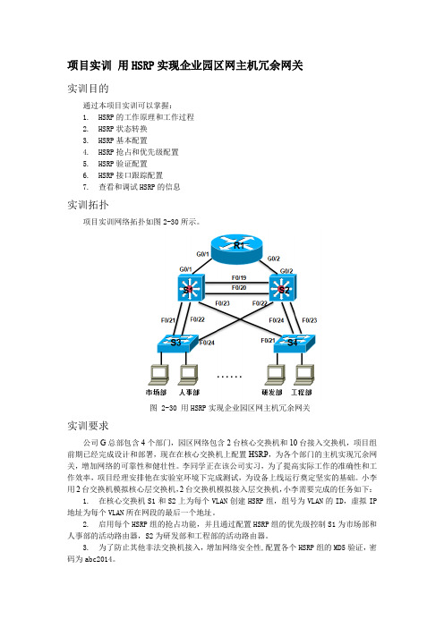
项目实训用HSRP实现企业园区网主机冗余网关实训目的通过本项目实训可以掌握:1.HSRP的工作原理和工作过程2.HSRP状态转换3.HSRP基本配置4.HSRP抢占和优先级配置5.HSRP验证配置6.HSRP接口跟踪配置7.查看和调试HSRP的信息实训拓扑项目实训网络拓扑如图2-30所示。
图 2-30 用HSRP实现企业园区网主机冗余网关实训要求公司G总部包含4个部门,园区网络包含2台核心交换机和10台接入交换机,项目组前期已经完成设计和部署,现在在核心交换机上配置HSRP,为各个部门的主机实现冗余网关,增加网络的可靠性和健壮性。
李同学正在该公司实习,为了提高实际工作的准确性和工作效率,项目经理安排他在实验室环境下完成测试,为设备上线运行奠定坚实的基础。
小李用2台交换机模拟核心层交换机,2台交换机模拟接入层交换机,小李需要完成的任务如下:1.在核心交换机S1和S2上为每个VLAN创建HSRP组,组号为VLAN的ID,虚拟IP 地址为每个VLAN所在网段的最后一个地址。
2.启用每个HSRP组的抢占功能,并且通过配置HSRP组的优先级控制S1为市场部和人事部的活动路由器,S2为研发部和工程部的活动路由器。
3.为了防止其他非法交换机接入,增加网络安全性,配置各个HSRP组的MD5验证,密码为abc2014。
4.为了增强网络可靠性,在S1配置HSRP的接口跟踪,跟踪到R1的上行链路,如果链路失效,确保S2成为活动路由器;在S2配置HSRP的接口跟踪,跟踪到R1的上行链路,如果链路失效,确保S1成为活动路由器。
提示:注意接口跟踪减去优先级的问题。
5.配置园区网各个VLAN内的主机的IP地址和网关,注意网关要配置成各个VLAN所对应的HSRP组的虚拟地址。
6.对以上配置逐项测试成功,最后确保园区网中的所有主机都能通过冗余网关访问到R1。
7.将跟踪的接口关闭,然后再开启,查看HSRP状态的切换以及主机通信的中断时间情况。
HSRP基本实验及其测试
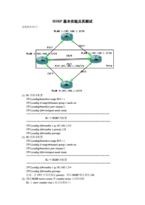
HSRP基本实验及其测试实验拓扑如下:(1)R1的基本配置SW1(config)#interface range f0/0 – 1SW1(config-if-range)#channel-group 1 mode onSW1(config)#interface port-channel 1SW1(config-if)#switchport mode trunk*****************************************************************R1中HSRP的配置****************************************************************** SW1(config-if)#standby 1 ip 192.168.1.254SW1(config-if)#standby 1 priority 120SW1(config-if)#standby preempt(2)R2的基本配置SW1(config)#interface range f0/0 – 1SW1(config-if-range)#channel-group 1 mode onSW1(config)#interface port-channel 1SW1(config-if)#switchport mode trunk*****************************************************************R2中HSRP的配置****************************************************************** SW2(config-if)#standby 1 ip 192.168.1.254SW2(config-if)#standby preempt注意,在SW2中没有指定priority,所以HSRP默认使用100(3)测试HSRP Active router和standby router之间的切换R1上show standby vlan 1显示结果如下:SW1#show standby vlan 1Vlan1 - Group 1State is Active2 state changes, last state change 00:07:18Virtual IP address is 192.168.1.254Active virtual MAC address is 0000.0c07.ac01Local virtual MAC address is 0000.0c07.ac01 (v1 default)Hello time 3 sec, hold time 10 secNext hello sent in 2.752 secsPreemption enabledActive router is localStandby router is 192.168.1.2, priority 100 (expires in 8.916 sec)Priority 120 (configured 120)IP redundancy name is "hsrp-Vl1-1" (default)SW2#show standby vlan 1Vlan1 - Group 1State is Standby1 state change, last state change 00:08:34Virtual IP address is 192.168.1.254Active virtual MAC address is 0000.0c07.ac01Local virtual MAC address is 0000.0c07.ac01 (v1 default)Hello time 3 sec, hold time 10 secNext hello sent in 1.396 secsPreemption enabledActive router is 192.168.1.1, priority 120 (expires in 9.372 sec)Standby router is localPriority 100 (default 100)IP redundancy name is "hsrp-Vl1-1" (default)******************************************************************************* 将SW1和SW3之间的链路中断,观察active router 和standby router的转换******************************************************************************* SW1(config)#interface vlan 1SW1(config-if)#shutdown*Mar 1 00:36:19.947: %HSRP-5-STATECHANGE: Vlan1 Grp 1 state Active -> Init Type escape sequence to abort.Sending 5, 100-byte ICMP Echos to 192.168.1.4, timeout is 2 seconds:!!!!!Success rate is 100 percent (5/5), round-trip min/avg/max = 24/58/84 ms这个结果说明,当avtive router SW1出现故障时,standby router SW2开始运行,而用户的服务不会中断;因为这个时候已经配置了抢占,所以SW2这个时候成了avtive router*Mar 1 00:36:19.747: %HSRP-5-STATECHANGE: Vlan1 Grp 1 state Standby -> Active@@@@@@@@@@@@@@@@@@@@@@@@@@@@@@@@@@@@@@@@@@ SW1(config)#interface vlan 1SW1(config-if)#no shutdown*Mar 1 00:40:14.063: %HSRP-5-STATECHANGE: Vlan1 Grp 1 state Listen -> Active可见,当SW1的故障恢复的时候,它又称为了avtive router,因为配置的时候配置了抢占。
- 1、下载文档前请自行甄别文档内容的完整性,平台不提供额外的编辑、内容补充、找答案等附加服务。
- 2、"仅部分预览"的文档,不可在线预览部分如存在完整性等问题,可反馈申请退款(可完整预览的文档不适用该条件!)。
- 3、如文档侵犯您的权益,请联系客服反馈,我们会尽快为您处理(人工客服工作时间:9:00-18:30)。
实验六-HSRP与上行链路跟踪一、实验目的1、组网要求企业总部局域网采用两台核心交换机组网来提高网络可靠性,为防止二层环路,需要全网运行STP;将SW1部署为跟网桥,SW2部署为备份跟网桥,并将接入PC的接口配置为portfast端口;SW1—SW2之间使用链路捆绑进一步提高可靠性;同时,部署HSRP为内部vlan提供网关冗余。
本局域网有4个vlan,生产业务vlan10,办公业务vlan11,二层交换机网管vlan8;将SW1部署为vlan8/10/11的主网关,将SW2部署为vlan11的主网关;要求vlan10,vlan11的主网关跟踪上行链路。
2、测试HSRP主备网关倒换。
3、分析PC1 ping PC2的三层通信过程和二层通信过程。
二、实验拓扑三、实验内容1、基本信息配置SW1Switch>enable//进入全局模式Switch#config terminal//进入特权模式Switch(config)#hostname SW1//设置主机名SW1(config)#no ip domain lookup //禁用域名查找SW1(config)#enable password ip//设置进入特权模式密码SW1(config)#line console 0//连接到console线口SW1(config-line)#logging synchronous //自动换行SW1(config-line)#exec-t 0//超时为0SW1(config-line)#password ip//设置进入console线口的密码SW1(config-line)#login//进入console线口是需要进行认证SW1(config-line)#exit//退出console线口SW1(config)#line aux 0//进入线口SW1(config-line)#logging synchronous //自动换行SW1(config-line)#exec-t 0//超时为0SW1(config-line)#password bluefox//设置进入本线口的密码SW1(config-line)#login//设置进入线口是进行认证SW1(config-line)#exit//退出线口SW1(config)#line vty 04//进入线口SW1(config-line)#logging synchronous //自动换行SW1(config-line)#exec-t 0//超时为0SW1(config-line)#password bluefox//设置进入密码SW1(config-line)#login//设置进入是进行认证SW1(config-line)#exit//退出线口SW2Switch>enableSwitch#config terminalSwitch(config)#hostname SW2SW2(config)#no ip domain lookup SW2(config)#enable password ipSW2(config)#line console 0SW2(config-line)#logging synchronous SW2(config-line)#exec-t 0SW2(config-line)#password ipSW2(config-line)#loginSW2(config-line)#exitSW2(config)#line aux 0SW2(config-line)#logging synchronous SW2(config-line)#exec-t 0SW2(config-line)#password bluefox SW2(config-line)#loginSW2(config-line)#exitSW2(config)#line vty 04SW2(config-line)#logging synchronous SW2(config-line)#exec-t 0SW2(config-line)#password bluefox SW2(config-line)#loginSW2(config-line)#exitSW3SW3>enableSW3#config terminalSW3(config)#hostname SW3SW3(config)#no ip domain lookup SW3(config)#enable password ipSW3(config)#line console 0SW3(config-line)#logging synchronous SW3(config-line)#exec-t 0SW3(config-line)#password ipSW3(config-line)#loginSW3(config-line)#exitSW3(config)#line aux 0SW3(config-line)#logging synchronous SW3(config-line)#exec-t 0SW3(config-line)#password bluefox SW3(config-line)#loginSW3(config-line)#exitSW3(config)#line vty 04SW3(config-line)#logging synchronous SW3(config-line)#exec-t 0SW3(config-line)#password bluefox SW3(config-line)#loginSW3(config-line)#exitRT5Router>enableRouter#config terminalRouter(config)#hostname RT5RT5(config)#no ip domain lookupRT5(config)#enable password ipRT5(config)#line console 0RT5(config-line)#logging synchronous RT5(config-line)#exec-t 0RT5(config-line)#password ipRT5(config-line)#loginRT5(config-line)#exitRT5(config)#line aux 0RT5(config-line)#logging synchronous RT5(config-line)#exec-t 0RT5(config-line)#password bluefox RT5(config-line)#loginRT5(config-line)#exitRT5(config)#line vty 04RT5(config-line)#logging synchronous RT5(config-line)#exec-t 0RT5(config-line)#password bluefox RT5(config-line)#loginRT5(config-line)#exitRT6Router>enableRouter#config terminalRouter(config)#hostname RT6RT6(config)#no ip domain lookupRT6(config)#enable password ipRT6(config)#line console 0RT6(config-line)#logging synchronous RT6(config-line)#exec-t 0RT6(config-line)#password ipRT6(config-line)#loginRT6(config-line)#exitRT6(config)#line aux 0RT6(config-line)#logging synchronous RT6(config-line)#exec-t 0RT6(config-line)#password bluefox RT6(config-line)#loginRT6(config-line)#exitRT6(config)#line vty 04RT6(config-line)#logging synchronous RT6(config-line)#exec-t 0RT6(config-line)#password bluefox RT6(config-line)#loginRT6(config-line)#exit2、创建vlanSW1SW1#vlan database//进入vlan database模式SW1(vlan)#vlan 8//创建vlan8SW1(vlan)#vlan 10//创建vlan10SW1(vlan)#vlan 11//创建vlan11SW1(vlan)#exit//退出vlan database模式、SW2SW2#vlan database//进入vlan database模式SW2(vlan)#vlan 8//创建vlan8SW2(vlan)#vlan 10//创建vlan10SW2(vlan)#vlan 11//创建vlan11SW2(vlan)#exit//退出vlan database模式SW3SW3#vlan database//进入vlan数据库SW3(vlan)#vlan 8//创建vlan8SW3(vlan)#vlan 10//创建vlan10SW3(vlan)#vlan 11//创建vlan11SW3(vlan)#exit//退出vlan database模式4、跟网桥配置SW1SW1(config)#spanning-tree vlan 8 priority 0//配置sw1为vlan8的跟网桥SW1(config)#spanning-tree vlan 10 priority 0//配置sw1为vlan10的跟网桥SW1(config)#spanning-tree vlan 11 priority 0//配置sw1为vlan11 的跟网桥注:模拟器上不支持批量配置vlan跟网桥,只能一个一个配置SW2SW2(config)#spanning-tree vlan 8 priority 4096 //配置sw2为vlan8的备份网桥SW2(config)#spanning-tree vlan 10 priority 4096//配置sw2为vlan10 的备份网桥SW2(config)#spanning-tree vlan 11 priority 4096//配置sw2为vlan11的备份网桥5、二层链路捆绑SW1SW1(config)#interface range fastEthernet 0/1 -2//进入端口1和2SW1(config-if-range)#switchport trunkencapsulation dot1q//设置trunk封装协议为dot1qSW1(config-if-range)#switchport mode trunk//端口为trunk模式SW1(config-if-range)#switchport trunk allowed vlan all//配置trunk允许所有vlan通过SW1(config-if-range)#channel-group 2 mode on //将端口1和2划分到通道组2中SW1(config-if-range)#exit//退出端口1和2SW2SW2(config)#interface range fastEthernet 0/1 -2 //进入端口1 和2SW2(config-if-range)#switchport trunk encapsulation dot1q//配置trunk封装协议为dot1qSW2(config-if-range)#switchport mode trunk//配置端口为trunk接口SW2(config-if-range)#switchport trunk allowed vlan all//配置trunk允许所有vlan通过SW2(config-if-range)#channel-group 2 mode on //将接口1和2 划分到通道组2中SW2(config-if-range)#exit//退出接口6、二层接口配置SW1SW1(config)#interface fastEthernet 0/3//进入接口SW1(config-if)#switchport trunk encapsulation dot1q//配置trunk封装协议为dot1qSW1(config-if)#switchport mode trunk//配置接口为trunk接口SW1(config-if)#switchport trunk allowed vlan all//配置trunk允许所有vlan通过SW1(config-if)#exit//退出端口SW2SW2(config)#interface fastEthernet 0/3//进入接口SW2(config-if)#switchport trunk encapsulationdot1q//配置trunk封装协议为dot1qSW2(config-if)#switchport mode trunk//配置接口为trunk接口SW2(config-if)#switchport trunk allowed vlan all//配置trunk允许所有vlan通过SW2(config-if)#exit//退出接口SW3SW3(config)#interface fastEthernet 0/10//进入接口SW3(config-if)#switchport mode access//配置接口为access接入模式SW3(config-if)#switchport access vlan 10//将接口划分到vlan10 中SW3(config-if)# spanning-tree portfast//设置接口为portfast模式,SW3(config-if)#exit//退出接口SW3(config)#interface fastEthernet 0/11//进入接口SW3(config-if)#switchport mode access//配置接口为access接入模式SW3(config-if)#switchport access vlan 11//将接口划分到vlan11中SW3(config-if)# spanning-tree portfast//设置接口为portfast模式SW3(config-if)#exit//退出接口SW3(config)#interface range fastEthernet 0/1 -2 //进入接口1和2,此处为批量设置,因为两个接口的配置相同SW3(config-if-range)#switchport trunk encapsulation dot1q//配置trunk的封装协议为dot1qSW3(config-if-range)#switchport mode trunk//配置接口为trunk模式SW3(config-if-range)#switchport trunk allowed vlan all//配置trunk允许所有vlan通过SW3(config-if-range)#exit//退出接口1和27、二层设备网管地址配置SW3(config)#interface vlan 8//为sw3配置网管地址SW3(config-if)#ip address 192.168.8.132 255.255.255.128//配置ip地址SW3(config-if)#no shutdown//启用端口SW3(config-if)#exit//退出8、三层接口配置SW1SW1(config)#interface vlan 8//配置vlan8的路由点SW1(config-if)#ip address 192.168.8.130 255.255.255.128//配置ip地址SW1(config-if)#no shutdown//启用SW1(config-if)#exit//退出SW1(config)#interface vlan 10//配置vlan10的路由点SW1(config-if)#ip address 192.168.10.2 255.255.255.0//配置ip地址SW1(config-if)#no shutdown//启用SW1(config-if)#exit//退出SW1(config)#interface vlan 11//配置vlan11的路由点SW1(config-if)#ip address 192.168.11.2 255.255.255.0//配置ipSW1(config-if)#no shutdown//启用SW1(config-if)#exitSW2SW2(config)#interface vlan 8//配置vlan8的路由点SW2(config-if)#ip address 192.168.8.131 255.255.255.128//配置ip地址SW2(config-if)#no shutdown//启用SW2(config-if)#exit//退出SW2(config)#interface vlan 10//配置vlan10的路由点SW2(config-if)#ip address 192.168.10.3 255.255.255.0//配置ip地址SW2(config-if)#no shutdown//启用SW2(config-if)#exit//退出SW2(config)#interface vlan 11//配置vlan11的路由点SW2(config-if)#ip address 192.168.11.3 255.255.255.0//配置ipSW2(config-if)#no shutdown//启用SW2(config-if)#exitSW1上行链路SW1(config)#interface fastEthernet 0/12//进入接口SW1(config-if)#no switchport//配置接口为三层接口SW1(config-if)#ip address 192.168.9.1 255.255.255.252//为接口配置IP地址SW1(config-if)#no shutdown//打开接口SW1(config-if)#exit//退出接口RT5(config)#interface ethernet 0/0//进入接口RT5(config-if)#ip address 192.168.9.2 255.255.255.252//配置IP地址RT5(config-if)#no shutdown//打开接口RT5(config-if)#exitSW2上行链路SW2(config)#interface fastEthernet 0/12//进入接口SW2(config-if)#no switchport//配置接口为三层接口SW2(config-if)#ip address 192.168.9.5 255.255.255.252//配置IP地址SW2(config-if)#no shutdown//打开接口SW2(config-if)#exit//退出接口RT6(config)#interface ethernet 0/0//进入接口RT6(config-if)#ip address 192.168.9.6 255.255.255.252//配置IP地址RT6(config-if)#no shutdown//打开端口RT6(config-if)#exit9、HSRP部署SW1上的HSRP配置SW1(config)#interface vlan 8SW1(config-if)#standby 8 ip 192.168.8.129//配置HSRP组8的虚IPSW1(config-if)#standby 8 priority 120//设置组8 的优先级SW1(config-if)#standby 8 preempt//配置组8的抢占SW1(config-if)#exitSW1(config)#interface vlan 10SW1(config-if)#standby 10 ip 192.168.10.1//配置组10 的虚IPSW1(config-if)#standby 10 priority 120//配置组10的优先级SW1(config-if)#standby 10 preempt配置组10的抢占SW1(config-if)#standby 10 track fastethernet 0/12 30//配置HSRP组10跟踪上连接口,上连接口DOWN时优先级减30SW1(config-if)#exitSW1(config)#interface vlan 11SW1(config-if)#standby 11 ip 192.168.11.1 //配置组11的虚IPSW1(config-if)#standby 11 preempt//配置组11的抢占SW1(config-if)#exitSW2上HSRP的配置SW2(config)#interface vlan 8SW2(config-if)#standby 8 ip 192.168.8.129 //配置组8的虚IPSW2(config-if)#standby 8 preempt//配置组8的抢占SW2(config-if)#exitSW2(config)#interface vlan 10SW2(config-if)#standby 10 ip 192.168.10.1 //配置组10的虚IPSW2(config-if)#standby 10 preempt//配置10的抢占SW2(config-if)#exitSW2(config)#interface vlan 11SW2(config-if)#standby 11 ip 192.168.11.1//配置组11的虚IPSW2(config-if)#standby 11 priority 120//配置组11的优先级SW2(config-if)#standby 11 preempt//配置组11的抢占SW2(config-if)#standby 11 track fastethernet 0/12 30//配置组11跟踪上连接口,上连接口down时优先级减30SW2(config-if)#exit注:不配置优先级时默认是10010、开启三层交换路由功能SW1(config)#ip routingSW2(config)#ip routing11、静态路由SW1(config)#ip route 192.168.9.4 255.255.255.252 192.168.10.3SW2(config)#ip route 192.168.9.0 255.255.255.252 192.168.10.2RT5(config)#ip route 0.0.0.0 0.0.0.0 192.168.9.1 RT6(config)#ip route 0.0.0.0 0.0.0.0 192.168.9.5 四、实验结果SW1#show standby briefP indicates configured to preempt.Interface Grp Prio P State Active Standby Virtual IPVl8 8 120 P Active local 192.168.8.131 192.168.8.129Vl10 10 120 P Active local 192.168.10.3 192.168.10.1Vl11 11 100 P Standby 192.168.11.3 local 192.168.11.1SW2#show standby briefP indicates configured to preempt.Interface Grp Prio P State Active Standby Virtual IPVl8 8 100 P Standby 192.168.8.130 local 192.168.8.129 Vl10 10 100 Standby 192.168.10.2 local 192.168.10.1 Vl11 11 120 P Active local 192.168.11.2 192.168.11.1Show running-config信息截取SW1interface Vlan8ip address 192.168.8.130 255.255.255.128 standby 8 ip 192.168.8.129standby 8 priority 120standby 8 preempt!interface Vlan10ip address 192.168.10.2 255.255.255.0standby 10 ip 192.168.10.1standby 10 priority 120standby 10 preempt!interface Vlan11ip address 192.168.11.2 255.255.255.0 standby 11 ip 192.168.11.1standby 11 preempt!SW2interface Vlan8ip address 192.168.8.131 255.255.255.128 standby 8 ip 192.168.8.129standby 8 preempt!interface Vlan10ip address 192.168.10.3 255.255.255.0 standby 10 ip 192.168.10.1standby 10 preempt!interface Vlan11ip address 192.168.11.3 255.255.255.0 standby 11 ip 192.168.11.1standby 11 priority 120standby 11 preempt全网连通性测试PC1VPCS 1 >ping 192.168.8.132192.168.8.132 icmp_seq=1 timeout192.168.8.132 icmp_seq=2 time=35.000 ms 192.168.8.132 icmp_seq=3 time=44.000 ms 192.168.8.132 icmp_seq=4 time=13.000 ms 192.168.8.132 icmp_seq=5 time=49.000 msVPCS 1 >ping 192.168.11.100192.168.11.100 icmp_seq=1 time=11.000 ms 192.168.11.100 icmp_seq=2 time=10.000 ms 192.168.11.100 icmp_seq=3 time=45.000 ms 192.168.11.100 icmp_seq=4 time=10.000 ms 192.168.11.100 icmp_seq=5 time=10.000 msVPCS 1 >ping 192.168.9.2192.168.9.2 icmp_seq=1 time=51.000 ms 192.168.9.2 icmp_seq=2 time=14.000 ms 192.168.9.2 icmp_seq=3 time=21.000 ms192.168.9.2 icmp_seq=5 time=13.000 msVPCS 1 >ping 192.168.9.6192.168.9.6 icmp_seq=1 time=59.000 ms 192.168.9.6 icmp_seq=2 time=12.000 ms 192.168.9.6 icmp_seq=3 time=17.000 ms 192.168.9.6 icmp_seq=4 time=15.000 ms 192.168.9.6 icmp_seq=5 time=19.000 ms PC2VPCS 2 >ping 192.168.10.100192.168.10.100 icmp_seq=1 timeout192.168.10.100 icmp_seq=2 time=14.000 ms 192.168.10.100 icmp_seq=3 time=11.000 ms 192.168.10.100 icmp_seq=4 time=10.000 ms 192.168.10.100 icmp_seq=5 time=46.000 msVPCS 2 >ping 192.168.8.132192.168.8.132 icmp_seq=1 timeout192.168.8.132 icmp_seq=2 timeout192.168.8.132 icmp_seq=3 timeout192.168.8.132 icmp_seq=4 time=21.000 msVPCS 2 >ping 192.168.8.132192.168.8.132 icmp_seq=1 time=28.000 ms 192.168.8.132 icmp_seq=2 time=10.000 ms 192.168.8.132 icmp_seq=3 time=14.000 ms 192.168.8.132 icmp_seq=4 time=9.000 ms 192.168.8.132 icmp_seq=5 time=44.000 msVPCS 2 >ping 192.168.9.6192.168.9.6 icmp_seq=1 timeout192.168.9.6 icmp_seq=2 time=31.000 ms 192.168.9.6 icmp_seq=3 time=18.000 ms 192.168.9.6 icmp_seq=4 time=16.000 ms 192.168.9.6 icmp_seq=5 time=18.000 msVPCS 2 >ping 192.168.9.2192.168.9.2 icmp_seq=1 timeout192.168.9.2 icmp_seq=2 timeout192.168.9.2 icmp_seq=3 time=22.000 ms 192.168.9.2 icmp_seq=4 time=21.000 ms 192.168.9.2 icmp_seq=5 time=88.000 msHSRP主备切换测试将SW1上的fa0/12shutdown后SW1#show standby briefP indicates configured to preempt.|Interface Grp Prio P State Active Standby Virtual IPVl8 8 120 P Active local 192.168.8.131 192.168.8.129Vl10 10 90 P Standby 192.168.10.3 local 192.168.10.1 Vl11 11 100 P Standby 192.168.11.3 local 192.168.11.1SW2#show standby briefP indicates configured to preempt.|Interface Grp Prio P State Active Standby Virtual IPVl8 8 100 P Standby192.168.8.130 local 192.168.8.129 Vl10 10 100 P Active local 192.168.10.2 192.168.10.1Vl11 11 120 P Active local 192.168.11.2 192.168.11.1将SW2上的fa0/12shutdown后SW1#show standby briefP indicates configured to preempt.|Interface Grp Prio P State Active Standby Virtual IPVl8 8 120 P Active local 192.168.8.131 192.168.8.129Vl10 10 120 P Active local 192.168.10.3 192.168.10.1Vl11 11 100 P Active local 192.168.11.3 192.168.11.1SW2#show standby briefP indicates configuredto preempt.|Interface Grp Prio P State Active Standby Virtual IPVl8 8 100 P Standby 192.168.8.130 local 192.168.8.129 Vl10 10 100 P Standby 192.168.10.2 local 192.168.10.1 Vl11 11 90 P Standby 192.168.11.2 local 192.168.11.1 五、实验分析与心得简单分析PC1 ping PC2的通信过程:1、PC1发送数据给网关SW1,因为它是vlan10 的主网关,SW3收到数据后,查MAC地址表从fa0/1端口发送出去;2、SW1收到数据后,解封装,发现MAC地址是自己,但是目的ip不是自己,查路由表,重新封装数据,从fa0/3端口发送出去;3、SW3收到数据帧后,查MAC地址表,从fa0/11端口发送出去。