油水孔板波纹分离填料产品介绍
规整填料企业标准

SLB -125X SLB -125Y
125
SLB -250X SLB -250Y
250
SLB -350X SLB -350Y
350
24
±0.6
39
±1.0
11.6
±0.5
21
±0.8
8.5
±0.4
13.8
±0.6
30
±2
45
±2
倾角,°
基本尺寸
30 45 30 45 30 45 30 45 30 45 30 45
5.2 规整填料用材料应附有生产厂的材料质量证明书。 6 单片填料制造、检验要求 6.1 单片填料基本参数 6.1.1 金属孔板波纹填料应符合表 2 的规定。
表 2 金属孔板波纹填料基本参数
项
目
型号
公称比表
面积
m2/m3
峰高,mm 基本尺寸 允许偏差
峰距,mm 基本尺寸 允许偏差
倾角,° 基本尺寸 允许偏差
≤700
D0-7
±3
>3000
D0-20 模拟圈试装
7
7.2.3 填料盘(块)的松紧度:填料盘(块)上箍、点焊、捆扎、打穿钉时,要保证填料
盘(块)结实、牢固,且松紧度合适。
7.2.4 填料盘(块)的平整度:平整度的要求见表 12。
表 12 填料盘平整度要求
填料比表面积 A,m2/m3
ZPB -250Y
250
11.9
±0.5
23.8
±0.5
ZPB -350X
ZPB -350Y
350
8.6
±0.5
16.2
±0.5
6.1.8 麦勒派克金属孔板波纹填料应符合表 9 的规定。
规整填料企业标准
塔内径 D0,
盘径,
mm
mm
mm
mm
mm
≤100
D0-3
-1
≤800
D0-8
盘径偏差, mm ±3
≤200
D0-3
±1
>800~1100
D0-10
±4
≤400
D0-4
±2
>1100~1600
D0-11
±5
≤500
D0-5
±2
>1600~2000 D0-15 模拟圈试装
≤600
D0-6
±3
>2000~3000 D0-18 模拟圈试装
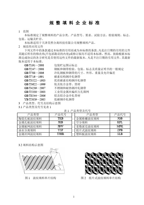
图 3 波纹填料截面图单片结构
图 4 组片式波纹填料截面图
图 5 峰谷搭片式波纹填料
图 6 峰谷搭片式波纹填料截面图
图 7 填料盘结构
4 产品型号 4.1 符号 4.1.1 填料的比表面积用阿拉伯数字表示,单位为 m2/m3 表示。 4.1.2 波纹倾角的符号 X、Y X、Y—填料波纹棱边与垂线之间的夹角,X—代表 30°,Y—代表 45°。 4.2 产品型号
5.2 规整填料用材料应附有生产厂的材料质量证明书。 6 单片填料制造、检验要求 6.1 单片填料基本参数 6.1.1 金属孔板波纹填料应符合表 2 的规定。
表 2 金属孔板波纹填料基本参数
项
目
型号
公称比表
面积
m2/m3
峰高,mm 基本尺寸 允许偏差
峰距,mm 基本尺寸 允许偏差
倾角,° 基本尺寸 允许偏差
ZPB -100X
ZPB -100Y
100
31.8
±1.0
51.5
±1.0
ZPB -125X 125
油水分离填料性能介绍
商品描述:
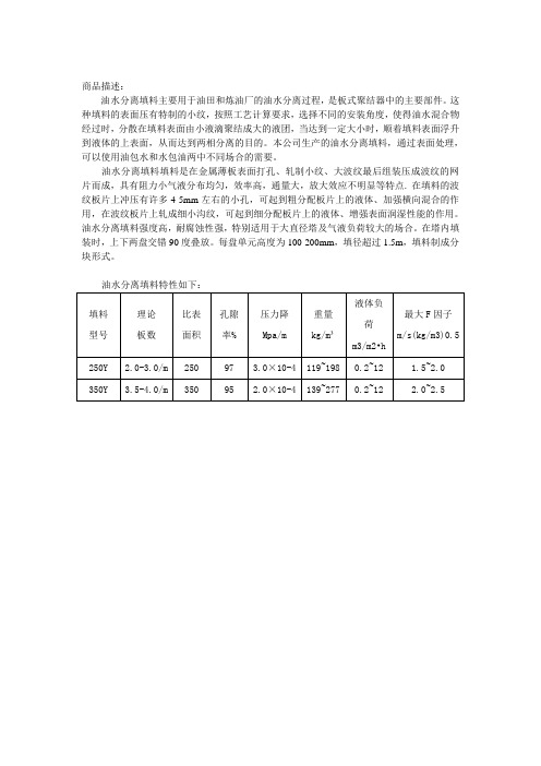
油水分离填料主要用于油田和炼油厂的油水分离过程,是板式聚结器中的主要部件。
这种填料的表面压有特制的小纹,按照工艺计算要求,选择不同的安装角度,使得油水混合物经过时,分散在填料表面由小液滴聚结成大的液团,当达到一定大小时,顺着填料表面浮升到液体的上表面,从而达到两相分离的目的。
本公司生产的油水分离填料,通过表面处理,可以使用油包水和水包油两中不同场合的需要。
油水分离填料填料是在金属薄板表面打孔、轧制小纹、大波纹最后组装压成波纹的网片而成,具有阻力小气液分布均匀,效率高,通量大,放大效应不明显等特点. 在填料的波纹板片上冲压有许多4-5mm左右的小孔,可起到粗分配板片上的液体、加强横向混合的作用,在波纹板片上轧成细小沟纹,可起到细分配板片上的液体、增强表面润湿性能的作用。
油水分离填料强度高,耐腐蚀性强,特别适用于大直径塔及气液负荷较大的场合。
在塔内填装时,上下两盘交错90度叠放。
每盘单元高度为100-200mm,填径超过1.5m,填料制成分块形式。
油水分离填料特性如下:。
斜通道波纹板油水分离器技术说明
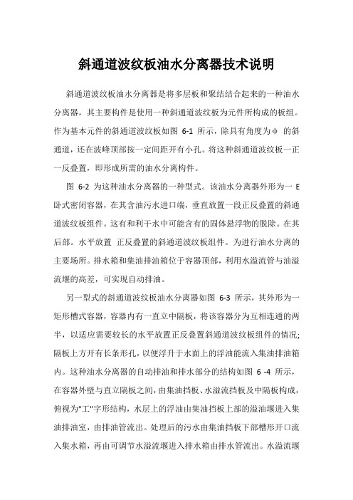
斜通道波纹板油水分离器技术说明斜通道波纹板油水分离器是将多层板和聚结结合起来的一种油水分离器,其主要构件是使用一种斜通道波纹板为元件所构成的板组。
作为基本元件的斜通道波纹板如图6-1 所示,除具有角度为φ的斜通道,还在波峰顶部按一定间距开有小孔。
将这种斜通道波纹板一正一反叠置,即形成所需的油水分离构件。
图6-2 为这种油水分离器的一种型式。
该油水分离器外形为一E 卧式密闭容器,在其含油污水进口端,垂直放置一段正反叠置的斜通道波纹板组件。
这有和利干水中可能含有的固体悬浮物的脱除。
在其后部。
水平放置正反叠置的斜通道波纹板组件。
为进行油水分离的主要场所。
排水箱和集油排油箱位于容器顶部,利用水溢流管与油溢流堰的高差,可实现自动排油。
另一型式的斜通道波纹板油水分离器如图6-3 所示,其外形为一矩形槽式容器,容器内有一直立中隔板,将该容器分为互相连通的两半,以适应需要较长的水平放置正反叠置斜通道波纹板组件的情况;隔板上方开有长条形孔,以便浮升于水面上的浮油能流入集油排油箱内。
这种油水分离器的自动排油和排水部分的结构如图 6 -4 所示,在容器外壁与直立隔板之间,由集油挡板、水溢流挡板及中隔板构成,俯视为"工"字形结构,水层上的浮油由集油挡板上部的溢油堰进入集油排油室,由排油管流出。
处理后的污水由集油挡板下部槽形开口流入集水箱,再由可调节水溢流堰进入排水箱由排水管流出。
水溢流堰底部连一排空管,以便停工时排出油水分离器内的存水。
如果要求的板组不是太长,或空间条件许可,也可不设置中间直立中隔板,形成水流直通式配置。
斜通道波纹板可用金属板材、塑料板材或玻璃纤维增强树脂制作。
斜通道波纹板也可作成如图6-5 所示的双波纹型式,这既有利于水中分散油滴的粘附聚结,又会增强波纹板的刚性。
表6-1为斜通道波纹板几何参数的一般范围。
表6-1 斜通道波纹板几何参数斜通道波纹板油水分离器用于含油污水处理除油过程,有如下特点∶(1)脱油效率高从工业使用的大量操作数据看,脱油效率均在90% 以上。
不锈钢孔板波纹填料

5.1.3根据使用单位所需型号,按标准要求正在的压制孔板波纹片
5.1.4根据塔设备设计确定填料盘可以做成整盘式或分块式,分块的 目的是便于填料的安装,每个分块尺寸应能从人孔进入塔内组装, 对于塔径小于800mm的塔可按整盘制造,也可分块制造。 图片上是我们正在生产的Ф 3200,350Y的分块式填料。
70#
70×35.5×0.6
4250
118
55
4、材料 4.1选用材料应按GB 3280中规定的技术要求执行。 4.2选用不锈钢板和钢带的尺寸、外形、重量及允许偏差应 按GB 708规定中的B级精度执行。 4.3选用材料应有质量检验证明书、合格证、化验单,并定 期作抽样检验,无以上证书的材料应进行质量分析检验。 5、检验及验收 5.1填料应分批验收,一种尺寸的填料可作为一批。 5.2每批填料中抽样检测的样品量不得少于60个。 5.3样品的外观尺寸如有超过抽样量的5%的数量不符合本标 准要求,帽应从同批产品中加倍抽样数量,重新测试。重 复试验的结果同样适用于该批产品。如果重新测试样品的 不合格率仍大于5%抽样量,则该批产品为不合格。
Fiber Glass Systems LP(FGS)油 水分离器产品介绍说明书

Oil / Water Separators and InterceptorsOil drippings and spills from parking lots, driveways, oil terminals and other vehicular traffic surfaces are being washed into our water supplies by rainwater, creating serious environmental concerns. Fiber Glass Systems LP (FGS) provides a full range of dependable products for the oil/water separator industry.FGS separators are constructed to remove hydrocarbons with a specific gravity up to 0.95 through the use of an enhanced oleophilic coalescer pack system. Oil/water separator designs vary based on required effluent quality and flow rates. An effluent quality of 10 parts per million (10ppm) is typical but the difference between continuous flow and intermittent flow will drastically alter the coalescer pack sequence. Additionally, the concentrations and types of contaminants determines the allowable flow rate through the system. Since these detergents may adversely affect the performance of oil/water separators, quick break detergents must be used if applicable. For more information on various flow applications and applicable products, please contact your sales representative.Our underground separators utilize the same fiberglass manufacturing technology the petroleum industry relies onfor environmental protection. The inherently non-corrosive properties of fiberglass provide the most compatible optionfor your separator application, built by one of the most trusted brands in the world. Our fiberglass separators are buried andfilled with water. Each separator includes a combination ofbaffles and coalescer packs, based on effluent requirements, to accelerate separation. Waste water enters through the inlet and gravity naturally settles heavier solids to the bottom of the tankas the oil floats to the top of the water level. The oily water then passes through the coalescing plates in a straight flow or crossflow direction depending on the tank model. The configurationof the packs efficiently coalesces or joins oil droplets together forming larger masses of oil that rise to the surface whereit accumulates and can be removed. Gravity displacement discharges the effluent though the outlet at a lower point in the tank chamber. Separator systems can also be equipped withdrop boxes, electronic monitoring with high oil level alarmsand control panels, and oil stop valves.Performance claims• Fiberglass construction providescorrosion resistance without coatingsor protection systems.• Enhanced coalescer system is comprisedof oleophilic plates to maximizeseparation and minimize maintenance.• Removable plates simplifiesroutine cleaning.• All tanks are built to the stringentperformance requirements of UL 1316.• Removes free floating oils and settleablesolids for oil/water mixtures to achieve10ppm effluent quality (or 15 ppmif specified).Containment Solutions™ Underground Fiberglass Oil/Water Separators****************3/fgs Design and SizingApplication: Rainwater RunoffOil drippings and spills from parking lots, driveways, oil terminals and other vehicular traffic surfaces are being washed into our water supplies by rainwater, creating serious environmental concerns. Our Oil/Water Separators are designed to meet EPA guidelines for rainwater runoff control.Since each site is unique, the most effective approach is to analyze each situation and design the system accordingly. Our engineering staff can help determine the best fit for your technical considerations and site specific needs. The major design parameters include:• Inlet flow rates• Oil spill capacity• Inlet/outlet concentration • Oil storage capacity • Effluent quality • Temperature• Specific gravity of contaminantsOur UL 2215 separators are sized primarily on flow rates. A complete list of flow rate plate pack options are available, contact your sales representative for more information.InterceptorsIn addition to separators, interceptors are available in single, double, and triple compartment designs. Interceptors reduce sand, settleable materials, and oil or grease prior to sewer discharge. Our interceptors can be used as stand alone units or as the initial stage of a more efficient treatment system utilizing our oil/water separators.Electronics / AccessoriesOil/Water Separator monitoring and control systems can be configured to satisfy a wide range of customer requirements. Control panels, sensors, probes and gauges are available for double-wall and single-wall oil/water separator systems as well as for single-tank or multiple-tank installations. We carry a full line of pump controls, inlet and outlet pumps, and waste oil pumps. Let us package the right model with the proper electronics so when the tank arrives the only thing left to do is connect the piping.****************Underground OWS FeaturesA. Double-Wall SeparatorB. FRP Manway ExtensionC. Oil Draw PipeD. Hydrostatic ReservoirE. Tank SumpF. Cross flow BaffleG. Coalescer Plate PacksH. Oil Stop ValveI. Anchor StrapsJ.Deadman Anchor System4 f t . D i a .55055110440 4 in.9 ft. 8 in.9 ft. 9 in.4259001,000100200800 4 in.11 ft.11 ft. 1 in.5001,0501,5001503001,200 4 in.16 ft. 10 in.16 ft. 11 in.7501,2756 f t . D i a .2,0002004001,600 6 in.13 ft. 10 in.13 ft. 8 in.1,0002,2753,0003006002,400 6 in.16 ft.16 ft. 9 in.1,0752,7504,0004008003,200 6 in.19 ft. 8 in.19 ft. 9 in.1,4752,9755,0005001,0004,0008 in.24 ft. 8 in.25 ft.1,8003,4756,0006001,2004,8008 in.29 ft. 6 in.30 ft. 3 in.2,1003,9008 f t . D i a .6,0006001,2004,8008 in.19 ft. 5 in.19 ft. 6 in.2,3004,2007,0007001,4005,6008 in.22 ft. 2 in.23 ft. 7 in.2,6504,6758,0008001,6006,40010 in.24 ft. 11 in.26 ft. 4 in.2,9505,0759,0009001,8007,20010 in.27 ft. 8 in.27 ft. 9 in.3,3005,45010,0001,0002,0008,00010 in.30 ft. 5 in.30 ft. 6 in.3,5505,95012,0001,2002,4009,60010 in.35 ft. 11 in.36 ft.4,3757,00015,0001,5003,00012,00012 in.44 ft. 5 in.44 ft. 6 in.5,3508,65010 f t . D i a .20,0002,0004,00016,00014 in.37 ft. 8 in.37 ft. 9 in.6,95011,90025,0002,5005,00020,00016 in.45 ft. 11 in.46 ft. 8,30013,90030,0003,0006,00024,00016 in.54 ft. 2 in.54 ft. 3 in.9,60016,30040,0004,0008,00032,00020 in.71 ft. 3 in.71 ft. 4 in.12,65020,975Corrugated plate packs coalesce, or join, oil droplets togetherforming larger masses of oil which rise to the surface.5/fgs Oleophilic coalescer plate packs are intended to be removed for cleaning. The number of plate packs will vary based on tank size and required effluent quality.ABCDEF GHIJ*****************Emergency oil spill capacity is 90% of tank volume based on no accumulated oil in vessel at time of spillAOWS-252525090245 2 in. / 3 in. 6 ft. 1 in. x 2 ft. 1 in. x 3 ft. 5 in.7751,400AOWS-5050500120450 4 in. / 4 in.7 ft. 7 in. x 3 ft. 1 in. x 3 ft. 4 in.1,2252,125AOWS-7575750170705 4 in. / 4 in.10 ft. 1 in. x 3 ft. 7 in. x 3 ft. 4 in.2,1003,350AOWS-1001001,0002401,035 6 in. / 6 in.11 ft. 1 in. x 3 ft. 7 in. x 4 ft. 4 in.2,6754,475AOWS-2002002,0003601,8008 in. / 8 in.16 ft. 9 in. x 4 ft. 1 in. x 4 ft. 4 in.4,2007,025AOWS-2502502,5005002,2508 in. / 8 in.17 ft. 1 in. x 5 ft. 1 in. x 4 ft. 4 in.4,4758,025MOP-101010040901 in. / 1 in.5 ft. 4 in. x 1 ft. 5 in. x 2 ft. 4 in.590925Aboveground Steel SeparatorsOur aboveground Oil/Water Separators combine a unique rectangular steel tank design with state-of-the-art coalescertechnology to provide flow rates comparable to larger units. These systems are designed to separate free oils and settleable solids from rainwater runoff and washdown applications via gravity or pumped flow for intermittent, variable, or first flush flows of oil, water, or a combination of non-emulsified oil/water. Systems are installed either at grade or below grade (within a vault) and feature 10ppm effluent discharge, low maintenance and the superior quality you expect from a Fiber Glass System product.Our separators consist of three processing chambers:1) Primary “Oil and Sediment” Separation Chamber; 2) Secondary “Enhanced Coalescer” Separation Chamber, and 3) Effluent Discharge Chamber. These chambers allow maximum sediment and oil separation, increase retention time and increase surface area for oil separation. Additional features include a unique inlet/outlet design that minimizes external piping, support feet for convenient off-loading, and a removable top making coalescer units and debris plates accessible. The removable coalescer units are constructed of non-metallic oleophilic materials for enhanced performance.All Fiber Glass Systems LP aboveground Oil/Water Separators are designed and tested in accordance with the following criteria:• U.S. Coast Guard Test Method 46 CFR 162.050• Stokes’ Law• API Bulletins No. 421 & 1630 (first edition)• The API Manual on Disposal of Refinery Wastes • EPA Test Method 413.1 & 413.2• UL 1427/fgs Rectangular Design, by DesignSpace-saving design and ease of installation, for an economical solution to above ground storage and treatment. Separators come in single-wall and double-wall tank designs. The all steel construction includes a special interior lining for an extended life and an exterior epoxy coating. An optional elastomeric polyurethane (EMPT) exterior coating is also available.Aboveground OWS FeaturesA. Double-Wall Steel TankB. Enhanced Coalescer Filtering SystemC. Removable Cover w/FittingsD. Optional Electronic Monitoring SystemE. Optional Inlet/Outlet PumpsF. Effluent OutletG. Waste Oil Level SensorH. VentI. Oil Removal FittingBC DEFGHIAFiber Glass Systems17115 San Pedro Ave., Suite 200 San Antonio, Texas 78232 USA Conroe Office500 Conroe Park West Drive Conroe, Texas 77303 USANOV Inc. has produced this brochure for general informationonly, and it is not intended for design purposes. Althoughevery effort has been made to maintain the accuracy andreliability of its contents, NOV Inc. in no way assumesresponsibility for liability for any loss, damage or injuryresulting from the use of information and data herein. Allapplications for the material described are at the user’s riskand are the user’s responsibility.© 2022 NOV Inc. All rights reserved.JIRA 16613/fgs****************。
ASPEN填料类型

ASPEN填料类型BERL BERL Saddle d尔鞍环;BX Sulzer BX苏尔寿BX型板波纹规整填料CMR: Cascade mini-ring聚丙烯阶梯环;COIL COIL Pacl环形填料CROSSFLGRDRaschig Cross-Flow-Grid Structured PackCY:苏尔寿CY (丝网)型规整填料DIXON: DIXON Packing狄克松填料(B环填料)FLEXERAMIC Koch Flexeramic Structured Packin©可赫曲线规整填料FLEXIGRID Koch Flexigrid Structured Packing柯赫格栅规整填料FLEXIMAX Koch Fleximax High Performa nee Ra ndom Packin柯赫高性能散堆填料FLEXIPAC Koch Flexipac Corrugated Sheet Structured Packin柯赫柔性波纹板填料FLEXIRING Koch Flexiring Single-tab Slotted Ring Random Packin柯赫单面环槽不规整填料FLEXISADDL Koch Flexisaddle Ra ndom Pack in柯赫鞍形不规整填料GOODLOE Glitsch Goodloe Structured Packi ng格里奇古德洛卷带型规整填料GRID Glitsch Grid Structured Packi ng格里奇格栅规整填料GRID-PACK Grid Type Structured Packing格栅规整填料HCKP Koch HCKP Multi-tab Slotted Ring Ra ndom Packin柯赫多面槽环形不规整填料HELI Heli Pack螺旋填料HELIX 螺旋角填料HYPAKI-BALL I-Ball Packi ng 球型填料IMTP :In talox Metal Tower Packi ng英特洛克斯金属矩鞍环填料INTX: Intalox Saddle矩鞍环填料ISP Norton Intalox Structured Packing诺顿规整填料KERAPAK Sulzer Kerapak Structured Packin苏尔寿陶瓷板波纹填料(凯勒派克)LESCHIG Leschig Ring浸环MCMAHON: Mcmahon Packing鞍形网填料MELLAPAK Sulzer Mellapak Structured Packing苏尔寿孔板波纹填料MESH: Mesh Ring Packing筛网环形填料PALL Pall Ring鲍尔环RALU-FLOW:Raschig Ralu-FlowRALU-PAK Raschig Ralu-Pa拉西带缝板波填料RALU-RING Raschig Ralu-Rin拉西Ralu环RASCHIG Raschig Ring拉西环SHEET-PACKSheet Type Structured PackingSIGMA:Sigma PackingSNOWFLAKE Intalox Snowflake Plastic PackingSTORUSSDDLRaschig Super-Torus-SaddleSUPER-INTX Super Intalox SaddleSUPER-PAKRashig Super-PakSUPER-RINGRashig Super-RingTORUSSADDLRaschig Torus Saddle WIRE-PACKWire Type Structured Packing。
不锈钢丝网波纹填料盘标准

不锈钢丝网波纹填料盘标准
不锈钢丝网波纹填料盘是一种高性能的压力检测填料盘。
它利用スス技术加工把不锈
钢丝绳筛制成波纹,再将此构形的不锈钢丝绳成多环填充到填料盘内,使填料盘的表面凹
凸不平,提高了密密麻麻的不锈钢丝绳的抗拉性和抗压性。
不锈钢丝网波纹填料盘的表面
经过喷涂处理后,使之具有抗腐蚀性能,能够有效防止腐蚀、结垢,并且在温度范围内具
有良好的使用寿命,确保系统运行平稳、可靠,提高工业安全性。
不锈钢丝网波纹填料盘具有重量轻、强度高、静密填充、小体积占用等特点,满足安
装要求,采用规范技术设计和安全技术设计,材料实用性好,并具有优良的耐磨性能和防
止腐蚀性能。
作为高压\低压填料盘的一种产品,不锈钢丝网波纹填料盘的性价比非常高,具有很强的价值利用率,采用钢铁结合系统抗压性能更有保证,安装容易,拆卸方便,不
易损坏,是一种很好的填料盘产品,被广泛应用在工业循环水系统中。
不锈钢丝网波纹填料盘到质量要求为国家标准GB50243—2002【压力管道给排水工程
施工及验收规范】中有明确规定:密密麻麻的不锈钢丝绳,每米轴料搭重不少于27公斤,抗拉性不少于900公斤,抗压性不少于1250公斤,抗腐蚀性能不少于24小时,硬度不小
于 6.0以上。
不锈钢丝网波纹填料盘可以满足工厂设备运行、发电系统运行、工业水源系统运行等
可见不可见的给排水系统对防止水泥系统结垢、水泥系统腐蚀的严格要求,提高系统可靠性,有效降低运行费用。
- 1、下载文档前请自行甄别文档内容的完整性,平台不提供额外的编辑、内容补充、找答案等附加服务。
- 2、"仅部分预览"的文档,不可在线预览部分如存在完整性等问题,可反馈申请退款(可完整预览的文档不适用该条件!)。
- 3、如文档侵犯您的权益,请联系客服反馈,我们会尽快为您处理(人工客服工作时间:9:00-18:30)。
商品描述:
油水分离填料主要用于油田和炼油厂的油水分离过程,是板式聚结器中的主要部件。
这种填料的表面压有特制的小纹,按照工艺计算要求,选择不同的安装角度,使得油水混合物经过时,分散在填料表面由小液滴聚结成大的液团,当达到一定大小时,顺着填料表面浮升到液体的上表面,从而达到两相分离的目的。
本公司生产的油水分离填料,通过表面处理,可以使用油包水和水包油两中不同场合的需要。
油水分离填料填料是在金属薄板表面打孔、轧制小纹、大波纹最后组装压成波纹的网片而成,具有阻力小气液分布均匀,效率高,通量大,放大效应不明显等特点. 在填料的波纹板片上冲压有许多4-5mm左右的小孔,可起到粗分配板片上的液体、加强横向混合的作用,在波纹板片上轧成细小沟纹,可起到细分配板片上的液体、增强表面润湿性能的作用。
油水分离填料强度高,耐腐蚀性强,特别适用于大直径塔及气液负荷较大的场合。
在塔内填装时,上下两盘交错90度叠放。
每盘单元高度为100-200mm,填径超过1.5m,填料制成分块形式。
油水分离填料特性如下:。