Physical modeling and numerical simulation of elec
基于河湖健康评估技术导则的公信河健康状况评估
第05期(总第468期)吉林水利2021年5月[文章编号]1009—2846(2021)05—0004—04基于河湖健康评估技术导则的公信河健康状况评估徐雅俊(安徽省安庆水文水资源局,安徽安庆246000)[摘要]基于河湖健康评估技术导则,构建的公信河健康评GQ标体系,对公信河流域水文水资源完整性、化学完整性、生物完整性、社会服务功能完整性e及河流总体健康状况进行评估$Q出公信河健康存在的问题,为流域的健康持续发展提供技术支撑$[关键词]河流健康;Q标体系;公信河流域[中图分类号]P228.4河湖健康是指河湖自然生态状况良好,同时具有可持续的社会服务功能$自然生态状况包括河湖的物理、化学和生态三个方面,用完整性来表述其良好状态;可持续的社会服务功能是指河湖不仅具有良好的自然生态状况,而且具有可以持续为人类社会提供服务的能力$随着经济社会的发展以及人类对河湖的不合理开发利用,河湖健康问题频发,河湖健康越来越引发人们的关注叫为掌握我国河湖健康状况,我国于2010年左右开启了河湖健康的,经过近十年的经总,2020年利部发布《河湖健康评估技术导则》指导各地好河湖健康评$河湖健康问题,“”,河湖健康评估为有的理具,地方好河理,健康持续发展$1评估对象公信河位于池州市石台县,皖南山区腹部,为我国右河的头支流,面积369km2$河主河道长46.4km,发源于仙寓山,流经、,汇牯牛降、竹溪、利、、、、、河,,河汇合$河面10km2以上的小支[文献标识码]B流有15个,沿线建有小(2"型水库5个。
流域开发利用,为地,功能为功能区-保留区,面状为!类,理为!类叫2公信河健康评估体系构建2.1指标体系根据公信河现状,按照评估导则进行评价,评价体系包括层(河流健康状况)、准则层和指标层3级体系$其中准则层包括水文资源完整性、物理构完整性、完整性、生物完整性和社会服务功能完整性5个方面$指标层根据i 河的特进行指筛选,为数据获取不易舍弃底泥污染状况1个备选指标,最终确定公信河河流健康评估的指标体系为16个指,其中基本指标10个,备选指6个。
伯努利方程教学实验与数值仿真应用

实验教学形式和测量技术的发展趋于多样化, 计算机技术在力学实验教学中的作用日益重 要[3, 6-8] 。 基于管流稳定总流伯努利方程教学实验, 李占松[3] 等和商树桓[7] 等分别用 VB 和 QBasic 语 言编程对实验通过计算机模拟,直观和动态再显实 验流动现象,并能计算处理数据和绘制水头线,为实 验效果提升 提 供 了 条 件, 但 没 涉 及 流 动 数 值 仿 真。 蔡礼权[4] 等将测量数据计算处理和绘制水头线,较 详细分析了实验结果,有助于学生更好理解和掌握 伯努利方程。 赵红晓[8] 将其作为国家级力学实验 教学 示 范 中 心 的 精 品 实 验 项 目 进 行 建 设。 侯 宏 涛[9] 等用 FLUENT 软件,将数值仿真伯努利方程实
Abstract: The close combination of physical experiment with computer technology application is the trend of reform and innovation development in mechanics experiment teaching, the numerical simula⁃ tion of the experiment is another assist method of experiment teaching different from the computer virtu⁃ al simulation. Based on Bernoulli equation teaching experiment of steady total viscos flow in the circular tubes, a comprehensive summary and analysis of the experimental measurement data and it������s variation laws was carried. The FLUENT software was used for computer numerical simulation of viscous flow field of the actual experiment. The actual experiment combined with computer numerical simulation can analyze data from the total water flow to flow field distribution, guiding and helping students to grasp firmly experiment principle and understand deeply relevant important concepts, and enhancing practi⁃ cal innovation ability. Key words: total flow Bernoulli equation; experiment teaching analysis; numerical simulation appli⁃ cation; teaching diversification
中厚板CO_2多层多道焊对接接头焊接残余应力及其分布

文章编号:1006-4710(2007)04-0394-04中厚板CO2多层多道焊对接接头焊接残余应力及其分布张敏,周小华,李继红,王莹(西安理工大学材料科学与工程学院,陕西西安710048)摘要:阐述了焊接残余应力场数值分析的理论基础,确定了计算模型,并采用有限元数值方法模拟计算了CO2多层多道焊对接接头焊接残余应力的大小及其分布。
算例结果表明,模拟结果与试验测试结果基本吻合,证明本文方法正确且有效。
关键词:残余应力;有限元;数值模拟;生死单元中图分类号:TG401 文献标识码:AResearch on Finite Element of Residual Stresses ofC O2Multipass Welding in Mid-Thickness PlateZH ANG M in,ZHO U Xiao-hua,LI Ji-hong,WANG Ying(F aculty o f M aterial Science and Enginee ring,Xi'an U niversity of T echnology,Xi'a n710048,China)A bstract:This pape r states the theoretical foundation o f numerical analy sis of w elding residualstress field and decides the calculation m odel.Acco rding ly,the mag nitude and distributio n of welding residual stress in CO2m ultipass w elding were calculated by finite element num erical sim-ulatio n.The results o btained fro m the calculation examples indicate that the simulatio n results are fo und to be in basic co nsistency w ith those o btained from tests,w hereby proving that the method described in this pape r is co rrect and effective.Key words:residual stress;finite element;numerical simulatio n;birth and death o f element 在焊接过程中,焊接区以远高于周围区域的速度被急剧加热,并局部熔化。
ABB变压器设计与模拟软件说明书
38ABB review 3|13Title picture Simulating the detailed electromagnetic behavior of transformers is essential for good product design.Picture perfect DAnIEl SZARy, jAnuSZ DuC, BERTRAnD POulIn, DIETRICH BOnMAnn, GöRAn ERIkSSOn, THORSTEn STEInMETZ, ABDOlHAMID SHOORy – Power transformers are among the most expensive pieces of equipment in the entire electrical power network. For this reason, great effort is expended to make the design of transformers as perfect as possible. Invaluable tools in this endeavor are simulation software packages that are based on the finite element method. Simulation software not only predicts the effects of basic physics, but it also provides a way for ABB’s century of experience in transformer design to be used in the design and exploited to the fullest. This is important as different types of transformers present different challenges in terms of magnetic flux loss mechanisms, complex nonlinear behavior and idiosyncrasies of physical design. All these factors must be accommodated while keeping computational overhead within reason.Electromagnetic simulations of transformersPicture perfect 3940ABB review 3|13mal hot spots and thus shorten the life of the transformer.Whereas resistive and eddy-current losses can be accurately calculated by 2-D simu-lation, the calculation of stray losses out-side the windings is a complex 3-D prob-lem and a suitable transformer model is necessary to solve it. This model can be created by simulation software suites that are based on the finite element method. Finite element analysis (FEA) is a sophisticated tool widely used to solve engineering problems arising from electromag-netic fields, ther-mal effects, etc. In FEA, using smaller element sizes yields higher, and thus better, resolution of the problem, but also increases the computa-tional power required, so a balance must be struck between element size, degree of model detail, approximation of material properties, computing time and the preci-sion of the results.Simulation software can resolve the basic electromagnetic field situation by solving Maxwell’s equations in a finite region of space with appropriate boundary condi-tions (current excitation and conditions at the outer boundaries of the model). How-ever, the rest of the simulation depends on the input of the user. This is where ABB’s long experience in transformer design bears fruit. Nonlinear material properties and device complexity are two significant factors that drive the computational horsepower required for the software simulation of both oil-immersed and dry-type power transformers. However, a deep knowledge of power transformer design allows very accurate simulations to be made without running up against computational limits. Power transformers have a critical task: They must step the voltage up and back down on the way from the power plant to the final consumer. In a perfect world, they would be 100 percent efficient, but in reality, every transformer generates losses. In general, the so-called load losses in transformers have three com-ponents: resistive and eddy-current loss-es that appear in windings and busbars, and stray losses that are generated in the metallic parts of transformers ex-posed to magnetic fields, eg, the tank, core clamping structures and tank shielding. This unavoidable leakage of magnetic flux not only represents a loss of energy, but can also cause local ther-An accurate calculation of stray losses and their spatial distribution requires appro-priate numerical models for the loss mechanisms in the construction materials them-selves. 1 loss distribution of the steel plate for rotation angle 45 degrees 1a Computed by resolving the interior 1b Computed by SIBC technique41the loss – a procedure that would require excessive computer power for a full 3-D simulation. Fortunately, one can employ surface impedance boundary conditions (SIBCs) to significantly reduce the solution volume and thus the computer power re-quirements. Here, the interior of the metal-lic object is removed from the computa-tional domain and the effect of eddy currents flowing close to its surface is tak-en into account by specifying analytically the surface impedance – ie, the ratio be-tween electric and magnetic fields at the surface.The usefulness of the SIBC method can be illustrated. An infinitely long steel plate with a 12 × 50 mm cross-section and skin depth of 1 mm at 50 Hz can be simulated at various rotation angles in a magnetic field. The total eddy-current loss is com-puted using a full volume resolution of the plate interior (requiring 4,220 finite ele-ments for the entire computational domain) ➔1a and an SIBC formulation (requiring 1,674 finite elements)➔1b. The SIBCyields a virtually identical loss value com-pared with the full volume case ➔2. The relative gain in using SIBC is significant even for this small object and as the size increases the relative gain is magnified.At ABB, different numerical techniques for computing loss distributions in transformer construction materials are being evaluated and improved. The objective is to find the most accurate models that can be used in 3-D simulations while keeping computa-tional overhead reasonable. This is accom-plished by combining carefully controlled experimental measurements on test ob-jects with detailed simulations. Simulating stray loss An accurate calculation of stray losses and their spatial distribution requires appropri-ate numerical models for the loss mecha-nisms in the construction materials them-selves. Losses are significant in solid materials, but also in laminated materials, such as laminated steel, since stray fields are, in general, not restricted to the plane parallel to the lamination planes. In addition to ed-dy-current loss, there is also hysteresis loss in ferromagnetic materials due to mi-croscopic energy dissipation when thematerials are subjected to oscillating mag-netic fields. Furthermore, in order to com-pute the total loss distribution accurately, the model has to take into account the nonlinearity of the magnetization curve. This nonlinearity not only influences the magnetic field distribution but also, indi-rectly, the eddy current distribution. The high degree of anisotropy in laminated steel introduces additional complications that must be taken into account.The so-called skin effect also complicates matters: Eddy currents induced close to the surface of a metallic object tend to have a shielding effect, resulting in an ex-ponential decay of fields and current to-wards the interior of the object. This skin effect becomes more pronounced as con-ductivity and permeability increase, imply-ing that, in typical materials of interest, the characteristic decay length (“skin depth”) is of the order of a millimeter or less. As a consequence, the losses are concentrated in this thin layer. At first sight, it seems nec-essary to resolve the skin depth layer into several finite elements in order to compute Picture perfect Different types of advanced numerical simulations, usually based on FEA, are applied to develop and i mprove dry-type transformer technologies and products.2 Simulated total loss in the plate as a function of rotation angle. The SIBC technique gives results very close to those obtained by resolving the entire volume.3 Geometry of the power transformer simulation model (tank not shown)42ABB review 3|13insulation and cooling of the active part are performed by ambient air. Different types of advanced numerical simula-tions, usually based on FEA, are applied to develop and improve dry-type trans-former technologies and products.TriDry – dry-type transformers with triangular wound cores In contrast to conventional transformers with planar-stacked magnetic cores, the three-core legs of the TriDry experience identical magnetic conditions ➔5. Nu-merical simulation of the magnetic fields in the core are particularly challenging because an anisotropic material model is required as the permeability is very high parallel to the laminations but much low-er in the orthogonal direction ➔5. These simulations give fundamental insight into the magnetic behavior of the TriDry transformers. Also, detailed analyses of the emitted stray field intensities of TriDry transformers can be performed by nu-merical simulations. These can be re-quired to ensure legal compliance – for example, to the 1 microtesla RMS limit for transformers installed in Switzerland in sensitive areas.to make the computational load more managable.In the initial design, where the tank shunts are too far apart and of insuffi-cient height, loss densities were signifi-cantly higher directly opposite the active part, relative to other areas of the tank ➔4a. The critical regions exposed to magnetic field impact are clearly visi-ble in the figure – mainly above and be-low the magnetic shunts. Several design iterations increased shunt height and number, and decreased spacing. The losses generated in the tank conse-quently decreased by almost 40 percent. The simulations allowed the required performance to be attained while mini-mizing the extra material, and thus costs, involved ➔4b.Electromagnetic simulations of dry-type transformers The active part (consisting of the main parts: core, windings, structural compo-nents and leads) of a dry-type transform-er is not immersed in an insulation liquid, in contrast to oil-immersed power and distribution transformers. Both electric Different suggested loss modeling tech-niques for nonlinear and/or laminatedmaterials are then evaluated based onthese results.Electromagnetic simulations ofoil-immersed power transformersThe windings in autotransformers (anABB 243 MVA single-phase 512.5/230/13.8 kV type is used here for illustration)tend to produce high amounts of strayflux relative to their physical size. Thisimplies potentially high stray losses andpossible hot spots in the transformertank. However, with appropriate simula-tion and design, a tank shielding can beproduced that avoids this. In the caseshown here, magnetic shunts mountedon the tank wall were employed asshielding. Shunts are ferromagnetic steelelements that guide the flux emanatingfrom the transformer winding ends.The 3-D FEA model included all the im-portant constructional parts necessaryto carry out the magnetic simulationsand loss calculations ➔3. Because ofthe complexity of the real transformer,some simplifications were introducedThe objective is to find the most ac-curate models that can be used in 3-D simulations while keeping computa-tional overheadreasonable.4 Influence of the tank shunt geometry on the distribution of the losses generated in the transformer tank 4a Short, spaced tank shunts give high losses (right)4b longer, closer-spaced tank shunts result in lower losses (right)43Dry-type variable-speed drive transformers Variable-speed drive transformers are used to supply AC motors. The power electronics associated with these trans-formers generate current harmonics that increase winding loss, potentially leading to hot spots. This must be taken into consideration when constructing simula-tion models. A typical example of wind-ing loss simulation is shown in ➔6. Here, the relative winding loss distribution overthe end sections of the foil conductors of the two opposite winding blocks is shown for a 12-pulse transformer with two secondary windings. The winding loss at the fundamental frequency is more uniformly distributed along the conductor surface than the winding lossof the fifth harmonic frequency. This isbecause the currents of the two second-ary windings are in phase at the funda-mental frequency, resulting mainly in axi-al flux. However, these currents are inopposing phase at the fifth harmonic fre-quency, resulting in a radial flux that con-centrates losses in the winding regionnear the axial gap between them. Thiscauses hot spots, requiring the design tobe amended accordingly.Simulation successNumerical simulation of electromagnetic fields have proven to be a very powerful tool in the development and design of to-day’s transformers. Appropriate numeri-cal models facilitate, for instance, the simulation of stray losses in structural components, winding losses or core magnetization – applicable to different types of transformers.The numerical simulations described here are used in research, development and engineering by ABB and they make a significant contribution to ABB’s high-quality oil-immersed and dry-type trans-former products.Daniel Szary janusz Duc ABB Corporate Research Kraków, Poland *******************.com *****************.com Bertrand Poulin ABB Power Products, Transformers Varennes, Quebec, Canada ************************.com Dietrich Bonmann ABB Power Products, Transformers Bad Honnef, Germany ***********************.com Göran Eriksson ABB Corporate Research Västerås, Sweden ***********************.com Thorsten Steinmetz Abdolhamid Shoory ABB Corporate Research Baden-Dättwil, Switzerland *************************.com ************************.comSurface imped-ance boundary conditions (SIBCs) can significantly reduce the solu-tion volume and thus the computer power require-ments.Picture perfect 6 Electromagnetic simulations of a 12-pulse transformer; winding loss distribution over the end sections of the foil conductors6a At the fundamental frequency 6b At the fifth harmonic frequency 5 TriDry transformer and the simulated magnetic flux density distribution in its magnetic core.5a TriDry transformer 5b Magnetic flux density distribution。
聚合物基复合泡沫材料的吸声机理

文章编号:1006-1355(2000)02-0041-03聚合物基复合泡沫材料的吸声机理钱军民 李旭祥(西安交通大学环境与化学工程学院,西安 710049) 摘要:本文采用一次性化学发泡工艺制成了一种吸声性能优良的新型泡沫吸声材料。
运用正交试验确定了最佳的配方和工艺条件。
文中研究了发泡剂用量、乙丙橡胶用量等因素对材料吸声性能的影响,详细讨论了聚合物基泡沫吸声材料的吸声机理。
关键词:泡沫材料 吸声机理 共混中图分类号:T B34 文献标识码:A1 引 言随着现代社会经济的飞速发展,噪声对人类的危害也迅猛增加。
噪声按产生机理可分为机械噪声、空气动力性噪声和电磁性噪声。
与我们生活密切相关的是城市噪声,它的来源大致可分为工厂噪声、施工噪声、交通噪声和社会噪声,伴随着工业和交通运输业的进一步发展,使整治噪声污染也越来越具有重要的意义。
目前,世界各国都很重视噪声污染的治理,关于噪声的本质与产生机理的研究也是当代科技工作者的一个重要方向。
目前,控制噪声的基本途径有四种,即隔声、吸声、阻尼和隔振,其中吸声和阻尼是最基本的途径,也是应用最广泛的。
控制声场环境质量最根本的物质手段是吸声材料[1]。
几乎每一种材料都有吸声性,但并不是这些材料都称为吸声材料。
一般把125Hz、250Hz、500Hz、1000Hz、2000Hz和4000Hz这六个频率处的吸声系数称为材料吸声频率特性的标准,它们的平均值大于0.2的材料才称为吸声材料[2]。
在各种吸声材料中,应用最为广泛的是多孔型吸声材料。
常用多孔型吸声材料有木丝板、纤维板、玻璃棉、矿棉、珍珠岩、泡沫混凝土、泡沫塑料和泡沫金属等。
吸声材料的发展经历了一个从有机材料到无机材料,再到有机材料的过程。
最早的吸声材料是棉、麻、兽毛等天然有机材料,这类材料具有良好的中高频吸声性能,但由于它们不防火、不防潮、易腐烂等因素而限制了它们的应用,后来逐渐被一类无机材料所取代。
近十几年来,国内发展了颗粒型和泡沫型多孔吸声材料,如微孔砖、矿渣砖及某些松散无机纤维等,它们虽具有良好的吸声性能,但强度较低或成型困难,施工时易洒落及对人皮肤有刺激性等因素,其应用也受到很大的限制,现在,世界上许多国家正在利用合成高分子材料来制取具有阻燃性、防腐防潮、使用寿命长,导热系数低、吸声性能优良的泡沫型吸声材料。
爆炸力学中的数值模拟技术
文章编号:1006-7051(2005)02-0010-04爆炸力学中的数值模拟技术时党勇1,刘永存2,徐建华1(11工程兵指挥学院,江苏徐州221004;21总装工程兵科研一所,江苏无锡214035)摘 要:总结和概括爆炸力学中数值模拟技术的特点和发展现状,分析和探讨爆炸力学数值模拟技术的重要地位和发展趋势,并对爆炸力学常用数值模拟软件做简单介绍。
关键词:爆炸力学;数值模拟;综合述评中图分类号:038;TP39119 文献标识码:ANUM ERICAL SIMULA TION TECHNOLO GY OF EXPLOSIV E M ECHAN ICSS HI Dang 2yong 1,L IU Yong 2cun 2,X U Jian 2hua1(11Com m and Instit ute of Engi neeri ng Corps of PL A ,X uz hou 221004,Jiangsu ,Chi na ;21The Fi rst Engi neeri ng Scientif ic Research Instit ute of General A rm amentsDepart ment ,W uxi 214035,Jiangsu ,Chi na )ABSTRACT :The features and development status of numerical simulation technology of explosion mechanics are summarized in this paper ,focusing on the discussion of its importance and development trend 1As a conclusion the paper gives a brief introduction to some common used numerical simulation software in explosive mechanics.KE Y WOR DS :Explosion mechanics ;Numerical simulation ;G eneral review收稿日期:2005-01-31作者简介:时党勇,硕士,主要从事地雷爆破装备器材教学和论证研究。
锂电池电极设计及传质过程虚拟仿真实验设计
摘要锂电池是极其重要的储能器件,在新能源材料与器件专业的核心课程中,锂电池电极材料的制备及性能表征实验是理论知识与实践相结合的重要教学环节。
但当前的实体实验教学环节还存在不少问题。
针对存在问题开展的锂电池电极设计及传质过程虚拟仿真实验,可以使学生通过交互式操作模式自主设计并优化锂电池电极,并获得多样化的电池性能测试结果,实现了电极材料选择、电池组装、电池性能测试及电化学性能评价的完整实验环节,使学生能全方位、深入地理解和掌握锂电池电极设计。
关键词新能源材料与器件;锂电池;虚拟仿真实验Virtual Simulation Experiment Design for Electrode De-sign and Mass Transfer Process of Lithium Battery //WANG Mingshan,LI Xing,WU Yuanpeng,CHEN Junchen Abstract In the core courses of the new energy materials and devices major,the lithium-ion battery is an extremely important energy storage device."The Preparation and Performance Char-acterization Experiments of Electrode Materials for Lithium Bat-tery"is an important teaching link combining theoretical knowl-edge and practice.In the physical experiment teaching,there are some problems,such as single experimental objects,long experi-mental periods,complicated experimental procedures,students'inexperience in battery assembly,poor data reliability and re-peatability,failure of experimental data to truly reflect the internal conditions of the electrode,and difficulty for students to learn and understand due to the relatively abstract mass transfer process in the electrode.In response to the above problems,the "virtual simulation experiment of electrode design and mass transfer pro-cess of lithium-ion battery"can enable students to independently design and optimize lithium-ion battery electrodes through an interactive operation mode,and at the same time obtain diversi-fied battery performance test results.It has realized the complete experimental link of electrode material selection,battery assem-bly,battery performance test and electrochemical performance e-valuation,having helped students achieve a comprehensive,in-depth understanding and mastery of the design of lithium-ion battery electrodes.Key words new energy materials and devices;lithium battery;virtual simulation experiment新能源材料与器件专业是2010年教育部获准设置的战略性新兴产业相关专业,主要培养具备新能源产生、转化、储存的基本理论和技术知识,能够从事新能源材料及其器件开发、研究、设计,以及能对其生产制造过程进行管理与改造的高素质人才[1-2]。
Yoshimura折纸管轴向压溃吸能特性分析
圆形直管和六边形直管相比:圆形直管初始压 溃峰值载荷、平均压溃载荷、总吸能高但载荷效率 低,说明圆形直管初始峰值力大,吸能多但吸能均匀 性差;六边形直管初始峰值力较小,吸能少但吸能均 匀性好。三种构型的吸能管相比:Yoshimura折纸 管初始压溃峰值载荷最小,平均压溃载荷、总吸能、 载荷效率最高,说明Yoshimura折纸管初始峰值力 最小、吸能最多且吸能均匀性最好;同时,从压溃载 荷一位移曲线中可以看出Yoshimura折纸管后期 呈上扬趋势,说明其吸能潜力更高。数值分析结果 表明 ,Yoshimura 折纸管吸能效果最好, 圆 形 直管吸 能多于六边形直管, 六边 形 直管 吸 能均匀 性 优于 圆 形直管。
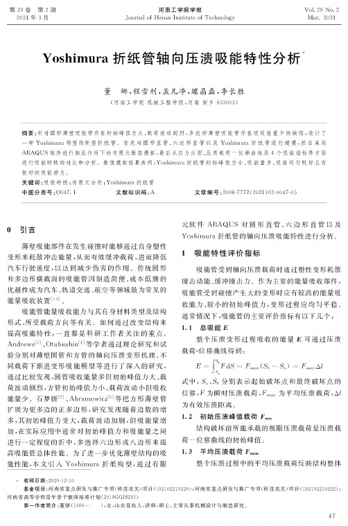
为了研究吸能管结构形状对吸能效果的影响 ,
本文采用传统的圆形直管、六边形直管与Yoshimura 折纸管作为研究对象。 如图)所示, 三种形状吸
能管的外接圆半径R = 50mm,总高度Hh = 240mm,壁厚t = 2mm。材料选用弹塑性材料,弹性 模量为205GPa,泊松比为0. 3,屈服强度为 235MPa,极限强度为375MPa。本文采用S3R壳单 元对吸能管进行网格划分,考虑到求解精度与效率, 网格尺寸约为6mm。
(d)
(b)正视图
(c)俯视图
图1 Yoshimura折纸管
(d)平面镶嵌图
3有限元分析
有限元方法将结构离散为有限个单元,单元之间 通过节点连接。通过建立平衡方程,可以求解节点的 位移和应力等物理量。通用有限元软件ABAQUS在 解决大变形、强非线性问题方面有较强的稳定性和较 高的精度,因此本文选用ABAQUS进行数值分析闪。 3. 1有限元模型的建立