DA092005 QPPB ISSUE 1.00
Laserbox 激光雕刻机 用户手册说明书

User ManualD1.1.2_KD010218000D1.3.5_KD010098000StatementWelcome to use Makeblock products!Before installing and using the product for the first time, please carefully read all the accompanying materials of the product to improve your experience with it. If you fail to use the product according to the instructions and requirements of the Manual, or mis-operate the product due to misunderstanding, etc., Makeblock Co., Ltd. (Shenzhen) will bear no responsibility for any loss resulting therefrom, except for losses due to improper installa-tion or operation by Makeblock professional maintenance personnel.Makeblock Co., Ltd. (Shenzhen) has collated the Manual rigorously and carefully, but we cannot guarantee that the Manual is completely free of error or omission.Makeblock Co., Ltd. (Shenzhen) is committed to continuously improving product functionality and service quality, and therefore reserves the right to change any product or so ware program described in the Manual and the contents of the Manual at any time without prior notice.The Manual is intended to help you use the product correctly and does not include any description of the product hardware and so ware configuration. For product configuration, please refer to the relevant contract (if any) and packing list, or consult your distributor. Pictures in the Manual are for reference only and the actual product may vary.Protected by copyright laws and regulations, the Manual shall not be reproduced or transcribed in any way, or be transmitted on any wired or wireless network in any manner, or be translated into any language without the prior written authorization of Makeblock Co., Ltd. (Shenzhen).ContentsSafety First (Important) 01List of Items 05Meet Your Laserbox 06Quick Operation GuideConnect the smart smoke purifier Start the LaserboxConnect a computer to the Laserbox Start cutting / engraving10Appendix 1: Cutting/Engraving Material Requirements29Appendix 2: Annular Indicator Status Description 3032Product Warranty InformationPause the task Cancel the task Clean chippingsBring sketch to life Image extractionMore Operations23More Features26Note: The above information may be subject to change due to objective factors, and please refer to the latest release of Makeblock. If you use the internet or phone call to get our support, additional fees may apply.Makeblock service informationPlease contact us if you find the actual product is inconsistent with the Manual during operation, or if you want to get the latest informa-tion, or have any questions or suggestions.Technicalsupport:*********************Safety First (Important)1. General safetyRead and get familiar with all safety protocols and procedures before operating the Laserbox. Users shall strictly follow all safety precautions and ensure that the Laserbox is properly assembled and in working order.01Please observe the following operating principles:Be sure to check the Laserbox for damage every time before use. Do not operate any damaged ordefective Laserbox in any way.Please keep the workspace clean and flat. Note that the laser tube is made of glass and is very fragile. If itis broken, the Laserbox will fail to work.Without authorization, please do not disassemble or change the Laserbox structure in any other way; andplease do not modify or decompile the operating system of the Laserbox.Please keep the inside of the Laserbox clean. Residues and chippings accumulated during cutting andengraving are dangerous and may cause fire. Clean the chippings and residues in the honeycomb paneland tray regularly.The working temperature of laser is between 5 °C and 25 °C. It is strictly prohibited to operate below 0 °C.2. Laser safetyUnder normal circumstances, the CO2 laser tube is completely enclosed in a casing during operation. The Laserbox has a safety interlock switch. If thelid is li ed during operation, the Laserbox will stop working to prevent harming people. No special precautions are required to ensure laser safety.The reference standard for laser safety is American National Standard for Safe Use of Lasers (Z136.1-2000), which is provided by the American NationalStandards Institute (ANSI). This reference is the basis for federal regulations and laser system manufacturers, as well as the laser safety guidelines ofOccupational Safety and Health Administration (OSHA). It contains details on the proper installation and use of laser systems.Please observe the following safety guidelines:Never operate the Laserbox with any parts removed, such as tray. Please note that the absence of any part of the Laserbox may expose the lasersystem and increase the risk of equipment damage. Remember that the CO2 laser beam is invisible.Do not engrave or cut any material that contains PVC or vinyl (processed plastics are not recommended). These materials (and other materialscontaining chlorine/chloride) can generate corrosive vapor that is extremely harmful to the human body and can cause damage to the Laserbox.Any damage caused by engraving or cutting any material containing PVC or vinyl is not covered by Makeblock’s warranty.Do not engrave or cut any unknown material. Vaporization/melting of many materials, include, but not limited to, PVC and polycarbonate, will releaseharmful smoke.Laser operation is prohibited when the lid/tray is li ed. Make sure that the Laserbox is closed by the lid/tray during operation and do not tamper withthe safety mechanism of the lid.Do not operate the Laserbox before properly connecting smoke purifier. Most materials produce irritating smoke when being processed.These include, but are not limited to, paints, varnishes, composite boards, and plastics that can produce hazardous compounds during processing.023.Fire safetyA high-density laser beam is used by the Laserbox to irradiate the material to be cut or engraved, so as to heat up the material surface and vaporize the material without burning. But most materials are inherently flammable and may be ignited to form an open flame that can burn down the Laserbox (even if it is made of flame-retardantmaterials) and its surroundings. Experience shows that vector cutting with a laser is most likely to produce an open flame. In particular, acrylic has proven to be extremely flammable in vector cutting.Please read the following warnings and suggestions carefully:Please note that stacked materials (especially organic materials such as paper) may cause flame propagation or increase the risk of material ignition.Never leave the Laserbox unattended during operation. There is a risk of fire if the Laserbox is started due to incorrect settings and le unattended for long periods of time, or if the Laserbox is mechanically or electrically malfunctioning during operation.Clean the Laserbox regularly. Excessive accumulation of residues and chippings from cutting and engraving would increase the risk of fire. Honeycomb panel and tray should be removed and cleaned periodically to ensure that there is no residue or chipping in the Laserbox.Keep the area around the Laserbox clean and free of cluttered flammable materials, explosives or volatile solvents such as acetone, alcohol or gasoline.Provide fire extinguishers, and perform regular maintenance and inspection.03044.Electrical equipment safetyLaser tube of the Laserbox has a silicone rubber casing, which can e ectively shield the internal power cord. If you find the cover is loose and the power cord is exposed, stop operating and contact customer service personnel.Please carefully read and strictly observe the following warnings and suggestions:When the Laserbox is connected to the power supply, do not open any access panel on the Laserbox to avoid harm from accidental contact with the power supply.When the Laserbox is connected to the power supply, do not touch the electronic-related area with your hands or other tools.Power button of the Laserbox is at the rear of it. Pressing (-) to power it on and pressing “o” to power it o .LaserboxButtonAnnular Indicator Power Button Power Interface USB InterfaceEthernet Cable Interface Smoke OutletAviation Interface1234567806User ManualList of Items Laserbox × 1Smoke Exhaust Pipe × 2Pipe Clamp × 3Aviation Connector × 1User Manual × 1Power Cord × 1USB Cable × 1Smart Smoke Purifier × 105Meet Your Laserbox12345678910111213Smart Smoke PurifierHEPA Composite Filter Indicator Aviation Interface Smoke Inlet Smoke Outlet12345Camera Laser Head TrayHoneycomb Panel Laser Tube910111213070812345Quick Operation GuideConnect the smart smoke purifierUse pipe clamps to hold the exhaust pipes:091012341.Connect the purifier with the 2m-exhaust pipe and lay the pipe to the window.Tips: You can also visit the website below to get the video tutorials.2.Connect the Laserbox and purifier with the 1.5m-exhaust pipe.3.Connect the Laserbox and purifier with the aviation connector.4.Connect the power supply.https:///maker-tools/laserbox-videoEthernet Wi-FiUSB Connect a computer to the LaserboxLaserbox so ware is required for the connection of a computer to the Laserbox. Please download and install the so ware at the following website.There are three ways to connect a computer to the Laserbox. Choose the best according to your situation.https:///maker-tools/laserbox11 Start the LaserboxA er pressing the power button, the laser head will automatically reset and calibrate. A er the first startup, the annular indicator will turn solid white. The startup process takes a while, and please be patient.121. Connect a computer to the Laserbox with the USB cable.2. Open the so ware, select “Connect to a new Laserbox” and click “Next”.3. Select “USB” and click “Next” to start the connection.4. Successful connection.Connect with the USB cable14131234Back Next Select your preferred connection mode.Device connectionUSB Wi -FiEthernet Cancel Next Select your preferred connection method.Device connectionConnect to a new Laserbox.Connect to a networked Laserbox.FinishConnected successfully!Go and enjoy the fun of creation!FinishConnected successfully!Go and enjoy the fun of creation!Back NextSelect your preferred connection mode.Device connectionUSB Wi -FiEthernet Cancel Next Select your preferred connection method.Device connectionConnect to a new LaserBox.Connect to a networked LaserBox.1. Connect your computer to the Laserbox with an Ethernet cable.2. Open the so ware, select “Connect to a new Laserbox” and click “Next”.3. Select “Ethernet” and click “Next” to start the connection.4. Successful connection.Connect with an Ethernet cable (not included in the package)11516243Cancel Next Select your preferred connection method.Device connectionConnect to a new LaserBox.Connect to a networked LaserBox.Back NextConnect to the LaserBox via Wi-FiWi-Fi NamePasswordBack NextSelect your preferred connection mode.Device connectionWi -FiEthernetUSB1. Connect a computer to the Laserbox with the USB cable.2. Open the so ware, select “Connect to a new Laserbox” and click “Next”.3. Select “Wi-Fi” and click “Next”.4. Connect to the existing Wi-Fi network.5. A er successful connection, you can disconnect the USB cable and wirelessly control the Laserbox.Wi-Fi wireless connection18171234Place the o icial materials in the Laserbox working area.Note: Cutting/Engraving Material Requirements can be found in the appendix.Start cutting / engraving20119Open the Laserbox so ware and select the sample image. You can also import or draw images yourself.Press the button on the Laserbox to start cutting/engraving.The task is completed when the annular indicator turns solid green.21222Click the “Start” button. TheLaserbox can automatically identify o icial materials and set cutting/en-graving parameters.3Click "Send" to send the image to the Laserbox. A er the transmis-sion is completed, the Laserbox would be ready, and the annular indicator would turn flashing blue.45速度功率雕刻126.3178.4Press and hold the button for 5 seconds.More OperationsPause the taskMethod 1: Click “Pause” in theso ware interface to pause the task.Method 2: Press the button on the Laserbox to pause the task. Press again to continue with the task.Method 3: Open the lid to pause the task. Close the lid and press the button on the Laserbox to continue with the task.Cancel the task1. Open the lid.Note: A er starting cutting/engraving, you can also cancel the task by clicking “Pause -> Cancel” in the Laserbox so ware interface.2324122. Press and hold the button for 5 seconds. A er the task is cancelled successfully, you will hear a beepsound and the annular indicator turns from red to blue.Method 1:Method 2:Method 3:密度MMore FeaturesNote: For optimal cutting / engraving e ect, it is recommended to use the Deli S550oil-based marker, draw the image as far as possible from the ring code and the edge of the material, and place the material in the center of the honeycomb panel. Only with copy paper and o icial materials, you can bring sketch to life. Damages caused by the use of other materials are not covered by Makeblock’s warranty service.Bring sketch to lifeClean chippings2526123Residues and chippingsaccumulated during operation of the Laserbox should be cleaned regularly, otherwise it may cause a fire. Pull out the tray as shown to clean up residues and chippings.Draw on copy paper or o icialmaterials with a black/red oil-based pen. For images drawn with a black oil-based pen, the Laserbox will cut along the contour and the black area will be engraved. Images drawn with a red oil-based pen will be cut directly along the handwriting.1. Draw an image, preferably with a Deli S550 oil-based marker.2. Place the material and close the lid.3. Press the button on the Laserbox to start the task.1. Place the object for image extraction.3. Successful image extraction.2. Start the Laserbox and select “Marquee” to put the image you want to extract in a selection box.The Laserbox has a built-in camera that extracts the surface image for further creation.Image extraction2728123Maximum dimensions for cutting: 500 (length) * 300 (width) * 22 (thickness) mm Materials for cutting/engraving:Materials not recommended:Note: The use of poor quality materials may result in poor cutting/engraving. It is recommended to use Makeblock o icial materials.The use of the materials not recommended above may damage the device, and the resulting damages are not covered by Makeblock’s warranty service.2930Appendix 1: Cutting/Engraving Material RequirementsAppendix 2: Annular Indicator Status DescriptionCardboard Paper Uneven materialHumid materialDirty materialOut-of-gauge materialWood boardAcrylic Leather Cloth Base plate ABS-based color boardPET RubberPlasticCorianWood veneerGlass fiberIndicator status DescriptionFlashing whiteThe system gets started.Waiting to connect.Completion.Abnormal.Sleep mode. It goes into the sleep mode from the standby mode a er 10 minutes idle.Solid whiteSolid blueIt is ready and the image has been sent successfully.Flashing blueSix indicators light up gradually Green breathing indicatorSolid redThe Laserbox firmware is being upgraded.Solid purpleSolid greenIt is in the standby mode and the Laserbox has been connected to the computer.It is in the working status, and the number ofindicators that are ON indicates the current progress.Declaration of conformity Hereby, Makeblock Co., Ltd., declares that this product is in compliance with the essential requirements and other relevant provisions of Directive RED 2014/53/EU and the RoHS directive 2011/65/EU3132Notes and instructions:①The above “warranty period” is from the date of purchase on the receipt, with the invoice date as a reference. Please keep your purchase invoice on record. In the absence of a valid invoice, the warranty period will be counted from the ex-factory date.② Laser tube warranty terms:<1> Makeblock promises to provide warranty service if the laser tube has a crack upon arrival.<2> Within the warranty period, Makeblock promises to provide warranty service if the laser tube has no visible damage on its appearance but it is malfunctioning (for instance, no laser light coming out) during LaserBox operation.<3> Within the warranty period, Makeblock will not provide warranty service, if the laser tube has a crack on its appearance during LaserBox operation, including but not limited to a crack caused by improper carrying or low operating environment temperature.Product Warranty InformationDECLARATION OF CONFORMITYCategoryMain Parts Consumable materials & AccessoriesPCB, motor, camera, laser tube, guide rail and conveyor belt, etc Filter cartridge and wood board, power cord, aviation connector, user manual, package and honeycomb panel etc.Parts NameTwelve(12) monthsNo applicable to this Limited Warranty. Makeblock only provides free replacement for the defective part upon receiving.Warranty Period3334Special NotesProduct informationProduct serial number:This warranty does not apply to Product and parts whose warranty period expires;Normal discoloration, wear, tear and consumption;Malfunction or damage caused by incorrect or improper use, maintenance or storage, such as: improper handling; use for purposes not as properly intended; improper insertion and removal of external equipment; drop or improper external force extrusion; contact or exposure to inappropriate temperature, solvent, acid, alkali, water immersion and other environments; and breaking & cracking, rusting and damage of products or parts (such as casing, components, circuits, etc.) due to insects, rat bites, or any foreign materials;Damage due to installation, repair, alteration or modification by anyone other than an authorized service center or personnel of Makeblock;Product or parts whose original identifying information has been modified, defaced or removed; Absence of a valid receipt or any other documents that can prove the warranty status;Malfunction or damage resulting from uses of so ware that are illegally licensed, non-standard or not available to the public;Malfunction or damage caused by virus infection, hacker attack or other malicious infringements;Malfunction or damage due to force majeure or accidents;Damage occurred on the product's way back to Makeblock for repair;Including but not limited to other non-design, technical, manufacture, quality issue;Products can run without interruption or error.If you run into issues above, please contact relevant parties for solutions, for which Makeblock is not held reliable.Remarks: Makeblock reserves the right, at its sole discretion, to interpret and amend this warranty policy at any time.The packing of the product, free gi s, consumable parts, and accessories do not apply to this Warranty. If you find any damage upon receiving, Makeblock will provide you free replacement. Please check timely the product a er the receipt thereof. Makeblock will charge certain fees if you would add packaging, accessories or require refurbishment service.None of any warranty service made by an authorized distributor is covered by this warranty policy, and Makeblock shall not be held liable. In order to receive any benefits from the distributor’s warranty and/or other policies, please keep any documents obtained during the purchase.In terms of discontinued products or the products which are going to be discontinued, Makeblock will publish relevant announcement and inform authorized distributors to notify customers of the deadline of the Warranty Period. Makeblock and its authorized distributors will terminate the warranty service a er the deadline of the Warranty Period.The Limited Warranty does not apply to products that were resold by unauthorized resellers.To the extent other warranty agreements are made during the purchase, those contracts confirmed by Makeblock shall prevail.。
博世 D7212 使用说明书
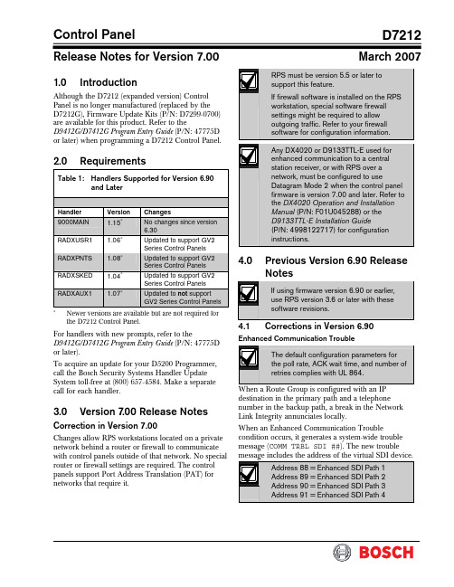
Control PanelD7212Release Notes for Version 7.00March 20071.0 IntroductionAlthough the D7212 (expanded version) Control Panel is no longer manufactured (replaced by the D7212G), Firmware Update Kits (P/N: D7299-0700) are available for this product. Refer to theD9412G/D7412G Program Entry Guide (P/N: 47775D or later) when programming a D7212 Control Panel.2.0 RequirementsTable 1: Handlers Supported for Version 6.90and LaterHandler Version Changes 9000MAIN 1.15∗No changes since version 6.30RADXUSR1 1.06∗Updated to support GV2 Series Control PanelsRADXPNTS 1.08∗Updated to support GV2 Series Control PanelsRADXSKED 1.04∗Updated to support GV2 Series Control PanelsRADXAUX1 1.07∗Updated to not support GV2 Series Control Panels∗Newer versions are available but are not required for the D7212 Control Panel.For handlers with new prompts, refer to theD9412G/D7412G Program Entry Guide (P/N: 47775D or later).To acquire an update for your D5200 Programmer, call the Bosch Security Systems Handler Update System toll-free at (800) 657-4584. Make a separate call for each handler.3.0 Version 7.00 Release NotesCorrection in Version 7.00Changes allow RPS workstations located on a private network behind a router or firewall to communicate with control panels outside of that network. No special router or firewall settings are required. The control panels support Port Address Translation (PAT) for networks that require it.4.0 Previous Version 6.90 ReleaseNotes4.1 Corrections in Version 6.90Enhanced Communication TroubleWhen a Route Group is configured with an IP destination in the primary path and a telephone number in the backup path, a break in the Network Link Integrity annunciates locally.When an Enhanced Communication Troublecondition occurs, it generates a system-wide trouble message (COMM TRBL SDI ##). The new troubleD7212The trouble condition is also sent through a backup path to the central station as Communication Trouble SDI ##, using the same virtual address numbers as the trouble messages. The communication trouble event also creates new Modem IIIa 2 messages that thecentral station might need to add to their automation software. Refer to Events 157 to 160 in the D6600 Computer Interface Manual (P/N: 4998122703) for the details of central station data changes. Unsupported Point TypePreviously, if the value of 11 was used with RADXPNTS version 1.06 or later when configuring the Point Index parameters, the control panel might not operate as expected. This condition is corrected so that the control panel responds to a P# Type value of 11 as a disabled point.5.0 Previous Version6.80 ReleaseNotes5.1Corrections in Version 6.805.1.1Local Event ReportingSeveral changes in this release prevent the controlpanel from sending local alarm events intermittently to the central stations. All local alarm events now remain local. 5.1.2Ethernet Link IntegrityFor UL 1610 Line Security (formerly Grade AA) Intrusion System installations and for UL 864 Commercial Fire installations, use the parametersshown in Table 2 when configuring the Heartbeat Poll. For additional details, refer to Programming PathNumbers and IP Addresses for Enhanced Communications in the D9412G/D7412G Program Entry GuideTable 2: Parameters for Heartbeat PollConfiguration in Version 6.801Number of IP Paths Poll Rate (sec) ACK Wait Time (sec)Number of Retries1 30 62 to 19 1 30 8 2 to 12 1 30 10 2 to 8 1 30 12 2 to 5 1 30 14 2 to3 1 60 6 2 to 14 1 60 8 2 to 8 1 60 10 2 to5 1 60 12 2 1 752 102 32 1 906 2 to 9 1 90 8 2 to 4 1 90 10 2 1 120 6 2 to 4 1 145 522 752 82 323 752 62 324 75252321 The parameters in this table are for Version 6.80 only . 2Recommended settings for the corresponding number of IP paths.5.2 Enhancements in Version6.80Summary Fire Relay SustainWhen the Silent Alarm Relay for Area 2 isprogrammed with 24, the Summary Fire Alarm Relay remains active until all Fire Alarms are cleared from the keypad display. The default operation is consistent with the Summary Fire Relay operation in Version 6.60 and older. This feature provides a method of maintaining fire strobes after the alarm bells are silenced.5.3 Known Issue in Version6.80When a Route Group is configured with an IP destination in the primary path and a telephone number in the backup path, a break in the Network Link Integrity does not annunciate locally.D72126.0 Previous Version 6.70 ReleaseNotesEnhancement in Version 6.70Arming Scope RestrictionsWhen the Silent Alarm Relay for Area 3 isprogrammed with 59, some prompts in the FunctionTable 3: Arming Scope RestrictionsMenu Function Function NumberDisabled Prompt Disarm Menu 1 DISARM ALL?Master Arm Delay 2 MASTER ARM ALL? Master Arm Instant3ARM INSTANT ALL?7.0Previous Version 6.60 Release Notes7.1Corrections in Version 6.60The changes made to the version 6.60 firmware affect only control panels with the ground fault detection circuit: the G-model control panels. Because the D7212 Control Panel does not have the ground fault detection circuit, this firmware upgrade does not change the control panel’s function.7.2Known Issues in Version 6.60•When a faulted local point is force armed, the central station should receive a Forced Close report for that point. The control panel does not send Forced Close reports for faulted local points. •If a local and a non-local point are faulted and force armed, the control panel does not send Forced Armed, Forced Point, or Forced Close Reports for the non-local point. A point is a local point if configured as follows: • Local While Armed : Yes •Local While Disarmed : Yes8.0 Previous Version 6.50 ReleaseNotesCorrections in Version 6.50Intermittent RF Low Battery eventsIn versions 6.30 and 6.40, Points 1 through 8 generate intermittent RF Low Battery events when devices connected to the on-board points change very quickly from normal to off-normal conditions. Firmware version 6.50 corrects this issue.When an RF Low Battery condition occurs on atransmitter, RF Low Battery appears on the D1255 or D1260 Keypad’s display. To determine whichtransmitter has the low battery condition, select one of the following: •View Log? function from the Service Menu (99 + ENT) on the keyboard, or•Diagnostics function, using the D8125INV. Refer to the D8125INV Operation and Installation Guide (P/N: 49690) for details.If the event is transmitted to the central station, the point number is included in the transmission.D72129.0 Previous Version 6.40 ReleaseNotes9.1Enhancements in Version 6.40Enabling the D1260 in a D7212 Control Panel 1. To enable D1260 Keypads, set the commandcenter menu item to Yes for the command center addresses where the D1260s reside.• In the Command Center Assignments section, the prompt is CC#EnhanceCmdCtr . •In the COMMAND CENTER (9000MAIN) section in RPS, the prompt is EnhancedCommand Center .Figure 1: Enhanced Command Center Prompt inRPS2. When power is applied, each D1260 checks thefirmware revision number that resides in the control panel. For each D1260 to work, theDisplay Revision (Command 59) must be enabled and not passcode protected. Refer to Figure 2 on page 4.•In the D5200, this function is located at: 9000MAIN USER INTERFACE Cmd Center FunctionsDisplay Rev •In RPS (Figure 2), this function is located at: USER INTERFACE Command Center FunctionsFigure 2: Enable Display Revision Prompt in RPS3. Before exiting RPS, reset the control panel aftercompleting an RPS programming session:A.Click the Reset Panel checkbox B. Click OK .Refer to Figure 3.Figure 3: End Session Dialog BoxFigure 4: Keypad DisplayD72129.2Corrections in Version 6.40Duplicate Events Do Not Report under Comm Fail ConditionsVersion 6.40 corrects the following problem:When a Comm Fail condition occurs in Route Group 1, Route Group 2, or both, D7212 does not send duplicate events to Route Groups 3 and 4 whenduplicate events are programmed for Route Groups 2, 3, 4, or all groups.Support for D1260 Not in Version 6.30 as Stated in LiteratureThe D9412G/D7412G Program Entry Guide(P/N: 47775D) and the D7212 Release Notes for v6.30 (P/N: 34699N) state incorrectly that Alpha V Command Center (keypad) support is available in version 6.30.Only version 6.40 or higher can support the D1260 Alpha V Command Center (keypad) Watchdog Reset EventsVersion 6.40 corrects Watchdog Reset eventsgenerated when a SKED is used to arm a disabled area or a Closing Window and Auto Close prompt is set to Yes (in Area Wide Open/Close ). BFSK FormatBefore version 6.40, the control panel did not send Burglary Restoral reports when using the BFSK communication format. Version 6.40 corrects this issue.Fail to Execute EventsBefore version 6.40, Fail To Execute events incorrectly identified the serial device interface (SDI) device associated with the event. Version 6.40 corrects this issue.Programming Point Indexes for Points 240 – 247 In version 6.30 for the D7412G and D7212 Control Panels, if you use a D5200 to assign point Points 240 through 247, the control panel ignores these points and mistakenly shows missing conditions. Version 6.40 corrects this issue.9.3Known Issues in Version 6.40Disconnecting Battery during Walk Test Causes D1260 to Stop RespondingWhen the control panel’s battery is disconnected and then reconnected during a Walk Test, the D1260 stops responding and displays Retrieving panel info . The control panel must be restarted to clear the keypad.Areas Armed to “All on instant” Do Not Show Area Text in D1260 View Area StatusWhen arming areas to All on Instant, area text does not appear when using the View Area Status menu function on the D1260. BFSK FormatSupervisory and Fire Supervisory events cannot be29.4 Programming TipsNetCom CommunicationsIn applications where both the primary and backup paths are programmed to send an IP address, the Path # Poll Rate value for the backup IP address should be set to 0. In the D9412G/D7412G Program Entry Guide (P/N: 47775), refer to: •Routing and Enhanced Routing for information about primary and backup paths.•Enhanced Communications in the RADXAUX1Handler section for information about Path # Poll Rate .D7212NotesD7212 NotesD7212© 2007 Bosch Security Systems, Inc.130 Perinton Parkway, Fairport, NY 14450-9199 USACustomer Service: (800) 289-0096; Technical Support: (888) 886-6189 F01U034872-02Release Notes for Version 7.003/07D7212Page 8 of 8。
OKI5300印表机的错误代码

如果错误代码您要找的是不是在下面的表格,然后发送电子邮件至support@,我们会找出它的意思。
错误代码描述复苏001机器检查例外一个严重的问题,已发现的铜委员会寻求注意服务的人如果重新启动打印机不正确的问题002DSI公司例外当程式,企图寻找了一个无效的地址注意:24位数字的地址(通常是3 ),然后重新启动打印机。
检查重复性如果可能的。
重复同样的行动,重新启动后打印机和检查,如果同样的服务呼叫讯息出现003ISI的例外当程式,企图寻找了一个无效的地址注意:24位数字的地址(通常是3 ),然后重新启动打印机。
检查重复性如果可能的。
重复同样的行动,重新启动后打印机和检查,如果同样的服务呼叫讯息出现004对齐例外当程式,企图寻找了一个无效的地址注意:24位数字的地址(通常是3 ),然后重新启动打印机。
检查重复性如果可能的。
重复同样的行动,重新启动后打印机和检查,如果同样的服务呼叫讯息出现005程序例外该程序已尝试探讨了一个无效的地址注意:24位数字的地址(通常是3 ),然后重新启动打印机。
检查重复性如果可能的。
重复同样的行动,重新启动后打印机和检查,如果同样的服务呼叫讯息出现006浮动点无法例外该程序已尝试探讨了一个无效的地址注意:24位数字的地址(通常是3 )款中,然后重新启动打印机。
检查重复性如果可能的。
重复同样的行动,重新启动后打印机和检查,如果同样的服务呼叫讯息出现007 教学地址断点例外注意:24位数字的地址(通常是3 ),该程序已尝试探讨了一个无效的地址然后重新启动打印机。
检查重复性如果可能的。
重复同样的行动,重新启动后打印机和检查,如果同样的服务呼叫讯息出现030铜slot1的DIMM内存检查错误一个错误侦测到已在运作的检查,羊年在插槽1 (或驻地RAM的模式,有一个居民的RAM )。
注意:24位数字的地址(通常是3 ),然后重新启动打印机。
检查重复性如果可能的。
重复同样的行动,重新启动后打印机和检查,如果同样的服务呼叫讯息出现030铜slot1的DIMM内存检查错误一个错误侦测到已在运作的检查,羊年在插槽1 (或驻地RAM的模式,有一个居民的RAM )。
富士通 生活本U9312数据表说明书
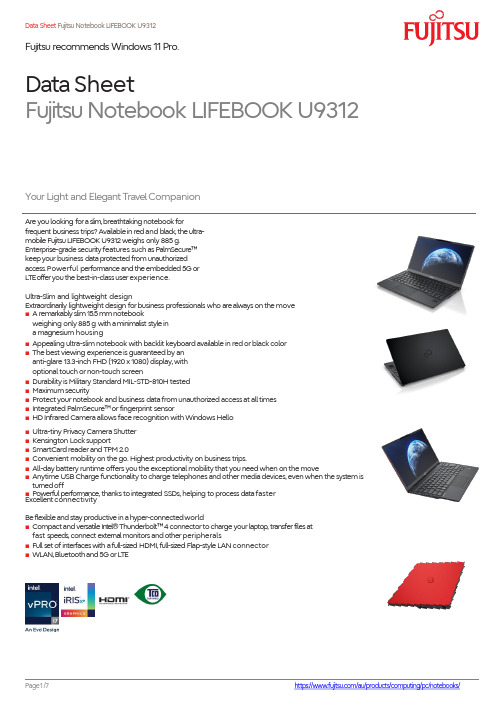
Data Sheet Fujitsu Notebook LIFEBOOK U9312Fujitsu recommends Windows 11Pro.Data SheetFujitsu Notebook LIFEBOOK U9312Are you looking foraslim,breathtakingnotebookforfrequent business trips?Availablein redand black,the ultra-mobile Fujitsu LIFEBOOK U9312weighs only 885g.Enterprise-grade securityfeatures such asPalmSecure ™keepyour business dataprotected fromunauthorized access.Powerful performance andthe embedded 5Gor L T Eofferyou thebest-in-classuserexperience.Ultra-Slim and lightweight designExtraordinarily lightweight design forbusiness professionals who arealways on the move ■A remarkablyslim15.5mmnotebookweighing only 885 g with aminimalist style in a magnesium housing■Appealing ultra-slim notebook with backlit keyboard available in red or black color ■The best viewing experience is guaranteed by an anti-glare 13.3-inch FHD (1920 x 1080) display, with optional touch or non-touch screen■Durability is Military Standard MIL-STD-810H tested ■Maximum security■Protect your notebook and business data from unauthorized access at all times ■Integrated PalmSecure ™or fingerprint sensor■HD Infrared Camera allows face recognition with Windows Hello■Ultra-tiny Privacy Camera Shutter ■Kensington Lock support■SmartCard reader and TPM 2.0■Convenient mobility on the go. Highest productivity on business trips.■All-day battery runtime offers you the exceptional mobility that you need when on the move■Anytime USB Charge functionality to charge telephones and other media devices, even when the system is turnedoff■Powerful performance,thanks to integrated SSDs,helping to process data faster Your Light and ElegantTravelCompanionExcellent connectivityBeflexibleandstay productive in ahyper-connectedworld■Compactand versatileI n t e l ®Thunderbolt ™4connectorto charge your laptop,transferfilesat fast speeds,connect externalmonitors andotherperipherals■Full set of interfaceswith afull-sized HDMI,full-sized Flap-style LAN connector ■WLAN,Bluetoothand5Gor L TEComponentsBaseunit LIFEBOOK U9312black LIFEBOOK U9312redOperating systemsOperating system pre-installed Windows11 P r o.FujitsurecommendsWindows11Proforbusiness. Windows 11 HomeWindows10 P r o.FujitsurecommendsWindows11Proforbusiness.Microsoft OS support information Aftertheendoftheproduct lifeFujitsuwill continue totestand support allupcoming Windows releases foraperiod ofmaximum5years,depending on theavailable extensionof hardwareservicesthrough FujitsuWarranty topups.Fordetailspleasesee“Fujitsu Service StatementforWindows General Availability Channel”athttps:///IndexProdSupport.asp?lng=com&OpenTab=Operating system notes TheuseofWindows Operating Systemissubjectto acceptanceof theEndUserLicense Agreement ofMicrosoft as applicable under the relevant Microsoft program.Processor I n t e l®Core™i7-1265Uprocessor(10Cores,up to4.8GHz)I n t e l®Core™i5-1245Uprocessor(10Cores,upto4.4GHz)I n t e l®Core™i5-1235Uprocessor (10Cores,up to4.4GHz)**Processor only forr etai l,SMB,educationandgovernmentHarddiskdrives(internal)PCIe-SSD,512 GBM.2NVMe module,SEDPCIe-SSD,256 GBM.2NVMe module,SEDPCIe-SSD,2T BM.2NVMemodule,SEDPCIe-SSD,1T BM.2NVMe module,SEDHard disknotes Accessiblecapacity mayv ar y,also depending on usedsoftware.One Gigabyte equals one billion bytes,when referringtoharddiskdrivecapacity.Upto 20GBof HDDspace isreserved forsystemrecoveryDurability in accordancewith the manufacturer’s indications on readandwrite cycles. Interfaceaddoncards/components(optional)4G/5G(optional)FibocomFM350-GL(5GSub-6/Cat.19)(Downlink speed 5G-3740 MB/s,4G-1600 MB/s,Uplink speed5G-835 MB/s, 4G -211MB/s)Display33.8cm(13.3-inch),LEDbacklight,FHD,1,920x1,080pixel,Anti-glare IPS display,400c d/m²,1000:133.8cm(13.3-inch),IPS,FHD,1,920x1,080pixel,Anti-glare multi-touch,350c d/m²,1500:1MultimediaCamera Optional:Built-in HD webcamBase unitBaseunit LIFEBOOK U9312black LIFEBOOK U9312redGeneral system informationChipset Integrated in CPUGeneral system informationSupportedcapacity RAM(min.)8GBSupportedcapacity RAM(max.)32GBMemorynotes8GB/16GB/32GB onboardLPDDR4x (4,266MHz)DualchannelsupportLAN10/100/1,000MBit/s I n t e l®I219LMIntegrated WLAN IntelWi-F i6EAX211-WLAN,B T,SRD cat.2BIOS version UEFI Specification2.8BIOS features InsydeH2OBIOSAudio type OnboardAudio codec RealtekALC257Audio features2xbuilt-in speakers(stereo)MIL-STD tested Y e s,selectedMIL-STD-810H tests passed.MIL-STD-810H testresults arenot aguaranteeof futureperformance under identified testconditions. Accidental damage is not coveredunder standardinternational limited warranty.Color Black RedMaterial Magnesium MagnesiumDisplayDiagonal Size33.8cm(13.3-inch)Resolution(native)1,920 x1,080pixelGraphicsBaseunit LIFEBOOKU9312black LIFEBOOK U9312redGraphicsbrand name I n t e l®I r i s®XeGraphics I n t e l®I r i s®XeGraphicsGraphicsnotes Sharedmemorydepending on mainmemorysize andoperating systemInterfacesAudio: line-out/headphone1(comboport with Audio line-in)1(comboport with Audio line-in)Internal microphones2xdigital arraymicrophones(optional)2xdigital arraymicrophones(optional)USB3.2Gen1(5Gbps)total2xType-A(1with Anytime USBchargefunctionality)2xType-A(1with Anytime USBchargefunctionality)USB4.0Gen3(20Gbps) total2xType-C I n t e l® Thunderbolt™4(40 Gbps),Power Delivery(15W),DPout 2xType-C I n t e l® Thunderbolt™4(40 Gbps), Power Delivery(15W),DPoutUSBType-C USB4Gen3Thunderbolt™4,Power Delivery(15W),DP1.4USB4Gen3Thunderbolt™4,Power Delivery(15W),DP 1.4HDMI1Supports4k@60Hzasspecifiedin HDMI2.01Supports4k@60Hzasspecifiedin HDMI2.0 Ethernet(RJ-45)11Memorycardslots1SD4.0 StandardSD/microSD cardSDHC/microSDHC cardSDXC/microSDXC cardSpeedClass:uptoUHS-II 1SD4.0 StandardSD/microSD card SDHC/microSDHC card SDXC/microSDXC card SpeedClass:uptoUHS-IISmartCard slot1(optional)1(optional)SIM cardslot1(Nano-SIM,only formodelswith integrated5G/4G module)1(Nano-SIM,only formodelswith integrated 5G/4G module)eSIM card eSIM supported-integrated in4G/5GL T EModule eSIM supported-integrated in4G/5GL T EModule Docking connectorforPortReplicatorUSBType-C Portreplicator USBType-C PortreplicatorKensington Locksupport11Port Replicatorinterfaces(optional)USBType-C PR Thunderbolt™4PRDC-in1(19V/90Wrequired)1(20V/170W required)Poweron switch11Audio:comments1Combojackforheadsetusage1CombojackforheadsetusageDisplayPort1xV1.22xV1.4++VGA1---HDMI text1V2.0bPort Replicatorinterfaces(optional)Interface Notes3xType-A-5V/0.9A,4.5W1xType-C-15W1xType-C-Upto 60W(PD v2.0-1.1)poweroutputtoclientor 4.5Winput 2xType-A-5V/0.9A,4.5W1xType-A-5V/2.4A,12W2xType-C-5V,1.5A/4.5W charging port1xType-C-T B T4upto 60W(PDv2.0-1.1),5-20V/3.0A upstream(P C),Intel AMTsupport(vPRO)1xType-C-T B T4upto 15W(PDv2.0-1.1),5V/3.0A downstream,power outputtoclientKensington Locksupport no1Ethernet(RJ-45)11(10/100/1000Mbit/s,2,5Gbps)Notes Number of simultaneous useddisplays andits possibleresolutions andfrequencies dependon mobile systemand display interface type.Pleaseconsult alwaysalso themanualofthe connectedclient.Keyboardandpointing devicesBacklitkeyboardw/otouchstickNumber ofkeyboardkeys:85,Keyboardpitch:19 m m,Keyboardstroke:1.5mmMulti gesture touchpad with twomouse buttonsWireless technologiesAntennas 2 Dual bandWLAN antennas,2+2L T EantennasoptionalBluetooth v5.2Integrated WLAN IntelWi-F i6EAX211-WLAN,B T,SRD cat.2WLANencryption WP A/WP A2/WP A3(Wi-F i ProtectedAccess)WLANnotes WiFi6Eis supportedbyWindows11OS only-Windows10 OS supportsWiFi6only.#Import and usageaccording to country-specific regulations.Integrated WWAN(5G)L T EFibocomFM350-GL(Sub-6/Cat.19)-UMTS,LTE,5GWWANnotes OptionalGPS Embeddedin4G/5Gmoduleif configured withWWANPowersupplyACAdapter20V/65W(3.25A),100V-240V,50Hz -60H z,3-pin(grounded)Type-C AC-Adapter slim&light 20V/65W(3.25A),100V-240V,50Hz -60H z,3-pin (grounded)Type-C AC-Adapter slim&lightNotes65WAC adapterforusage with system/min.90WAC Adapter forusage with PortReplicator 65WAC adapterforusage with system/min.90W AC Adapter forusage with PortReplicatorRatedvoltage range100V -240V (AC Input)100V -240V (AC Input)Rated frequency range50Hz-60Hz50Hz-60Hz1stbattery Lithiumpolymerbattery4-cell,64Wh,4,196mAh Lithiumpolymerbattery4-cell,64Wh,4,196mAh Battery features FastCharge:Upto 80%in1h FastCharge:Upto 80%in1hRuntime1st battery TBC TBCNoise emissionNoise emission Pleaser efertotheEcoDeclarationDimensions/Weight/EnvironmentalDimensions(W xD xH)307x197x15.5mm12.09x7.76x0.61inchWeight starting at885gWeight(lbs)starting at1.95lbsWeight notes Weight mayvarydepending on actualconfigurationOperating ambient temperature5-35°C(41-95°F)Operating relative humidity20-80%ComplianceProduct LIFEBOOK U9312Europe CECBGlobal TCOCertified9.0Additional SoftwareAdditional software(preinstalled)Fujitsu Plugfree Network(network managementutility)Fujitsu Anytime USB Charge UtilityFujitsu Battery UtilityFujitsu FunctionManagerFujitsu DeskUpdate(driver andutility tool)Additional software(optional)Microsoft Office(need to buy license to activate the pre-installed MicrosoftOffice) Drivers &Utilities DVD(DUDVD)RecoveryDVD forWindows®Additional software(notes)Useof additional softwareis subjectto proactive acceptanceofthe respective EndUserLicenseAgreementas applicable forthe relevant softwarewhether preinstalled oroptional.This also appliesforanyavailable patches thereof.ManageabilityManageability technology I n t e l®vPro™technology/iAMT(dependingonprocessor) PXEBoot codeWake-on-LANManageability software DeskViewClientDeskViewInstant BIOS ManagementSupportedstandards WMI(Windows ManagementInstrumentation)PXE(Preboot ExecutionEnvironment)DMI(DesktopManagementInterface)SMBIOS(SystemManagementBIOS) CIM(CommonInformation Model)BootP(made4you)Manageability link /fts/manageabilityPhysical Security Kensington LocksupportSystemandBIOS Security Userand supervisor BIOSpassword EraseDiskOptional:Trusted Platform Module(TPM2.0)UserSecurity Accessprotectionvia external SmartCardreader(optional)Hard diskpasswordAuthConductor Client Basic(secureauthentication solution)Embedded P al m S ecur e®sensor(optional) Embedded fingerprintsensor(optional)Accessprotectionvia internal SmartCard reader (optional) Hard diskpassword AuthConductor Client Basic(secure authentication solution)Embedded P alm S ecur e®sensor (optional)Embedded fingerprintsensor(optional)SecurityNotes Thesecurity features included in theproduct alonecannot protectfromanyand allintrusion attemptsandcyberattacks.Foran adequate overalllevelof ITsecurity,further ITsecurity measures(e.g.supplementaryvirusscannersettings,firewall,access rights management,encryption etc.)must be adoptedindependentlyof theavailable systemconfiguration options. HencetheoverallITsecurity fortheproductis within the soleresponsibility of therespective user/administrator ofthe product.WarrantyWarranty period 3 years Next Business DayWarranty type Onsite Service within metro areasWarrantyT er m s&Conditions https:///au/support/client-computing-devices/notebooks/Digitalbug fixes Subject to availability and following their generic release forthe product,bug fixes and function-preservingpatches forproduct-related software(firmware)canbe downloaded fromthe technical support a t:https:///freeof chargeby entering therespective product serial number.Forapplicationsoftwaresuppliedtogether with the product,pleasedirectlyr efertothe support websites of therespectivesoftwaremanufacturer.ProductSupport Services-theperfectextensionRecommendedService9x5,Onsite ResponseT i m e:Next BusinessDaySparePartsavailability5yearsafterendofproduct lifeService Weblink /emeia/products/product-support-services/Thunderbolt ™4Port ReplicatorFirstThunderbolt ™Port Replicatoron the marketproviding enhanced security and fullsupport ofI n t e l ®AMT(vPro®).Theuniversalport caneasily connectalmosteverything with asingle cable andhigh speed-datatransfer.This smart workspace solution keepsyour deskcleanandtidy.USBType-C Port Replicator2Connecttoyour peripherals.Adapt tothetaskon demand.The universal USBType-C interface supports you toget your peripheral devices connectedeasily.MultiplyyourUSB portsto connectyour peripheralsas wellasyour externaldisplay via HDMI,DisplayPort or VGA.Youalso canchargeyour external USBdeviceswithouttheneedof any additional charger.RecommendedAccessoriesMore informationFujitsu products,solutions&servicesIn addition toFujitsuTabletLIFEBOOKU9312,Fujitsuprovides arange ofplatform solutions.They combine reliableFujitsu productswith thebest inservices,know-how,andworldwidepartnerships.Fujitsu PortfolioBuilding on industrystandards,Fujitsu offers afullportfolio of IThardwareand software products,services,solutions, andcloud offerings,ranging from clients to data centersolutions,and includes thebroad stackof Business Solutions,aswellasthefullstack of Cloud offering.This allowscustomerst o leverage alternative sourcing and delivery models t o increase th ei r business agility an d t o improve th ei r I T operation’s reliability.Computing Products/global/products/ computing/Softwarehttps:///au/support/client-com puting-devices/notebooks/More informationTo learnmoreabout FujitsuTabletLIFEBOOK U9312pleasecontact yourFujitsu sales representative or FujitsuBusiness partner,or visit ourwebsite.https:///au/products/computing/pc/notebooks/Fujitsu Green Policy Innovation is ourworldwideproject forreducingburdenson theenvironment.Using our global know-h ow,weaimtocontribute tothecreationofasustainable environment forfuturegenerations through IT.Pleasefind further informationatSustainable Manufacturing -FujitsuUvance: Fujitsu AustraliaCopyrightsAllrights reserved,includingintellectual propertyrights.Changestotechnical data reserved.Deliveryissubjectto availability. Designationsmaybe trademarksand/or copyrightsof the respective manufacturer,theuseofwhich by thirdparties fortheir ownpurposesmayinfringe therights ofsuch owner.Copyright 2022 Fujitsu LimitedPleasenotethatthedatasheet reflectsthe technical specification with themaximum selectionof components forthenamed system andnot thedetailedscope of delivery.Thescope ofdelivery isdefined by theselectionofcomponentsatthe timeof ordering.Technical datais subject tomodificationand delivery subject to availability.Anyliability thatthedataand illustrationsarecomplete, actual,or correct isexcluded.Designations maybe trademarksand/orcopyrights of the respective owner,theuseofwhichby third parties fortheir ownpurposesmayinfringe therightsof suchowner.T h e overall product h as b een designedand manufactured f o r general offi ce u s e,regular personal use,andordinaryindustrial use.Fujitsu green policy innovationDisclaimerCONTACT FujitsuProduct Team Fujitsu Product Portfolio Website:Allrights reserved,includingintellectualpropertyrights.Changesto technicaldatareserved.Deliveryis subjectto availability.Designations maybetrademarksand/orcopyrights of therespectivemanufacturer,theuseofwhich by thirdpartiesfortheir own purposes mayinfringetherights ofsuch owner.Copyright2022FujitsuProduct。
LARA-Dio iOS安装手册说明书

Installation manual LARA-Dio Application for iOSContent1. Introduction (3)2. Install the app on your iOS mobile phone (3)3. Basic settings (4)4. Application Control (6)1. IntroductionLARA-Dio is complementary to the iNELS Multimedia Intelligent Wired System which allows you to control your LARA Radio audio sphere from a smart iOS-enabled phone.The main advantage of the application is the ability to control all audios from a single location.2. Install the app on your iOS mobile phoneDownload the LARA-Dio app to your mobile phone from App Store.When you open App Store, enter iNels in the search engine. Select LARA-Dio from the list and run it.Press the Install button to confirm. Wait for the installation; this may take several seconds (depending on your phone type).3. Basic settings∙Launch the application by pressing the Lara icon .∙When you first start, the two options for adding the LARA Radio are displayed.o NEW SEARCH - After pressing the button, all LARA Radio(s) available on your network will automatically be searched for. A list appears from which you can add LARA Radioindividually.o ADD MANAGER - here you enter the required login details required by LARA Radio (device name, static IP address, login name, password). By default, the LARA Radiologin name set to admin and password elkoep.After the LARA Radio has been successfully added, the radio list is automatically downloadedand the application is set to the default screen from which you can control LARA Radio.Button Settings MUTE - mutes volumeto minimumVolume controlName of the radio station played Control buttons: previous / next radio;play / stop Mark your favoriteradio4. Application Control∙ Press the List button to enter the list of your added LARA Radio. By touching a title or a dot, you can control and edit the LARA Radio.∙The middle icon is used to update the radio list stored in the LARA Radio.∙ Press Radio list button to enter the list of all radio stations you have set.Press the Heart button to assign / remove the marked radio from your favourite list.Press the station name to control the radio.∙With the Playlist button, you will enter the list of songs stored in your phone.Touching the track will play it.Return to the Home screen - just press the play button.Playlist saved onyour phonePreview analbum coverWhen you press the Favourite radio station button, the list you have defined lets you controlthe radio.You can also add individual radio stations directly from the main screen to the favourites list by pressing the heart symbol (top right).Favourite radio stationsWhen the Setup button is pressed, the grey side panel is hidden, where you can press theSettings bar to get to the setup menu.Number of Added LARA Radio(s) Pencil icon - foreditingTrash icon - to removeNameManual additionAutomatic search。
OKI新错误代码查询
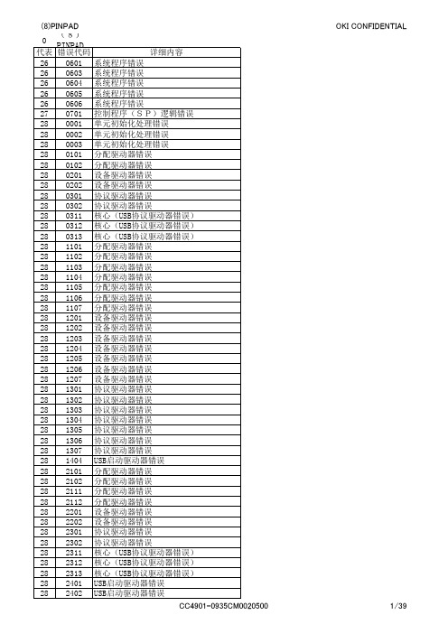
OKI CONFIDENTIAL
1/39
(8)PINPAD 0 (8)PINPAD Service Provider(密码键盘) 代表 错误代码 详细内容 28 2410 USB启动驱动器错误 28 2411 USB启动驱动器错误 28 2412 USB启动驱动器错误 28 3101 分配驱动器错误 28 3102 分配驱动器错误 28 3111 分配驱动器错误 28 3112 分配驱动器错误 28 3201 设备驱动器错误 28 3202 设备驱动器错误 28 3301 协议驱动器错误 28 3302 协议驱动器错误 28 3311 USB协议驱动器错误 28 3312 USB协议驱动器错误 28 3313 USB协议驱动器错误 28 3314 USB协议驱动器错误 28 3401 USB启动驱动器错误 28 3410 USB启动驱动器错误 28 3411 USB启动驱动器错误 28 4101 分配驱动器错误 28 4102 分配驱动器错误 28 4103 分配驱动器错误 28 4104 分配驱动器错误 28 4105 分配驱动器错误 28 4106 分配驱动器错误 28 4107 分配驱动器错误 28 4108 分配驱动器错误 28 4109 分配驱动器错误 28 4111 分配驱动器错误 28 4112 分配驱动器错误 28 4113 分配驱动器错误 28 4114 分配驱动器错误 28 4115 分配驱动器错误 28 4201 设备驱动器错误 28 4202 设备驱动器错误 28 4203 设备驱动器错误 28 4204 设备驱动器错误 28 4205 设备驱动器错误 28 4206 设备驱动器错误 28 4207 设备驱动器错误 28 4208 设备驱动器错误 28 4209 设备驱动器错误 28 4211 设备驱动器错误 28 4212 设备驱动器错误 28 4213 设备驱动器错误 28 4214 设备驱动器错误 28 4215 设备驱动器错误 28 4301 协议驱动器错误 28 4302 协议驱动器错误 28 4303 协议驱动器错误 28 4304 协议驱动器错误 28 4305 协议驱动器错误 28 4306 协议驱动器错误 28 4307 协议驱动器错误 CC4901-0935CM0020500
浦发拓温暖系统热泵分系列产品说明书

Product DataSplit System Heat Pump4TWR4018G1000A Array 4TWR4024G1000A4TWR4030G1000A4TWR4036G1000A4TWR4042G1000A4TWR4048G1000A4TWR4060G1000AN o t e:“Graphics in this document are for representationonly.Actual model may differ in appearance.”April202022-1765-13J-E NProduct Specifications(a)Certified in accordance with the Unitary Air-conditioner equipment certification program which is based on AHRI standard210/240.(b)Calculated in accordance with N.E.C.Only use HACR circuit breakers or fuses.(c)Reference the outdoor unit ship-with literature for refrigerant piping length and lift guidelines.Reference the refrigerant piping software pub#32-3312-xx or refrigerant piping application guide SS-APG006-xx for long line sets or specialty applications(xx denotes latest revision).(d)The outdoor condensing units are factory charged with the system charge required for the outdoor condensing unit,ten(10)feet of tested connecting line,and the smallest rated indoor evaporative coil match.Always verify proper system charge via subcooling(TXV/EEV)or superheat(fixed orifice)per the unit nameplate.(e)25,30,35and50foot linesets available.For a complete listing of lineset options available from equipment or supply stores,refer to the Trane Residentialand Light Commercial Product Handbook.P r o d u c t S p e c i f i c a t i o n s(a)Certified in accordance with the Unitary Air-conditioner equipment certification program which is based on AHRI standard210/240.(b)Calculated in accordance with N.E.C.Only use HACR circuit breakers or fuses.(c)Reference the outdoor unit ship-with literature for refrigerant piping length and lift guidelines.Reference the refrigerant piping software pub#32-3312-xx or refrigerant piping application guide SS-APG006-xx for long line sets or specialty applications(xx denotes latest revision).(d)The outdoor condensing units are factory charged with the system charge required for the outdoor condensing unit,ten(10)feet of tested connecting line,and the smallest rated indoor evaporative coil match.Always verify proper system charge via subcooling(TXV/EEV)or superheat(fixed orifice)per the unit nameplate.(e)25,30,35and50foot linesets available.For a complete listing of lineset options available from equipment or supply stores,refer to the Trane Residentialand Light Commercial Product Handbook.Accessory Description and UsageA n t i-S h o r t C y c l e T i m e r—Solid state timing device that prevents compressor recycling untilfive(5)minutes have elapsed after satisfying call or power e in area withquestionable power delivery,commercial applications,long lineset,etc.E v a p o r a t i o n D e f r o s t C o n t r o l—SPST Temperature actuated switch that cycles the condenseroff as indoor coil reaches freeze-up ed for low ambient cooling to30°F with TXV.R u b b e r I s o l a t o r s—Five(5)large rubber donuts to isolate condensing unit from transmittingenergy into mounting frame or e on any application where sound transmission needs tobe minimized.H a r d S t a r t K i t—Start capacitor and relay to assist compressor motor e in areas withmarginal power supply,on long linesets,low ambient conditions,etc.E x t r e m e C o n d i t i o n M o u n t K i t—Bracket kits to securely mount condensing unit to a frame orpad without removing any e in areas with high winds,or on commercial roof tops,etc.A H R I S t a n d a r d C a p a c i t y R a t i n g C o n d i t i o n sAHRI Standard210/240Rating Conditions1.Cooling80°F DB,67°F WB air entering indoor coil,95°F DB air entering outdoor coil.2.High Temperature Heating47°F DB,43°F WB air entering outdoor coil,70°F DB air enteringindoor coil.3.Low Temperature Heating17°F DB air entering indoor coil.4.Rated indoor airflow for heating is the same as for cooling.A H R I S t a n d a r d270R a t i n g C o n d i t i o n s—(Noise rating numbers are determiend with the unit incooling operations.)Standard Noise Rating number is at95°F outdoor air.Model NomenclatureOutdoor Units3 = 134 = 145 = 15Schematic DiagramsFigure 1. 1.5,2.0,2.5&3.5TonModelsFigure 2. 1.5,2.0,2.5&3.5TonModelsS c h e m a t i c D i a g r a m sFigure 3. 3.0TonS c h e m a t i c D i a g r a m sFigure 4.4and 5TonModelsS c h e m a t i c D i a g r a m sFigure 5.4and 5TonModelsS c h e m a t i c D i a g r a m sOutline DrawingMechanical Specification OptionsG e n e r a lThe outdoor condensing units are factory charged with the system charge required for theoutdoor condensing unit,ten(10)feet of tested connecting line,and the smallest rated indoorevaporative coil match.This unit is designed to operate at outdoor ambient temperatures as highas115°F.Cooling capacities are matched with a wide selection of air handlers and furnace coilsthat are AHRI certified.The unit is certified to UL1995.Exterior is designed for outdoorapplication.C a s i n gUnit casing is constructed of heavy gauge,galvanized steel and painted with a weather-resistantpowder paint finish.The corner panels are prepainted.All panels are subjected to our1,000hoursalt spray test.R e f r i g e r a n t C o n t r o l sRefrigeration system controls include condenser fan,compressor contactor and low and highpressure switches.A factory supplied,field installed liquid line drier is standard.C o m p r e s s o rThe compressor features internal over temperature and pressure protection.Other featuresinclude:Centrifugal oil pump and low vibration and noise.C o n d e n s e r C o i lThe outdoor coil provides low airflow resistance and efficient heat transfer.The coil is protectedon all four sides by louvered panels.L o w A m b i e n t C o o l i n gAs manufactured,this system has a cooling capacity to55°F.The addition of an evaporatordefrost control permits operation to40°F.The addition of an evaporator defrost control with TXVpermits low ambient cooling to30°F.The addition of the BAYLOAM107A low ambient kit permits ambient cooling to20°F.T h e r m o s t a t s—Cooling only and heat/cooling(manual and automatic change over).Sub-base tomatch thermostat and locking thermostat cover.22-1765-13J-EN11Trane-by Trane Technologies(NYSE:TT),a global innovator-creates comfortable,energy efficient indoor environments for commercial and residential applications.For more information,please visit or .The AHRI Certified mark indicates Trane U.S.Inc.participation in the AHRI Certification program.For verification of individual certified products,go to ahridirectory. org.Trane has a policy of continuous data improvement and it reserves the right to change design and specifications without notice.We are committed to using environmentally conscious print practices.22-1765-13J-EN28Apr2020Supersedes22-1765-13H-EN(October2019)©2020Trane。
威纶通地址标签库

Local HMI LB9000LB-9000 : 重新开机时状态为 ONLocal HMI LB9001LB-9001 : 重新开机时状态为 ONLocal HMI LB9002LB-9002 : 重新开机时状态为 ONLocal HMI LB9003LB-9003 : 重新开机时状态为 ONLB-9004 : 重新开机时状态为 ONLocal HMI LB9004Local HMI LB9005LB-9005 : 重新开机时状态为 ONLocal HMI LB9006LB-9006 : 重新开机时状态为 ONLB-9007 : 重新开机时状态为 ONLocal HMI LB9007Local HMI LB9008LB-9008 : 重新开机时状态为 ONLocal HMI LB9009LB-9009 : 重新开机时状态为 ONLocal HMI LB9010LB-9010 : 资料下载指示Local HMI LB9011LB-9011 : 资料上传指示Local HMI LB9012LB-9012 : 资料下载/上传指示Local HMI LB9013LB-9013 : 快选窗口控制 [隐藏 (ON)/显示 (OFF)]Local HMI LB9014LB-9014 : 快选按键控制 [隐藏 (ON)/显示 (OFF)]Local HMI LB9015LB-9015 : 快选窗口/按键控制 [隐藏 (ON)/显示 (OFF)]Local HMI LB9016LB-9016 : 远程 HMI 连接至本机 HMI (当状态为 ON)Local HMI LB9017LB-9017 : 取消 PLC 控制元件[切换窗口]的[写回]功能Local HMI LB9018LB-9018 : 鼠标光标控制 (隐藏(ON)/显示(OFF))LB-9019 : 声音导出功能 [取消 (ON)/打开 (OFF)]Local HMI LB9019Local HMI LB9020LB-9020 : 系统设置列控制 [显示 (ON)/隐藏 (OFF)]Local HMI LB9021LB-9021 : 重置当前的事件记录 (设置为 ON)Local HMI LB9022LB-9022 : 删除 HMI 内存里日期最早的事件记录文件 (设置为 ON) Local HMI LB9023LB-9023 : 删除 HMI 内存里全部事件记录文件 (设置为 ON)Local HMI LB9024LB-9024 : 更新 HMI 内存里事件记录统计信息 (设置为 ON)LB-9025 : 删除 HMI 内存里日期最早的资料取样文件 (设置为 ON) Local HMI LB9025Local HMI LB9026LB-9026 : 删除 HMI 内存里全部资料取样文件 (设置为 ON)Local HMI LB9027LB-9027 : 更新 HMI 内存里资料取样统计信息 (设置为 ON)LB-9028 : 重置配方资料 (设置为 ON)Local HMI LB9028Local HMI LB9029LB-9029 : 保存配方资料到触摸屏 (设置为 ON)Local HMI LB9030LB-9030 : 更新 COM 1 通讯参数 (设置为 ON)Local HMI LB9031LB-9031 : 更新 COM 2 通讯参数 (设置为 ON)Local HMI LB9032LB-9032 : 更新 COM 3 通讯参数 (设置为 ON)Local HMI LB9033LB-9033 : HM上传功能 [取消 (ON)/开启 (OFF)] (只支持 i 系列) Local HMI LB9034LB-9034 : 保存事件记录与取样数据至 HMI, U盘, SD卡 (设置为 ON) Local HMI LB9035LB-9035 : HM剩余空间不足警示 (当状态为 ON)Local HMI LB9036LB-9036 : SD卡剩余空间不足警示 (当状态为 ON)Local HMI LB9037LB-9037 : U盘 1 剩余空间不足警示 (当状态为 ON)Local HMI LB9038LB-9038 : U盘 2 剩余空间不足警示 (当状态为 ON)Local HMI LB9039LB-9039 : 文件备份动作状态 (备份中状态为 ON)LB-9040 : 背光灯调亮 (设置为 ON)Local HMI LB9040Local HMI LB9041LB-9041 : 背光灯调暗 (设置为 ON)Local HMI LB9042LB-9042 : 确认全部事件记录 (设置为 ON)Local HMI LB9043LB-9043 : 存在未确认的事件记录 (当状态为 ON)Local HMI LB9044LB-9044 : 禁止远端控制 (当状态为 ON)Local HMI LB9045LB-9045 : me通讯失败 (当状态为 ON)LB-9046 : 工程文件识别码与 HMI 识别码不同 (当状态为 ON)Local HMI LB9046Local HMI LB9047LB-9047 : 重新启动 HMI (设置为 ON, 并当 LB-9048 状态为 ON 时) Local HMI LB9048LB-9048 : 重启机制保护LB-9049 : 看门狗功能 [开启 (ON)/取消 (OFF)] (只支持 i 系列)Local HMI LB9049Local HMI LB9050LB-9050 : 使用者注销Local HMI LB9051LB-9051 : 与 EasyAccess 服务器断线 (设 OFF)/连线 (设 ON)Local HMI LB9052LB-9052 : 与 EasyAccess 服务器连线状态 (当连线中状态为 ON) Local HMI LB9053LB-9053 : 禁止远端读取密码操作 (当状态为 ON)Local HMI LB9054LB-9054 : 禁止远端写入密码操作 (当状态为 ON)Local HMI LB9055LB-9055 : MO接收到合法的命令 (当状态为 ON)Local HMI LB9056LB-9056 : MO接收到合法的命令 (当状态为 ON)Local HMI LB9057LB-9057 : MO接收到合法的命令 (当状态为 ON)Local HMI LB9058LB-9058 : MO以太网) 接收到合法的命令 (当状态为 ON)LB-9059 : 关闭宏指令 TRACE 功能 (当状态为 ON)Local HMI LB9059Local HMI LB9060LB-9060 : 密码输入错误指示Local HMI LB9061LB-9061 : 更新密码 (设置为 ON)LB-9062 : 开启硬件设定窗口 (设置为 ON)Local HMI LB9062Local HMI LB9063LB-9063 : 当插上 U盘时, 弹出下载窗口控制 [隐藏 (ON)/显示 (OFF)] (只支持 i 系列) Local HMI LB9064LB-9064 : 启用 USB 条码扫瞄器装置 (键盘功能关闭) (当状态为 ON)Local HMI LB9065LB-9065 : 停用/启用 COM 1 广播站号Local HMI LB9066LB-9066 : 停用/启用 COM 2 广播站号Local HMI LB9067LB-9067 : 停用/启用 COM 3 广播站号Local HMI LB9068LB-9068 : 自动连接远端 HMI 1 (当状态为 ON)Local HMI LB9069LB-9069 : 自动连接远端 HMI 2 (当状态为 ON)Local HMI LB9070LB-9070 : 自动连接远端 HMI 3 (当状态为 ON)Local HMI LB9071LB-9071 : 自动连接远端 HMI 4 (当状态为 ON)Local HMI LB9072LB-9072 : 自动连接远端 HMI 5 (当状态为 ON)Local HMI LB9073LB-9073 : 自动连接远端 HMI 6 (当状态为 ON)LB-9074 : 自动连接远端 HMI 7 (当状态为 ON)Local HMI LB9074Local HMI LB9075LB-9075 : 自动连接远端 HMI 8 (当状态为 ON)Local HMI LB9099LB-9099 : 自动连接远端 HMI 32 (当状态为 ON)Local HMI LB9100LB-9100 : 与远端触摸屏 1 的通讯状态, 设 ON 重连一次Local HMI LB9101LB-9101 : 与远端触摸屏 2 的通讯状态, 设 ON 重连一次Local HMI LB9102LB-9102 : 与远端触摸屏 3 的通讯状态, 设 ON 重连一次LB-9103 : 与远端触摸屏 4 的通讯状态, 设 ON 重连一次Local HMI LB9103Local HMI LB9104LB-9104 : 与远端触摸屏 5 的通讯状态, 设 ON 重连一次Local HMI LB9105LB-9105 : 与远端触摸屏 6 的通讯状态, 设 ON 重连一次LB-9106 : 与远端触摸屏 7 的通讯状态, 设 ON 重连一次Local HMI LB9106Local HMI LB9107LB-9107 : 与远端触摸屏 8 的通讯状态, 设 ON 重连一次Local HMI LB9148LB-9148 : 与远端触摸屏 49 的通讯状态, 设 ON 重连一次Local HMI LB9149LB-9149 : 当在线更改远端 HMI 的 IP 时, 设 ON 重新连结远端 HMILocal HMI LB9150LB-9150 : 自动连接 PLC 1 (COM 1) (当状态为 ON)Local HMI LB9151LB-9151 : 自动连接 PLC 2 (COM 2) (当状态为 ON)Local HMI LB9152LB-9152 : 自动连接 PLC 3 (COM 3) (当状态为 ON)Local HMI LB9153LB-9153 : 自动连接 PLC 4 (以太网) (当状态为 ON)Local HMI LB9154LB-9154 : 自动连接 PLC 5 (以太网) (当状态为 ON)Local HMI LB9155LB-9155 : 自动连接 PLC 6 (以太网) (当状态为 ON)Local HMI LB9156LB-9156 : 自动连接 PLC 7 (以太网) (当状态为 ON)Local HMI LB9157LB-9157 : 自动连接 PLC 8 (以太网) (当状态为 ON)LB-9158 : 自动连接 PLC 9 (以太网) (当状态为 ON)Local HMI LB9158Local HMI LB9189LB-9189 : 自动连接 PLC 40 (以太网) (当状态为 ON)Local HMI LB9190LB-9190 : 自动连接 PLC (USB 1) (当状态为 ON)Local HMI LB9191LB-9191 : 与 PLC 的通讯状态 (USB 1), 设 ON 重连一次Local HMI LB9192LB-9192 : 禁止弹出 PLC (USB 1) 的 "PLC No Response" 窗口 (当状态为 ON) Local HMI LB9193LB-9193 : 自动连接 PLC (USB 2) (当状态为 ON)LB-9194 : 与 PLC 的通讯状态 (USB 2), 设 ON 重连一次Local HMI LB9194Local HMI LB9195LB-9195 : 禁止弹出 PLC (USB 2) 的 "PLC No Response" 窗口 (当状态为 ON) Local HMI LB9196LB-9196 : 本机 HMI 只支持检视功能 (当状态为 ON)LB-9197 : 只允许远端 HMI 使用检视功能 (当状态为 ON)Local HMI LB9197Local HMI LB9198LB-9198 : 禁止本机 HMI 触发宏指令 (当状态为 ON)Local HMI LB9199LB-9199 : 禁止远端 HMI 触发宏指令 (当状态为 ON)Local HMI LB9200LB-9200 : 与 PLC 1 的通讯状态 (站号 0, COM 1), 设 ON 重连一次Local HMI LB9201LB-9201 : 与 PLC 1 的通讯状态 (站号 1, COM 1), 设 ON 重连一次Local HMI LB9202LB-9202 : 与 PLC 1 的通讯状态 (站号 2, COM 1), 设 ON 重连一次Local HMI LB9203LB-9203 : 与 PLC 1 的通讯状态 (站号 3, COM 1), 设 ON 重连一次Local HMI LB9204LB-9204 : 与 PLC 1 的通讯状态 (站号 4, COM 1), 设 ON 重连一次Local HMI LB9205LB-9205 : 与 PLC 1 的通讯状态 (站号 5, COM 1), 设 ON 重连一次Local HMI LB9206LB-9206 : 与 PLC 1 的通讯状态 (站号 6, COM 1), 设 ON 重连一次LB-9207 : 与 PLC 1 的通讯状态 (站号 7, COM 1), 设 ON 重连一次Local HMI LB9207Local HMI LB9455LB-9455 : 与 PLC 1 的通讯状态 (站号 255, COM 1), 设 ON 重连一次Local HMI LB9460LB-9460 : EM的保存设备 (SD 卡) 不存在 (当状态为 ON)LB-9461 : EM的保存设备 (SD 卡) 不存在 (当状态为 ON)Local HMI LB9461Local HMI LB9462LB-9462 : EM的保存设备 (SD 卡) 不存在 (当状态为 ON)Local HMI LB9463LB-9463 : EM的保存设备 (SD 卡) 不存在 (当状态为 ON)Local HMI LB9464LB-9464 : EM的保存设备 (SD 卡) 不存在 (当状态为 ON)Local HMI LB9465LB-9465 : EM的保存设备 (SD 卡) 不存在 (当状态为 ON)Local HMI LB9466LB-9466 : EM的保存设备 (SD 卡) 不存在 (当状态为 ON)Local HMI LB9467LB-9467 : EM的保存设备 (SD 卡) 不存在 (当状态为 ON)Local HMI LB9468LB-9468 : EM的保存设备 (SD 卡) 不存在 (当状态为 ON)Local HMI LB9469LB-9469 : EM的保存设备 (SD 卡) 不存在 (当状态为 ON)Local HMI LB9470LB-9470 : EM的保存设备 (U盘 1) 不存在 (当状态为 ON)Local HMI LB9471LB-9471 : EM的保存设备 (U盘 1) 不存在 (当状态为 ON)Local HMI LB9472LB-9472 : EM的保存设备 (U盘 1) 不存在 (当状态为 ON)LB-9473 : EM的保存设备 (U盘 1) 不存在 (当状态为 ON)Local HMI LB9473Local HMI LB9474LB-9474 : EM的保存设备 (U盘 1) 不存在 (当状态为 ON)Local HMI LB9475LB-9475 : EM的保存设备 (U盘 1) 不存在 (当状态为 ON)Local HMI LB9476LB-9476 : EM的保存设备 (U盘 1) 不存在 (当状态为 ON)Local HMI LB9477LB-9477 : EM的保存设备 (U盘 1) 不存在 (当状态为 ON)Local HMI LB9478LB-9478 : EM的保存设备 (U盘 1) 不存在 (当状态为 ON)LB-9479 : EM的保存设备 (U盘 1) 不存在 (当状态为 ON)Local HMI LB9479Local HMI LB9480LB-9480 : EM的保存设备 (U盘 2) 不存在 (当状态为 ON)Local HMI LB9481LB-9481 : EM的保存设备 (U盘 2) 不存在 (当状态为 ON)LB-9482 : EM的保存设备 (U盘 2) 不存在 (当状态为 ON)Local HMI LB9482Local HMI LB9483LB-9483 : EM的保存设备 (U盘 2) 不存在 (当状态为 ON)Local HMI LB9484LB-9484 : EM的保存设备 (U盘 2) 不存在 (当状态为 ON)Local HMI LB9485LB-9485 : EM的保存设备 (U盘 2) 不存在 (当状态为 ON)Local HMI LB9486LB-9486 : EM的保存设备 (U盘 2) 不存在 (当状态为 ON)Local HMI LB9487LB-9487 : EM的保存设备 (U盘 2) 不存在 (当状态为 ON)Local HMI LB9488LB-9488 : EM的保存设备 (U盘 2) 不存在 (当状态为 ON)Local HMI LB9489LB-9489 : EM的保存设备 (U盘 2) 不存在 (当状态为 ON)Local HMI LB9500LB-9500 : 与 PLC 2 的通讯状态 (站号 0, COM 2), 设 ON 重连一次Local HMI LB9501LB-9501 : 与 PLC 2 的通讯状态 (站号 1, COM 2), 设 ON 重连一次Local HMI LB9502LB-9502 : 与 PLC 2 的通讯状态 (站号 2, COM 2), 设 ON 重连一次Local HMI LB9503LB-9503 : 与 PLC 2 的通讯状态 (站号 3, COM 2), 设 ON 重连一次LB-9504 : 与 PLC 2 的通讯状态 (站号 4, COM 2), 设 ON 重连一次Local HMI LB9504Local HMI LB9505LB-9505 : 与 PLC 2 的通讯状态 (站号 5, COM 2), 设 ON 重连一次Local HMI LB9506LB-9506 : 与 PLC 2 的通讯状态 (站号 6, COM 2), 设 ON 重连一次Local HMI LB9507LB-9507 : 与 PLC 2 的通讯状态 (站号 7, COM 2), 设 ON 重连一次Local HMI LB9755LB-9755 : 与 PLC 2 的通讯状态 (站号 255, COM 2), 设 ON 重连一次Local HMI LB9800LB-9800 : 与 PLC 3 的通讯状态 (站号 0, COM 3), 设 ON 重连一次LB-9801 : 与 PLC 3 的通讯状态 (站号 1, COM 3), 设 ON 重连一次Local HMI LB9801Local HMI LB9802LB-9802 : 与 PLC 3 的通讯状态 (站号 2, COM 3), 设 ON 重连一次Local HMI LB9803LB-9803 : 与 PLC 3 的通讯状态 (站号 3, COM 3), 设 ON 重连一次LB-9804 : 与 PLC 3 的通讯状态 (站号 4, COM 3), 设 ON 重连一次Local HMI LB9804Local HMI LB9805LB-9805 : 与 PLC 3 的通讯状态 (站号 5, COM 3), 设 ON 重连一次Local HMI LB9806LB-9806 : 与 PLC 3 的通讯状态 (站号 6, COM 3), 设 ON 重连一次Local HMI LB9807LB-9807 : 与 PLC 3 的通讯状态 (站号 7, COM 3), 设 ON 重连一次Local HMI LB10055LB-10055 : 与 PLC 3 的通讯状态 (站号 255, COM 3), 设 ON 重连一次Local HMI LB10069LB-10069 : 当在线更改远端打印/备份服务器的 IP 时, 设 ON 重新连结远端打印/备份服务器Local HMI LB10070LB-10070 : 当在线更改 PLC 4 (以太网) 的 IP 或系统参数时, 设 ON 重新连结 PLCLocal HMI LB10071LB-10071 : 当在线更改 PLC 5 (以太网) 的 IP 或系统参数时, 设 ON 重新连结 PLCLocal HMI LB10072LB-10072 : 当在线更改 PLC 6 (以太网) 的 IP 或系统参数时, 设 ON 重新连结 PLCLocal HMI LB10073LB-10073 : 当在线更改 PLC 7 (以太网) 的 IP 或系统参数时, 设 ON 重新连结 PLCLB-10074 : 当在线更改 PLC 8 (以太网) 的 IP 或系统参数时, 设 ON 重新连结 PLC Local HMI LB10074Local HMI LB10075LB-10075 : 当在线更改 PLC 9 (以太网) 的 IP 或系统参数时, 设 ON 重新连结 PLCLocal HMI LB10099LB-10099 : 当在线更改 PLC 33 (以太网) 的 IP 或系统参数时, 设 ON 重新连结 PLCLB-10100 : 与 PLC 4 的通讯状态 (以太网), 设 ON 重连一次Local HMI LB10100Local HMI LB10400LB-10400 : 与 PLC 5 的通讯状态 (以太网), 设 ON 重连一次Local HMI LB10700LB-10700 : 与 PLC 6 的通讯状态 (以太网), 设 ON 重连一次Local HMI LB11000LB-11000 : 与 PLC 7 的通讯状态 (以太网), 设 ON 重连一次Local HMI LB11300LB-11300 : 与 PLC 8 的通讯状态 (以太网), 设 ON 重连一次Local HMI LB11600LB-11600 : 与 PLC 9 的通讯状态 (以太网), 设 ON 重连一次Local HMI LB11900LB-11900 : 与 PLC 10 的通讯状态 (以太网), 设 ON 重连一次Local HMI LB11901LB-11901 : 与 PLC 11 的通讯状态 (以太网), 设 ON 重连一次Local HMI LB11902LB-11902 : 与 PLC 12 的通讯状态 (以太网), 设 ON 重连一次Local HMI LB11903LB-11903 : 与 PLC 13 的通讯状态 (以太网), 设 ON 重连一次Local HMI LB11904LB-11904 : 与 PLC 14 的通讯状态 (以太网), 设 ON 重连一次Local HMI LB11905LB-11905 : 与 PLC 15 的通讯状态 (以太网), 设 ON 重连一次LB-11906 : 与 PLC 16 的通讯状态 (以太网), 设 ON 重连一次Local HMI LB11906Local HMI LB11939LB-11939 : 与 PLC 49 的通讯状态 (以太网), 设 ON 重连一次Local HMI LB11940LB-11940 : 删除 SD 卡里日期最早的事件记录文件 (设置为 ON)Local HMI LB11941LB-11941 : 删除 SD 卡里全部事件记录文件 (设置为 ON)Local HMI LB11942LB-11942 : 更新 SD 卡里事件记录统计信息 (设置为 ON)Local HMI LB11943LB-11943 : 删除 U盘 1 里日期最早的事件记录文件 (设置为 ON)LB-11944 : 删除 U盘 1 里全部事件记录文件 (设置为 ON)Local HMI LB11944Local HMI LB11945LB-11945 : 更新 U盘 1 里事件记录统计信息 (设置为 ON)Local HMI LB11946LB-11946 : 删除 U盘 2 里日期最早的事件记录文件 (设置为 ON)LB-11947 : 删除 U盘 2 里全部事件记录文件 (设置为 ON)Local HMI LB11947Local HMI LB11948LB-11948 : 更新 U盘 2 里事件记录统计信息 (设置为 ON)Local HMI LB11949LB-11949 : 删除 SD 卡里日期最早的资料取样文件 (设置为 ON)Local HMI LB11950LB-11950 : 删除 SD 卡里全部资料取样文件 (设置为 ON)Local HMI LB11951LB-11951 : 更新 SD 卡里资料取样统计信息 (设置为 ON)Local HMI LB11952LB-11952 : 删除 U盘 1 里日期最早的资料取样文件 (设置为 ON)Local HMI LB11953LB-11953 : 删除 U盘 1 里全部资料取样文件 (设置为 ON)Local HMI LB11954LB-11954 : 更新 U盘 1 里资料取样统计信息 (设置为 ON)Local HMI LB11955LB-11955 : 删除 U盘 2 里日期最早的资料取样文件 (设置为 ON)Local HMI LB11956LB-11956 : 删除 U盘 2 里全部资料取样文件 (设置为 ON)Local HMI LB11957LB-11957 : 更新 U盘 2 里资料取样统计信息 (设置为 ON)Local HMI LB11958LB-11958 : 时间设置错误 (当状态为 ON)LB-11960 : 禁止弹出 PLC 1 的 "PLC No Response" 窗口 (当状态为 ON)Local HMI LB11960Local HMI LB11961LB-11961 : 禁止弹出 PLC 2 的 "PLC No Response" 窗口 (当状态为 ON)Local HMI LB11962LB-11962 : 禁止弹出 PLC 3 的 "PLC No Response" 窗口 (当状态为 ON)Local HMI LB11963LB-11963 : 禁止弹出 PLC 4 的 "PLC No Response" 窗口 (当状态为 ON)Local HMI LB11964LB-11964 : 禁止弹出 PLC 5 的 "PLC No Response" 窗口 (当状态为 ON)Local HMI LB11965LB-11965 : 禁止弹出 PLC 6 的 "PLC No Response" 窗口 (当状态为 ON)LB-11966 : 禁止弹出 PLC 7 的 "PLC No Response" 窗口 (当状态为 ON)Local HMI LB11966Local HMI LB11967LB-11967 : 禁止弹出 PLC 8 的 "PLC No Response" 窗口 (当状态为 ON)Local HMI LB12023LB-12023 : 禁止弹出 PLC 64 的 "PLC No Response" 窗口 (当状态为 ON)LB-12030 : C开启状态指示 (OFF : 正常, ON : 开启失败)Local HMI LB12030Local HMI LB12031LB-12031 : C开启状态指示 (OFF : 正常, ON : 开启失败)Local HMI LB12032LB-12032 : C开启状态指示 (OFF : 正常, ON : 开启失败)Local HMI LB12033LB-12033 : C开启状态指示 (OFF : 正常, ON : 开启失败)Local HMI LB12034LB-12034 : C开启状态指示 (OFF : 正常, ON : 开启失败)Local HMI LB12035LB-12035 : C开启状态指示 (OFF : 正常, ON : 开启失败)Local HMI LB12036LB-12036 : C开启状态指示 (OFF : 正常, ON : 开启失败)Local HMI LB12037LB-12037 : C开启状态指示 (OFF : 正常, ON : 开启失败)Local HMI LB12038LB-12038 : C开启状态指示 (OFF : 正常, ON : 开启失败)Local HMI LB12040LB-12040 : 远程打印/备份服务器断线警示 (当状态为 ON)LB-12041 : 刷新 HMI IP 信息 (LW-9129~9132) (设置为 ON)Local HMI LB12041Local HMI LB12048LB-12048 : U盘 1 状态 (当状态为 ON 时表示存在)Local HMI LB12049LB-12049 : U盘 2 状态 (当状态为 ON 时表示存在)LB-12050 : S卡状态侦测 (当状态为 ON 时表示存在)Local HMI LB12050Local HMI LB12051LB-12051 : 蜂鸣器状态 (当状态为 ON 时表示启动)Local HMI LB12052LB-12052 : M状态 (当状态为 ON 时关闭 server 功能)Local HMI LB12090LB-12090 : V连接至 HMI (当状态为 ON) (i 系列请使用 OS 20120619 或更新版本的 OS)Local HMI LB12091LB-12091 : 当 VNC client 连接至 HMI 时取消自动注销功能 (当状态为 ON), i 系列 (请使用 OS 20120619 或更新版本的 OS Local HMI LB12092LB-12092 : V功能 [开启 (ON)/取消 (OFF)]Local HMI LW9002LW-9002 (32数值输入元件允许输入的上限值Local HMI LW9004LW-9004 (32数值输入元件允许输入的下限值Local HMI LW9006LW-9006 (16连接到本机的远端 HMI 数目Local HMI LW9008LW-9008 (32电池电压 (只支持 i 系列)Local HMI LW9010LW-9010 (16本地时间 (秒)Local HMI LW9011LW-9011 (16本地时间 (分)LW-9012 (16本地时间 (时)Local HMI LW9012Local HMI LW9013LW-9013 (16本地时间 (日)Local HMI LW9014LW-9014 (16本地时间 (月)Local HMI LW9015LW-9015 (16本地时间 (年)Local HMI LW9016LW-9016 (16本地时间 (星期)Local HMI LW9017LW-9017 (16本地时间 (秒)LW-9018 (16本地时间 (分)Local HMI LW9018Local HMI LW9019LW-9019 (16本地时间 (时)Local HMI LW9020LW-9020 (16本地时间 (日)LW-9021 (16本地时间 (月)Local HMI LW9021Local HMI LW9022LW-9022 (16本地时间 (年)Local HMI LW9023LW-9023 (16本地时间 (星期)Local HMI LW9024LW-9024 (16系统寄存器Local HMI LW9025LW-9025 (16使用率Local HMI LW9026LW-9026 (16版本 (年)Local HMI LW9027LW-9027 (16版本 (月)Local HMI LW9028LW-9028 (16版本 (日)Local HMI LW9030LW-9030 (32系统时间 (单位 : 0.1 秒)Local HMI LW9032LW-9032 (8 w备份历史记录到 SD 卡, U盘的文件夹名称Local HMI LW9040LW-9040 (16背光灯亮度值Local HMI LW9041LW-9041 (16触控状态 (bit0=on: 正在触控屏幕)LW-9042 (16触控时,X 的位置Local HMI LW9042Local HMI LW9043LW-9043 (16触控时,Y 的位置Local HMI LW9044LW-9044 (16离开时,X 的位置Local HMI LW9045LW-9045 (16离开时,Y 的位置Local HMI LW9046LW-9046 (32识别码 (只支持 i 系列)Local HMI LW9048LW-9048 (16时间 (0 : AM, 1 ; PM)LW-9049 (16本地时间 (12 小时制)Local HMI LW9049Local HMI LW9050LW-9050 (16当前显示的基本窗口编号Local HMI LW9052LW-9052 (32数值输入元件的前一次输入值LW-9060 (16内存里存在的事件记录文件数目Local HMI LW9060Local HMI LW9061LW-9061 (32内存里存在的事件记录文件大小Local HMI LW9063LW-9063 (16内存里存在的资料取样文件数目Local HMI LW9064LW-9064 (32内存里存在的资料取样文件大小Local HMI LW9070LW-9070 (16剩余空间警示下限 (Mega bytes)Local HMI LW9071LW-9071 (16系统保留的剩余空间 (Mega bytes)Local HMI LW9072LW-9072 (32当前的剩余空间 (K bytes)Local HMI LW9074LW-9074 (32卡当前的剩余空间 (K bytes)Local HMI LW9076LW-9076 (32盘 1 当前的剩余空间 (K bytes)Local HMI LW9078LW-9078 (32盘 2 当前的剩余空间 (K bytes)LW-9080 (16背光节能时间 (单位 : 分钟)Local HMI LW9080Local HMI LW9081LW-9081 (16屏幕保护时间 (单位 : 分钟)Local HMI LW9082LW-9082 (16自动注销时间 (单位 : 分钟, 0 : 取消此功能)LW-9100 (14工程文件的名称Local HMI LW9100Local HMI LW9116LW-9116 (32工程文件的大小 (单位 : byte)Local HMI LW9118LW-9118 (32工程文件的大小 (单位 : K bytes)Local HMI LW9120LW-9120 (32版本Local HMI LW9122LW-9122 (16工程文件编译时间 (年)Local HMI LW9123LW-9123 (16工程文件编译时间 (月)Local HMI LW9124LW-9124 (16工程文件编译时间 (日)Local HMI LW9125LW-9125 (16以太网所使用的网关 0 (只在 HMI 上有效) Local HMI LW9126LW-9126 (16以太网所使用的网关 1 (只在 HMI 上有效) Local HMI LW9127LW-9127 (16以太网所使用的网关 2 (只在 HMI 上有效) Local HMI LW9128LW-9128 (16以太网所使用的网关 3 (只在 HMI 上有效) Local HMI LW9129LW-9129 (16以太网所使用的IP 0 (只在 HMI 上有效)LW-9130 (16以太网所使用的IP 1 (只在 HMI 上有效)Local HMI LW9130Local HMI LW9131LW-9131 (16以太网所使用的IP 2 (只在 HMI 上有效)Local HMI LW9132LW-9132 (16以太网所使用的IP 3 (只在 HMI 上有效)Local HMI LW9133LW-9133 (16以太网所使用的端口 (只在 HMI 上有效)Local HMI LW9134LW-9134 (16当前所使用的语言Local HMI LW9135LW-9135 (16实际地址 (MAC) 0LW-9136 (16实际地址 (MAC) 1Local HMI LW9136Local HMI LW9137LW-9137 (16实际地址 (MAC) 2Local HMI LW9138LW-9138 (16实际地址 (MAC) 3LW-9139 (16实际地址 (MAC) 4Local HMI LW9139Local HMI LW9140LW-9140 (16实际地址 (MAC) 5Local HMI LW9141LW-9141 (16站号Local HMI LW9150LW-9150 (32显示当前键盘所输入的资料 (ASCII)Local HMI LW9200LW-9200 (16地址索引寄存器 0Local HMI LW9201LW-9201 (16地址索引寄存器 1Local HMI LW9202LW-9202 (16地址索引寄存器 2Local HMI LW9203LW-9203 (16地址索引寄存器 3Local HMI LW9204LW-9204 (16地址索引寄存器 4Local HMI LW9205LW-9205 (16地址索引寄存器 5Local HMI LW9206LW-9206 (16地址索引寄存器 6Local HMI LW9207LW-9207 (16地址索引寄存器 7LW-9208 (16地址索引寄存器 8Local HMI LW9208Local HMI LW9209LW-9209 (16地址索引寄存器 9Local HMI LW9210LW-9210 (16地址索引寄存器 10Local HMI LW9211LW-9211 (16地址索引寄存器 11Local HMI LW9212LW-9212 (16地址索引寄存器 12Local HMI LW9213LW-9213 (16地址索引寄存器 13LW-9214 (16地址索引寄存器 14Local HMI LW9214Local HMI LW9215LW-9215 (16地址索引寄存器 15Local HMI LW9219LW-9219 (16使用者编号 (1~12)LW-9220 (32密码Local HMI LW9220Local HMI LW9222LW-9222 (16当前使用者可操作的类别 (bit 0:A, bit 1:B,bit 2:C, ...) Local HMI LW9230LW-9230 (32地址索引寄存器 16Local HMI LW9232LW-9232 (32地址索引寄存器 17Local HMI LW9234LW-9234 (32地址索引寄存器 18Local HMI LW9236LW-9236 (32地址索引寄存器 19Local HMI LW9238LW-9238 (32地址索引寄存器 20Local HMI LW9240LW-9240 (32地址索引寄存器 21Local HMI LW9242LW-9242 (32地址索引寄存器 22Local HMI LW9244LW-9244 (32地址索引寄存器 23LW-9246 (32地址索引寄存器 24Local HMI LW9246Local HMI LW9248LW-9248 (32地址索引寄存器 25Local HMI LW9250LW-9250 (32地址索引寄存器 26LW-9252 (32地址索引寄存器 27Local HMI LW9252Local HMI LW9254LW-9254 (32地址索引寄存器 28Local HMI LW9256LW-9256 (32地址索引寄存器 29Local HMI LW9258LW-9258 (32地址索引寄存器 30Local HMI LW9260LW-9260 (32地址索引寄存器 31Local HMI LW9270LW-9270 (16请求的功能码 - MODBUS server (COM 1)Local HMI LW9271LW-9271 (16请求的开始地址 - MODBUS server (COM 1)Local HMI LW9272LW-9272 (16请求的地址数目 - MODBUS server (COM 1)Local HMI LW9275LW-9275 (16请求的功能码 - MODBUS server (COM 2)Local HMI LW9276LW-9276 (16请求的开始地址 - MODBUS server (COM 2)Local HMI LW9277LW-9277 (16请求的地址数目 - MODBUS server (COM 2)Local HMI LW9280LW-9280 (16请求的功能码 - MODBUS server (COM 3)LW-9281 (16请求的开始地址 - MODBUS server (COM 3) Local HMI LW9281Local HMI LW9282LW-9282 (16请求的地址数目 - MODBUS server (COM 3)Local HMI LW9285LW-9285 (16请求的功能码 - MODBUS server (以太网)Local HMI LW9286LW-9286 (16请求的开始地址 - MODBUS server (以太网)Local HMI LW9287LW-9287 (16请求的地址数目 - MODBUS server (以太网)Local HMI LW9288LW-9288 (16最后通讯错误码 - MODBUS server (以太网)LW-9300 (16连接在本机的 PLC 1 所使用的驱动程序编号Local HMI LW9300Local HMI LW9301LW-9301 (16连接在本机的 PLC 2 所使用的驱动程序编号Local HMI LW9302LW-9302 (16连接在本机的 PLC 3 所使用的驱动程序编号LW-9303 (16连接在本机的 PLC 4 所使用的驱动程序编号Local HMI LW9303Local HMI LW9331LW-9331 (16连接在本机的 PLC 32 所使用的驱动程序编号Local HMI LW9350LW-9350 (16本机尚未处理的命令数目Local HMI LW9351LW-9351 (16尚未处理的命令数目Local HMI LW9352LW-9352 (16尚未处理的命令数目Local HMI LW9353LW-9353 (16尚未处理的命令数目Local HMI LW9354LW-9354 (16以太网) 尚未处理的命令数目Local HMI LW9355LW-9355 (16以太网) 尚未处理的命令数目Local HMI LW9356LW-9356 (16以太网) 尚未处理的命令数目Local HMI LW9357LW-9357 (16以太网) 尚未处理的命令数目Local HMI LW9389LW-9389 (16以太网) 尚未处理的命令数目Local HMI LW9390LW-9390 (16尚未处理的命令数目LW-9400 (16与 PLC 1 通讯错误时产生的错误信息Local HMI LW9400Local HMI LW9401LW-9401 (16与 PLC 2 通讯错误时产生的错误信息Local HMI LW9402LW-9402 (16与 PLC 3 通讯错误时产生的错误信息Local HMI LW9403LW-9403 (16与 PLC 4 通讯错误时产生的错误信息Local HMI LW9404LW-9404 (16与 PLC 5 通讯错误时产生的错误信息Local HMI LW9405LW-9405 (16与 PLC 6 通讯错误时产生的错误信息LW-9406 (16与 PLC 7 通讯错误时产生的错误信息Local HMI LW9406Local HMI LW9407LW-9407 (16与 PLC 8 通讯错误时产生的错误信息Local HMI LW9449LW-9449 (16与 PLC 50 通讯错误时产生的错误信息LW-9450 (16事件登录的时间标签 - 秒Local HMI LW9450Local HMI LW9451LW-9451 (16事件登录的时间标签 - 分Local HMI LW9452LW-9452 (16事件登录的时间标签 - 時Local HMI LW9453LW-9453 (16事件登录的时间标签 - 日Local HMI LW9454LW-9454 (16事件登录的时间标签 - 月Local HMI LW9455LW-9455 (16事件登录的时间标签 - 年Local HMI LW9490LW-9490 (16与 PLC (USB) 通讯错误时产生的错误信息Local HMI LW9500LW-9500 (32使用者 1 密码Local HMI LW9502LW-9502 (32使用者 2 密码Local HMI LW9504LW-9504 (32使用者 3 密码LW-9506 (32使用者 4 密码Local HMI LW9506Local HMI LW9508LW-9508 (32使用者 5 密码Local HMI LW9510LW-9510 (32使用者 6 密码LW-9512 (32使用者 7 密码Local HMI LW9512Local HMI LW9514LW-9514 (32使用者 8 密码Local HMI LW9516LW-9516 (32使用者 9 密码Local HMI LW9518LW-9518 (32使用者 10 密码Local HMI LW9520LW-9520 (32使用者 11 密码Local HMI LW9522LW-9522 (32使用者 12 密码Local HMI LW9530LW-9530 (8 w服务器密码Local HMI LW9540LW-9540 (16键盘大小写切换Local HMI LW9541LW-9541 (16站号 (COM 1)Local HMI LW9542LW-9542 (16站号 (COM 2)Local HMI LW9543LW-9543 (16站号 (COM 3)Local HMI LW9544LW-9544 (16站号 (以太网)LW-9550 (16类型 (0:RS232,1:RS485 2W,2:RS485 4W)Local HMI LW9550Local HMI LW9551LW-9551 (16波特率 (7:1200,8:2400,0:4800,1:9600,10:14400,2:19200,11:28800,3:38400,4:57600,..) Local HMI LW9552LW-9552 (16数据位 (7 : 7 bits, 8 : 8 bits)Local HMI LW9553LW-9553 (16校验 (0:none, 1:even, 2:odd, 3:mark, 4:space)Local HMI LW9554LW-9554 (16停止位 (1 : 1 bit, 2 : 2 bits)Local HMI LW9555LW-9555 (16类型 (0:RS232,1:RS485 2W,2:RS485 4W)LW-9556 (16波特率 (7:1200,8:2400,0:4800,1:9600,10:14400,2:19200,11:28800,3:38400,4:57600,..) Local HMI LW9556Local HMI LW9557LW-9557 (16数据位 (7 : 7 bits, 8 : 8 bits)Local HMI LW9558LW-9558 (16校验 (0:none, 1:even, 2:odd, 3:mark, 4:space)LW-9559 (16停止位 (1 : 1 bit, 2 : 2 bits)Local HMI LW9559Local HMI LW9560LW-9560 (16类型 (0:RS232, 1:RS485 2W)Local HMI LW9561LW-9561 (16波特率 (7:1200,8:2400,0:4800,1:9600,10:14400,2:19200,11:28800,3:38400,4:57600,..) Local HMI LW9562LW-9562 (16数据位 (7 : 7 bits, 8 : 8 bits)Local HMI LW9563LW-9563 (16校验 (0:none, 1:even, 2:odd, 3:mark, 4:space)Local HMI LW9564LW-9564 (16停止位 (1 : 1 bit, 2 : 2 bits)Local HMI LW9565LW-9565 (16广播站号Local HMI LW9566LW-9566 (16广播站号Local HMI LW9567LW-9567 (16广播站号Local HMI LW9570LW-9570 (32已接收的数据 (bytes) (COM 1 MODBUS server)Local HMI LW9572LW-9572 (32已接收的数据 (bytes) (COM 2 MODBUS server)Local HMI LW9574LW-9574 (32已接收的数据 (bytes) (COM 3 MODBUS server)LW-9576 (32已接收的数据 (bytes) (以太网 MODBUS server)Local HMI LW9576Local HMI LW9600LW-9600 (16的 IP0 (IP地址 = IP0:IP1:IP2:IP3)Local HMI LW9601LW-9601 (16的 IP1 (IP地址 = IP0:IP1:IP2:IP3)Local HMI LW9602LW-9602 (16的 IP2 (IP地址 = IP0:IP1:IP2:IP3)Local HMI LW9603LW-9603 (16的 IP3 (IP地址 = IP0:IP1:IP2:IP3)Local HMI LW9604LW-9604 (16的端口LW-9605 (16的 IP0 (IP地址 = IP0:IP1:IP2:IP3)Local HMI LW9605Local HMI LW9606LW-9606 (16的 IP1 (IP地址 = IP0:IP1:IP2:IP3)Local HMI LW9607LW-9607 (16的 IP2 (IP地址 = IP0:IP1:IP2:IP3)LW-9608 (16的 IP3 (IP地址 = IP0:IP1:IP2:IP3)Local HMI LW9608Local HMI LW9609LW-9609 (16的端口Local HMI LW9610LW-9610 (16的 IP0 (IP地址 = IP0:IP1:IP2:IP3)Local HMI LW9611LW-9611 (16的 IP1 (IP地址 = IP0:IP1:IP2:IP3)Local HMI LW9612LW-9612 (16的 IP2 (IP地址 = IP0:IP1:IP2:IP3)Local HMI LW9613LW-9613 (16的 IP3 (IP地址 = IP0:IP1:IP2:IP3)Local HMI LW9614LW-9614 (16的端口Local HMI LW9615LW-9615 (16的 IP0 (IP地址 = IP0:IP1:IP2:IP3)Local HMI LW9616LW-9616 (16的 IP1 (IP地址 = IP0:IP1:IP2:IP3)Local HMI LW9617LW-9617 (16的 IP2 (IP地址 = IP0:IP1:IP2:IP3)LW-9618 (16的 IP3 (IP地址 = IP0:IP1:IP2:IP3)Local HMI LW9618Local HMI LW9619LW-9619 (16的端口Local HMI LW9620LW-9620 (16的 IP0 (IP地址 = IP0:IP1:IP2:IP3)LW-9621 (16的 IP1 (IP地址 = IP0:IP1:IP2:IP3)Local HMI LW9621Local HMI LW9622LW-9622 (16的 IP2 (IP地址 = IP0:IP1:IP2:IP3)Local HMI LW9623LW-9623 (16的 IP3 (IP地址 = IP0:IP1:IP2:IP3)Local HMI LW9624LW-9624 (16的端口Local HMI LW9625LW-9625 (16的 IP0 (IP地址 = IP0:IP1:IP2:IP3)Local HMI LW9626LW-9626 (16的 IP1 (IP地址 = IP0:IP1:IP2:IP3)Local HMI LW9627LW-9627 (16的 IP2 (IP地址 = IP0:IP1:IP2:IP3)Local HMI LW9628LW-9628 (16的 IP3 (IP地址 = IP0:IP1:IP2:IP3)Local HMI LW9629LW-9629 (16的端口Local HMI LW9765LW-9765 (16的 IP0 (IP地址 = IP0:IP1:IP2:IP3)Local HMI LW9766LW-9766 (16的 IP1 (IP地址 = IP0:IP1:IP2:IP3)Local HMI LW9767LW-9767 (16的 IP2 (IP地址 = IP0:IP1:IP2:IP3)LW-9768 (16的 IP3 (IP地址 = IP0:IP1:IP2:IP3) Local HMI LW9768Local HMI LW9769LW-9769 (16的端口Local HMI LW9770LW-9770 (16远端打印/备份服务器的 IP0 (IP0:IP1:IP2:IP3)Local HMI LW9771LW-9771 (16远端打印/备份服务器的 IP1 (IP0:IP1:IP2:IP3)Local HMI LW9772LW-9772 (16远端打印/备份服务器的 IP2 (IP0:IP1:IP2:IP3)Local HMI LW9773LW-9773 (16远端打印/备份服务器的 IP3 (IP0:IP1:IP2:IP3)LW-9774 (6 w登录远端打印/备份服务器所需的使用者名称Local HMI LW9774Local HMI LW9780LW-9780 (6 w登录远端打印/备份服务器所需的密码Local HMI LW9800LW-9800 (16远端 HMI 1 的 IP0 (IP地址 = IP0:IP1:IP2:IP3)LW-9801 (16远端 HMI 1 的 IP1 (IP地址 = IP0:IP1:IP2:IP3) Local HMI LW9801Local HMI LW9802LW-9802 (16远端 HMI 1 的 IP2 (IP地址 = IP0:IP1:IP2:IP3)Local HMI LW9803LW-9803 (16远端 HMI 1 的 IP3 (IP地址 = IP0:IP1:IP2:IP3)Local HMI LW9804LW-9804 (16远端 HMI 1 的端口Local HMI LW9805LW-9805 (16远端 HMI 2 的 IP0 (IP地址 = IP0:IP1:IP2:IP3)Local HMI LW9806LW-9806 (16远端 HMI 2 的 IP1 (IP地址 = IP0:IP1:IP2:IP3)Local HMI LW9807LW-9807 (16远端 HMI 2 的 IP2 (IP地址 = IP0:IP1:IP2:IP3)Local HMI LW9808LW-9808 (16远端 HMI 2 的 IP3 (IP地址 = IP0:IP1:IP2:IP3)Local HMI LW9809LW-9809 (16远端 HMI 2 的端口Local HMI LW9810LW-9810 (16远端 HMI 3 的 IP0 (IP地址 = IP0:IP1:IP2:IP3)Local HMI LW9811LW-9811 (16远端 HMI 3 的 IP1 (IP地址 = IP0:IP1:IP2:IP3)Local HMI LW9812LW-9812 (16远端 HMI 3 的 IP2 (IP地址 = IP0:IP1:IP2:IP3)LW-9813 (16远端 HMI 3 的 IP3 (IP地址 = IP0:IP1:IP2:IP3) Local HMI LW9813Local HMI LW9814LW-9814 (16远端 HMI 3 的端口Local HMI LW9815LW-9815 (16远端 HMI 4 的 IP0 (IP地址 = IP0:IP1:IP2:IP3)Local HMI LW9816LW-9816 (16远端 HMI 4 的 IP1 (IP地址 = IP0:IP1:IP2:IP3)Local HMI LW9817LW-9817 (16远端 HMI 4 的 IP2 (IP地址 = IP0:IP1:IP2:IP3)Local HMI LW9818LW-9818 (16远端 HMI 4 的 IP3 (IP地址 = IP0:IP1:IP2:IP3)LW-9819 (16远端 HMI 4 的端口Local HMI LW9819Local HMI LW9820LW-9820 (16远端 HMI 5 的 IP0 (IP地址 = IP0:IP1:IP2:IP3)Local HMI LW9821LW-9821 (16远端 HMI 5 的 IP1 (IP地址 = IP0:IP1:IP2:IP3)LW-9822 (16远端 HMI 5 的 IP2 (IP地址 = IP0:IP1:IP2:IP3) Local HMI LW9822Local HMI LW9823LW-9823 (16远端 HMI 5 的 IP3 (IP地址 = IP0:IP1:IP2:IP3)Local HMI LW9824LW-9824 (16远端 HMI 5 的端口Local HMI LW9825LW-9825 (16远端 HMI 6 的 IP0 (IP地址 = IP0:IP1:IP2:IP3)Local HMI LW9826LW-9826 (16远端 HMI 6 的 IP1 (IP地址 = IP0:IP1:IP2:IP3)Local HMI LW9827LW-9827 (16远端 HMI 6 的 IP2 (IP地址 = IP0:IP1:IP2:IP3)。
- 1、下载文档前请自行甄别文档内容的完整性,平台不提供额外的编辑、内容补充、找答案等附加服务。
- 2、"仅部分预览"的文档,不可在线预览部分如存在完整性等问题,可反馈申请退款(可完整预览的文档不适用该条件!)。
- 3、如文档侵犯您的权益,请联系客服反馈,我们会尽快为您处理(人工客服工作时间:9:00-18:30)。
Page 8
QPPB配置举例-组网图
D = 17.1.1.1/24 IP Precedence = 5 packet
RTA .2 AS 100 .1 100.1.1.0/30
D = 18.1.1.1/24 IP Precedence = 6
RTB
D1 = 17.1.1.0/24 AS 200 D2 = 18.1.1.0/24
Copyright © 2008 Huawei Technologies Co., Ltd. All rights reserved.
Page 2
学习目标
学完本课程,您应该掌握:
QPPB的应用场景 QPPB的配置
Copyright © 2008 Huawei Technologies Co., Ltd. All rights reserved.
时,根据团体属 性关联不同的流 行为
Copyright © 2008 Huawei Technologies Co., Ltd. All rights reserved.
Page 12
QPPB配置举例-RTA配置
[RTA]traffic behavior remark5 [RTA-behavior-remark5]remark ip-precedence 5 [RTA]traffic behavior remark6 [RTA-behavior-remark6]remark ip-precedence 6 [RTA]ip community-filter 1 permit 17:1 [RTA]ip community-filter 2 permit 18:1
packet
Copyright © 2008 Huawei Technologies Co., Ltd. All rights reserved.
Page 9
QPPB配置举例-配置思路
RTB配置思路
Voice VAS
1
使用ACL或IP地 址前缀过滤目的 网段做为路由策 略的匹配条件
2
使用路由策略为
Page 6
为什么使用QPPB?
D = 17.1.1.1/24 IP Precedence = 5 packet
RTA .2 AS 100 .1 100.1.1.0/30
D = 18.1.1.1/24 IP Precedence = 6
RTB
D1 = 17.1.1.0/24 AS 200 D2 = 18.1.1.0/24
不同的目的网A通告路由 时使用路由策略 并携带BGP团体 属性
Copyright © 2008 Huawei Technologies Co., Ltd. All rights reserved.
Page 10
QPPB配置举例-RTB配置
[RTB]ip ip-prefix D1 permit 17.1.1.0 24 [RTB]ip ip-prefix D2 permit 18.1.1.0 24 Voice VAS [RTB]route-policy QPPB permit node 0 [RTB-route-policy]if-match ip-prefix D1 [RTB-route-policy]apply community 17:1 [RTB-route-policy]if-match ip-prefix D2 [RTB-route-policy]apply community 18:1 [RTB-bgp]peer 100.1.1.1 advertise-community [RTB-bgp]peer 100.1.1.1 route-policy QPPB export
packet
Copyright © 2008 Huawei Technologies Co., Ltd. All rights reserved.
Page 7
内容
1. QPPB概述 2. QPPB配置举例
Copyright © 2008 Huawei Technologies Co., Ltd. All rights reserved.
Copyright © 2008 Huawei Technologies Co., Ltd. All rights reserved.
Page 14
问题
为什么使用QPPB?
Copyright © 2008 Huawei Technologies Co., Ltd. All rights reserved.
[RTA-route-policy]apply behavior remark5
[RTA]route-policy QPPB permit node 18 [RTA-route-policy]if-match community-filter 2 [RTA-route-policy]apply behavior remark6 [RTA]bgp 100 [RTA-bgp]peer 100.1.1.2 as-number 200 [RTA-bgp]peer 100.1.1.2 route-policy QPPB import [RTA-Pos3/0/0]qppb-policy behavior source
Page 3
内容
1. QPPB概述 2. QPPB配置举例
Copyright © 2008 Huawei Technologies Co., Ltd. All rights reserved.
Page 4
内容
1. QPPB概述 2. QPPB配置举例
Copyright © 2008 Huawei Technologies Co., Ltd. All rights reserved.
QPPB
Copyright © 2008 Huawei Technologies Co., Ltd. All rights reserved.
前言
QPPB ( QoS Policy Propagation through the Border Gateway Protocol)是通过BGP传播QoS策略的技术。
Copyright © 2008 Huawei Technologies Co., Ltd. All rights reserved. Page 11
QPPB配置举例-配置思路
RTA配置思路
Voice VAS
1
定义流行为和团 体属性过滤器
2
配置路由策略,
3
在接收路由的接 口上应用QPPB 策略
RTA在接收路由
Page 5
什么是QPPB?
QPPB(QoS Policy Propagation through the Border
Gateway Protocol)是通过BGP传播QoS策略的技术。
Copyright © 2008 Huawei Technologies Co., Ltd. All rights reserved.
Copyright © 2008 Huawei Technologies Co., Ltd. All rights reserved.
Page 13
QPPB配置举例-RTA配置
[RTA]route-policy QPPB permit node 17 [RTA-route-policy]if-match community-filter 1
Page 15
总结
QPPB的应用场景 QPPB的配置
Copyright © 2008 Huawei Technologies Co., Ltd. All rights reserved.
Page 16
谢谢